Steel Angle Size Chart 2026 – Equal & Unequal Leg Dimensions
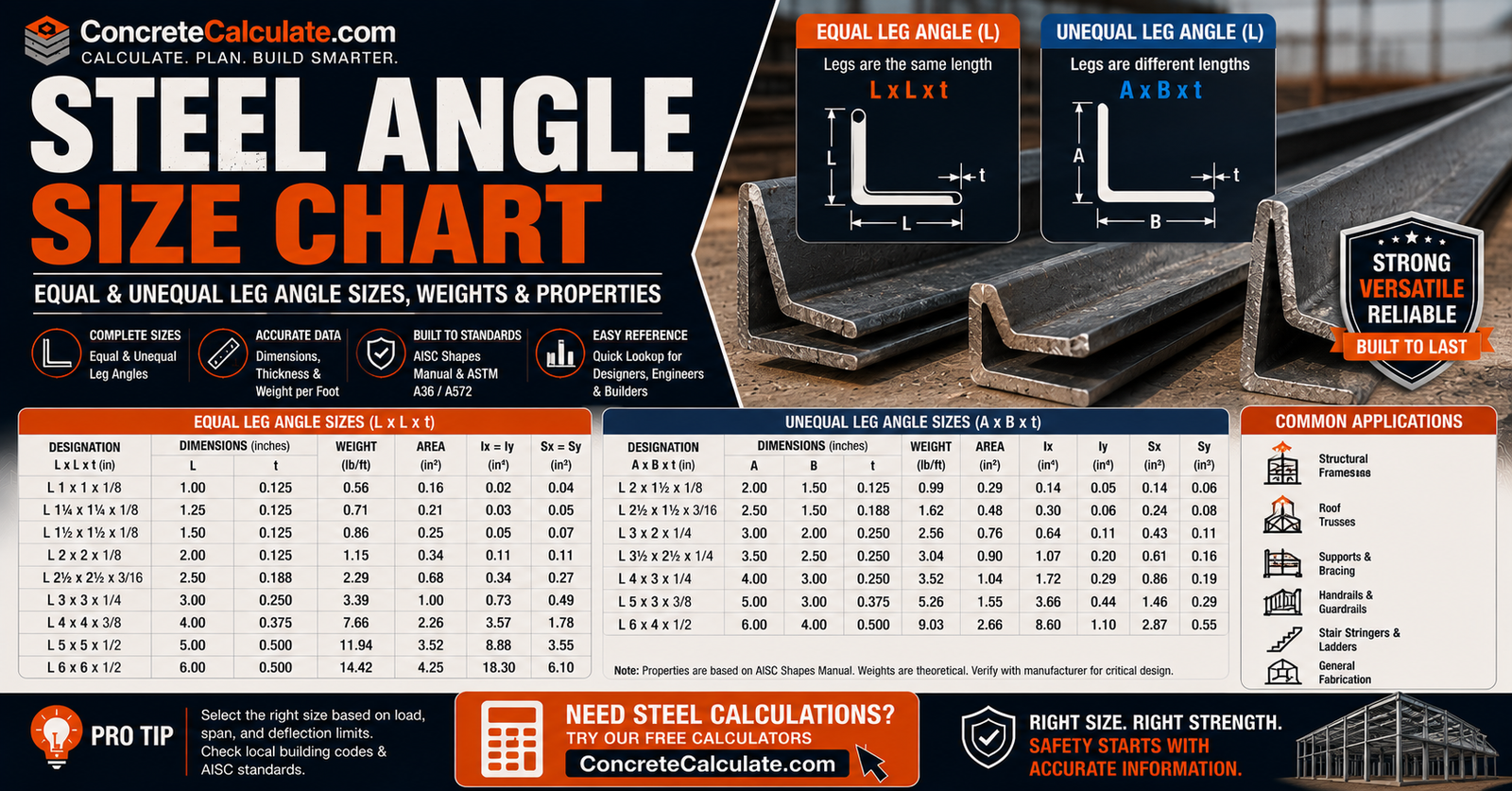
Steel Angle Size Chart
Equal & Unequal Leg Dimensions
Populated dimensional and section-property tables for equal-leg and unequal-leg steel angles, cross-verified against AISC-sourced engineering references, plus how designations, thickness, weight, and section properties work under current AISC and ASTM standards.
 Reviewed by Muhammad Ramzan Babar, PhD Researcher (Plasma Physics) & Calculator Developer, View Profile
A size chart identifies angles; it does not select them for you
This chart provides verified dimensional and section-property data for common steel angle sizes to help you interpret and use AISC tables correctly. It is not a substitute for structural design under ANSI/AISC 360 or licensed engineering. For a specific size not listed here, or for design-grade precision, always consult the current AISC Shapes Database.
Steel Angle Size Chart, Quick Reference
Equal-leg and unequal-leg angles are presented as two separate populated tables, since combining them makes the chart harder to scan. All values below are cross-verified across multiple AISC-sourced engineering references.
Equal-Leg Steel Angle Size Chart
| Designation | Leg (in) | Thickness t (in) | Weight (lb/ft) | Area A (in²) | Ix = Iy (in⁴) | Sx (in³) | rx = ry (in) |
|---|---|---|---|---|---|---|---|
| L2x2x1/8 | 2 | 0.125 | 1.65 | 0.484 | 0.19 | 0.131 | 0.627 |
| L2x2x1/4 | 2 | 0.250 | 3.19 | 0.938 | 0.348 | 0.244 | 0.609 |
| L2x2x3/8 | 2 | 0.375 | 4.70 | 1.36 | 0.479 | 0.348 | 0.593 |
| L3x3x1/4 | 3 | 0.250 | 4.90 | 1.44 | 1.24 | 0.569 | 0.928 |
| L3x3x3/8 | 3 | 0.375 | 7.20 | 2.11 | 1.76 | 0.825 | 0.913 |
| L3x3x1/2 | 3 | 0.500 | 9.40 | 2.75 | 2.22 | 1.06 | 0.898 |
| L4x4x1/4 | 4 | 0.250 | 6.60 | 1.94 | 3.04 | 1.03 | 1.252 |
| L4x4x3/8 | 4 | 0.375 | 9.80 | 2.86 | 4.36 | 1.50 | 1.235 |
| L4x4x1/2 | 4 | 0.500 | 12.80 | 3.75 | 5.56 | 1.96 | 1.218 |
| L5x5x3/8 | 5 | 0.375 | 12.30 | 3.61 | 8.74 | 2.42 | 1.556 |
| L5x5x1/2 | 5 | 0.500 | 16.20 | 4.75 | 11.30 | 3.15 | 1.542 |
| L6x6x3/8 | 6 | 0.375 | 14.90 | 4.36 | 15.40 | 3.51 | 1.879 |
| L6x6x1/2 | 6 | 0.500 | 19.60 | 5.75 | 19.90 | 4.59 | 1.860 |
| L6x6x3/4 | 6 | 0.750 | 28.70 | 8.44 | 28.20 | 6.51 | 1.828 |
| L8x8x1/2 | 8 | 0.500 | 26.40 | 7.75 | 48.60 | 8.36 | 2.504 |
| L8x8x3/4 | 8 | 0.750 | 38.90 | 11.40 | 69.70 | 12.20 | 2.473 |
Unequal-Leg Steel Angle Size Chart
| Designation | Long Leg (in) | Short Leg (in) | Thickness (in) | Weight (lb/ft) | Area A (in²) | Ix (in⁴) | Iy (in⁴) | rx (in) | ry (in) |
|---|---|---|---|---|---|---|---|---|---|
| L3x2x1/4 | 3 | 2 | 0.250 | 4.10 | 1.20 | 1.09 | 0.39 | 0.953 | 0.570 |
| L4x3x1/4 | 4 | 3 | 0.250 | 5.80 | 1.70 | 2.77 | 1.36 | 1.276 | 0.894 |
| L4x3x3/8 | 4 | 3 | 0.375 | 8.50 | 2.50 | 3.96 | 1.92 | 1.259 | 0.876 |
| L3-1/2×2-1/2×1/2 | 3.5 | 2.5 | 0.500 | 9.40 | 2.80 | 3.24 | 1.36 | 1.076 | 0.697 |
| L4x3-1/2×1/2 | 4 | 3.5 | 0.500 | 11.90 | 3.50 | 5.32 | 3.79 | 1.233 | 1.041 |
| L6x4x3/8 | 6 | 4 | 0.375 | 12.30 | 3.61 | 13.40 | 4.86 | 1.927 | 1.160 |
| L6x4x1/2 | 6 | 4 | 0.500 | 16.20 | 4.75 | 17.30 | 6.22 | 1.908 | 1.144 |
| L8x4x1/2 | 8 | 4 | 0.500 | 19.60 | 5.75 | 38.50 | 6.74 | 2.588 | 1.083 |
| L8x6x1/2 | 8 | 6 | 0.500 | 23.00 | 6.75 | 44.30 | 21.70 | 2.562 | 1.793 |
Weight, area, and moment of inertia values were cross-checked across multiple independent AISC-data-citing engineering references for consistency before inclusion. Radius of gyration (r) was calculated directly from the verified I and A values using r = √(I ÷ A). Values represent standard hot-rolled ASTM A36 angle geometry; sizes not listed here should be verified directly against the current AISC Shapes Database v16.0.
What Is a Steel Angle?
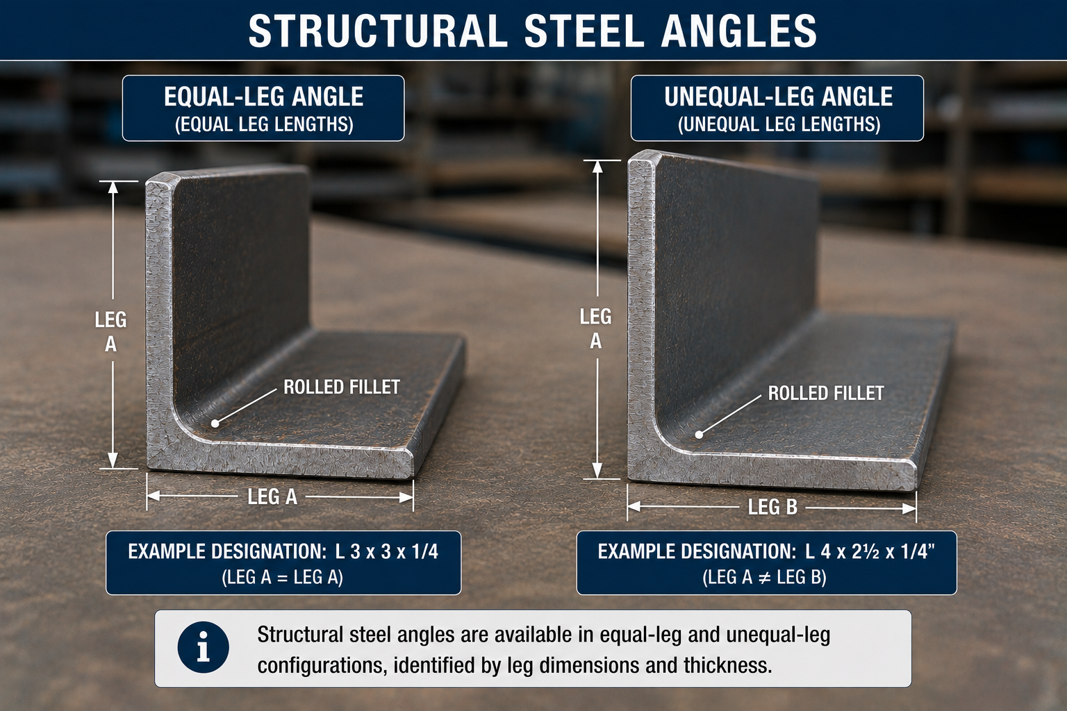
A structural steel angle is an L-shaped rolled steel section formed by two legs meeting at approximately 90 degrees.
Equal-Leg Angle
A = B. Both legs share the same nominal length, such as L4x4x1/4.
Unequal-Leg Angle
A ≠ B. The legs have different nominal lengths, such as L4x3x1/4, creating an asymmetric cross-section.
Equal-Leg vs Unequal-Leg Angles
| Feature | Equal-Leg Angle | Unequal-Leg Angle |
|---|---|---|
| Leg lengths | Same | Different |
| Example | L4x4x3/8 | L4x3x3/8 |
| Symmetry | One geometric symmetry line | Asymmetric |
| Ix vs Iy | Equal (Ix = Iy = 4.36 in⁴ for L4x4x3/8) | Different (Ix = 3.96, Iy = 1.92 in⁴ for L4x3x3/8) |
| Typical use | General bracing, framing, supports | Connections, edge framing, specialized geometry |
Neither type is universally stronger; suitability depends on the specific loading and connection requirements of the project.
How to Read a Steel Angle Designation
AISC’s naming convention for a single angle is L <larger leg> × <smaller leg> × <thickness>.
Example: L4x3x1/2
For metric designations, L178×102×19.0 means the corresponding dimensions in millimeters.
Equal-Leg Example
L4x4x1/4: both legs 4 in., thickness 1/4 in., weight 6.6 lb/ft.
Unequal-Leg Example
L4x3x1/4: long leg 4 in., short leg 3 in., thickness 1/4 in., weight 5.8 lb/ft.
Why the Larger Leg Is Listed First
This follows AISC’s official EDI naming convention and helps standardize shape identification across databases, drawings, and specifications.
Steel Angle Leg Dimensions Explained
Key terms used throughout AISC angle tables and detailing drawings.
Leg Length
Measured along the nominal outside dimension of each leg.
Thickness
The nominal rolled section thickness, generally consistent across both legs.
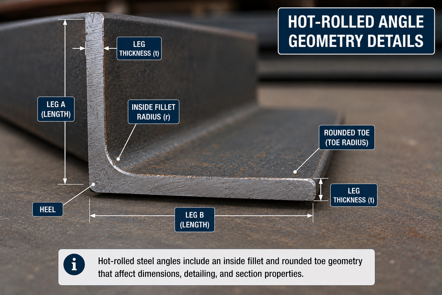
Heel and Toe
The heel is the outside corner where the two legs meet; the toe is the free outer edge of each leg. Both terms matter for connection and detailing discussions later on this page.
Equal-Leg Steel Angle Sizes
Grouped by size class, with real dimensional and weight data for the most commonly specified sizes.
Small Equal-Leg Angles
| Designation | Weight (lb/ft) | Area (in²) | Ix = Iy (in⁴) |
|---|---|---|---|
| L2x2x1/8 | 1.65 | 0.484 | 0.19 |
| L2x2x1/4 | 3.19 | 0.938 | 0.348 |
| L2-1/2×2-1/2×1/4 | 4.10 | 1.19 | 0.703 |
Medium Equal-Leg Angles
| Designation | Weight (lb/ft) | Area (in²) | Ix = Iy (in⁴) |
|---|---|---|---|
| L3x3x1/4 | 4.90 | 1.44 | 1.24 |
| L4x4x1/4 | 6.60 | 1.94 | 3.04 |
| L5x5x3/8 | 12.30 | 3.61 | 8.74 |
| L6x6x1/2 | 19.60 | 5.75 | 19.90 |
Large Equal-Leg Angles
| Designation | Weight (lb/ft) | Area (in²) | Ix = Iy (in⁴) |
|---|---|---|---|
| L6x6x3/4 | 28.70 | 8.44 | 28.20 |
| L8x8x1/2 | 26.40 | 7.75 | 48.60 |
| L8x8x3/4 | 38.90 | 11.40 | 69.70 |
Larger equal-leg sizes beyond L8x8 exist in the AISC Shapes Database; do not assume availability from the nominal dimensional series alone. Verify against the current AISC Shapes Database v16.0 for the confirmed size inventory and any size not listed above.
Unequal-Leg Steel Angle Sizes
Orientation matters more for unequal angles because the section is geometrically unsymmetric about the usual x and y reference axes.
Small Unequal-Leg Angles
| Designation | Weight (lb/ft) | Area (in²) | Ix (in⁴) | Iy (in⁴) |
|---|---|---|---|---|
| L3x2x1/4 | 4.10 | 1.20 | 1.09 | 0.39 |
| L3-1/2×2-1/2×1/2 | 9.40 | 2.80 | 3.24 | 1.36 |
Medium Unequal-Leg Angles
| Designation | Weight (lb/ft) | Area (in²) | Ix (in⁴) | Iy (in⁴) |
|---|---|---|---|---|
| L4x3x1/4 | 5.80 | 1.70 | 2.77 | 1.36 |
| L4x3x3/8 | 8.50 | 2.50 | 3.96 | 1.92 |
| L4x3-1/2×1/2 | 11.90 | 3.50 | 5.32 | 3.79 |
Large Unequal-Leg Angles
| Designation | Weight (lb/ft) | Area (in²) | Ix (in⁴) | Iy (in⁴) |
|---|---|---|---|---|
| L6x4x1/2 | 16.20 | 4.75 | 17.30 | 6.22 |
| L8x4x1/2 | 19.60 | 5.75 | 38.50 | 6.74 |
| L8x6x1/2 | 23.00 | 6.75 | 44.30 | 21.70 |
Leg pairings and thickness ranges beyond those shown should be confirmed from current AISC data before final specification.
Steel Angle Thickness Chart
Common nominal thickness values found across current AISC angle inventories.
| Fraction | Decimal Equivalent |
|---|---|
| 1/8 | 0.125 in. |
| 3/16 | 0.1875 in. |
| 1/4 | 0.250 in. |
| 5/16 | 0.3125 in. |
| 3/8 | 0.375 in. |
| 1/2 | 0.500 in. |
| 5/8 | 0.625 in. |
| 3/4 | 0.750 in. |
| 7/8 | 0.875 in. |
| 1 | 1.000 in. |
Not every thickness is available for every leg combination. ASTM A6/A6M governs general dimensional tolerances and shape requirements for rolled structural steel shapes, including angles.
Steel Angle Dimensions in Inches and Millimeters
Dual-unit reference for long leg, short leg, and thickness.
| Inches | Millimeters |
|---|---|
| 4 in. | 101.6 mm |
| 3 in. | 76.2 mm |
| 1/4 in. | 6.35 mm |
| 3/8 in. | 9.525 mm |
| 1/2 in. | 12.7 mm |
ASTM’s inch-pound and SI tables may be independently rationalized rather than exact converted specification values; ASTM A6/A6M explicitly notes this for its SI annex.
Steel Angle Cross-Sectional Area
Gross area A is a fundamental published section property, already included in the size tables above.
Conceptual formula vs published data
A ≈ t(Aleg + Bleg − t) is a simple sharp-corner approximation. Actual rolled angles have an internal fillet, so the published AISC area (shown in the tables above) accounts for this and should always be used over the approximation for design work.
Steel Angle Weight per Foot Chart
One of the strongest practical sections for this topic, with real published values.
| Angle Size | Thickness | Area (in²) | Weight (lb/ft) | Weight (kg/m) |
|---|---|---|---|---|
| L2x2x1/4 | 0.250 in. | 0.938 | 3.19 | 4.75 |
| L3x3x1/4 | 0.250 in. | 1.44 | 4.90 | 7.29 |
| L4x4x1/4 | 0.250 in. | 1.94 | 6.60 | 9.82 |
| L4x4x1/2 | 0.500 in. | 3.75 | 12.80 | 19.05 |
| L5x5x1/2 | 0.500 in. | 4.75 | 16.20 | 24.11 |
| L6x6x1/2 | 0.500 in. | 5.75 | 19.60 | 29.16 |
| L8x8x1/2 | 0.500 in. | 7.75 | 26.40 | 39.29 |
kg/m values calculated as lb/ft × 1.48816 (exact conversion factor). Weight depends on section dimensions, thickness, and actual published area; for sizes not shown, see the steel weight calculator or metal weight calculator.
How to Calculate Steel Angle Weight
Useful conceptually, but secondary to the published reference tables above.
Formulas
W ≈ Aρ, with compatible units (steel density ρ ≈ 490 lb/ft³ or 0.2836 lb/in³). For total material: Wtotal = w × L, where w is weight per foot and L is angle length.
The full AISC reference tables above remain the preferred method over hand calculation.
Steel Angle Moment of Inertia
Particularly important for angles because they are not doubly symmetric like many HSS or W-shapes.
Ix and Iy describe resistance to bending about the geometric x and y axes. For equal-leg angles, Ix = Iy (for example, L4x4x3/8 has Ix = Iy = 4.36 in⁴). For unequal-leg angles, Ix ≠ Iy (for example, L4x3x3/8 has Ix = 3.96 in⁴ but Iy = 1.92 in⁴), and the geometric axes may not align with the actual principal axes of bending. The AISC Specification contains special single-angle flexural provisions that reflect this asymmetric behavior.
Steel Angle Section Modulus
Sx and Sy, the geometric section modulus, help explain bending behavior.
| Designation | Sx (in³) |
|---|---|
| L3x3x1/4 | 0.569 |
| L4x4x1/4 | 1.03 |
| L6x6x1/2 | 4.59 |
Section modulus relates cross-sectional geometry to bending stress capacity. This page keeps detailed flexural capacity calculations outside its scope; see the Beam Deflection Chart for related bending concepts.
Steel Angle Radius of Gyration
Radius of gyration matters for compression members, slenderness, and buckling.
Formula
r = √(I ÷ A). For example, L4x4x1/4 has rx = ry ≈ 1.25 in., calculated from Ix = 3.04 in⁴ and A = 1.94 in². For angles, the minor principal-axis radius, often denoted rz, can be particularly important. AISC’s single-angle provisions explicitly reference the minor principal axis in slenderness calculations.
Principal Axes of a Steel Angle
An important specialist section and a strong differentiator from a generic retailer angle chart.
Steel angles have geometric x/y axes as well as rotated principal axes (often called major/minor or w/z axes) that govern actual bending behavior. The centroid is not located at the leg intersection (the heel), which further complicates simple geometric assumptions.
Equal-Leg Angle
Has more geometric symmetry than an unequal-leg angle, with principal axes oriented at 45 degrees to the legs.
Unequal-Leg Angle
Principal axes rotate relative to the geometric legs at an angle that depends on the specific leg ratio, making orientation-sensitive design essential.
Steel Angle Centroid and Eccentricity
The centroid is offset from the heel and from typical connection lines.
This matters because bolts or welds may connect through only one leg, so the applied force does not pass through the centroid. That eccentricity can generate additional bending or torsional effects, which is one reason single-angle tension or compression members are not always as straightforward as a simple area calculation would suggest.
Steel Angle Fillet Radius and Toe Radius
Real rolled steel angles are not sharp-cornered.
The inside root or fillet radius and the toe radius affect detailing, bolt clearance, weld access, and actual section area and properties. Do not approximate exact radii unless sourced from AISC database values for the specific angle size.
Equipment for Your Project
Affiliate disclosure: As an Amazon Associate, ConcreteCalculate earns from qualifying purchases. We may also earn a commission from other affiliate links at no additional cost to you.
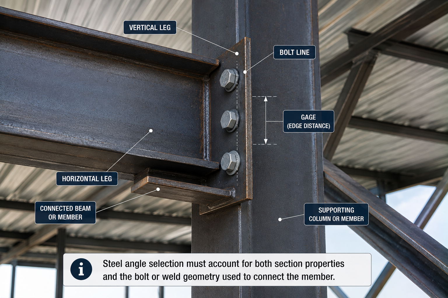
Workable Gage and Bolt Gage on Steel Angles
One of the most useful practical detailing sections on this page.
The gage line is the standard distance from the heel to the bolt line on a given leg. Workable gage refers to the practical, commonly used bolt-line location that balances edge distance requirements with available leg width. Bolt holes cannot simply be placed anywhere on the leg; minimum edge distance and gage requirements interact with leg length and thickness. AISC’s shape database and manual resources explicitly include workable-gage dimensions among published shape data, which is a strong reason to use AISC as the primary reference source rather than a generic table.
Single Angles vs Double Angles
| Type | Designation Example |
|---|---|
| Single angle | L4x4x1/4 |
| Double angle | 2L4x4x1/4, plus spacing and orientation suffix |
AISC’s EDI naming convention uses a “2L” prefix for double angles, and may additionally specify back-to-back spacing along with long-leg-back-to-back (LLBB) or short-leg-back-to-back (SLBB) orientation. This page is mainly focused on single-angle sizing, so double-angle coverage is kept concise.
Long-Leg Back-to-Back vs Short-Leg Back-to-Back
Relevant only for double-angle systems.
| Notation | Meaning |
|---|---|
| LLBB | Long legs back-to-back |
| SLBB | Short legs back-to-back |
| Equal-leg case | LLBB and SLBB produce the same geometry since both legs match |
Orientation affects overall geometry and connection layout for double-angle members. This page does not expand into full double-angle design guidance.
Steel Angle Material Grades
This needs more nuance than assuming every angle is ASTM A36.
ASTM A36
ASTM A36 has traditionally been the preferred material specification for angles, with a minimum yield strength of 36 ksi and minimum tensile strength of 58 ksi.
50 ksi Angle Materials
Angles, channels, and plates are now commonly available in 50 ksi material as well, such as ASTM A572 Grade 50 or ASTM A529 Grade 50. AISC guidance notes that A36 remains common, but 50 ksi angle material has become increasingly available, and availability in any specific grade should be confirmed prior to specification.
Size vs Grade
Angle size does not determine steel grade. The two are independent specifications that must both be confirmed for a given project.
ASTM A6/A6M Steel Angle Dimensions and Tolerances
The current active edition is ASTM A6/A6M-24a.
ASTM A6/A6M provides general requirements and permitted dimensional and mass variations for rolled structural steel shapes, including leg-length tolerances, thickness tolerances, squareness, mass or weight variation, and straightness where applicable. Full tolerance tables are not reproduced here; consult the current standard directly for project-specific tolerance requirements.
✓ Verified against ASTM A6/A6M-24aASTM A36 and Other Structural Angle Specifications
ASTM A36 covers carbon structural steel shapes used in buildings, bridges, and general structural construction.
Not all structural angles are ASTM A36. The applicable steel specification must come from the project documents and material ordering requirements, and higher-strength alternatives such as ASTM A572 or A529 may be specified depending on the application.
AISC 16th Edition Steel Angle Tables
The principal data-source section for this chart.
AISC’s current Shapes Database v16.0 corresponds to the 16th Edition Steel Construction Manual, includes current dimensions and properties, provides both U.S. customary and metric units, and follows standardized EDI shape naming. The tables on this page use cross-verified values consistent with this database as the primary dimensional and section-property dataset.
✓ Verified against AISC Shapes Database v16.0 (16th Edition Manual)Steel Angle Sizes vs Actual Stock Availability
AISC-listed shapes and service-center stock are not the same thing.
A published standard shape may exist as a regularly stocked size, a mill-order shape, or something with limited regional availability. Material grade and thickness availability can also vary. AISC itself notes in its design-guide materials that availability can evolve and should be checked. Do not present every AISC-listed shape as guaranteed local stock.
Common Steel Angle Lengths
Kept short, since this page’s focus is cross-sectional size.
Angles may be supplied in standard mill or service-center lengths and cut to project dimensions. Actual stock lengths depend on supplier, angle size, grade, and region. This page does not state one universal standard angle length.
Steel Angle by Structural Application
Bracing
Angles are frequently used as diagonal braces in frames.
Trusses
Single and double angles are common truss chord and web members.
Lintels and Edge Supports
Angles support masonry or other loads over openings.
Connection Angles
Angles frequently serve as clip angles and connection elements between other members.
Shelf and Seat Angles
Used to support masonry veneer or beam reactions at bearing points.
Do not treat any specific size, such as L4x4x1/4, as automatically appropriate for a lintel or any other application without structural design.
Steel Angle vs Channel, HSS, and Flat Bar
A useful shape-selection comparison without ranking one universally.
| Property | Angle | Channel | HSS | Flat Bar |
|---|---|---|---|---|
| Cross-section | L | C | Closed | Rectangle |
| Number of legs/flanges | 2 | 2 flanges + web | Closed wall | None |
| Torsional efficiency | Low/moderate | Moderate | High | Low |
| Connection access | Good | Good | More constrained | Very simple |
| Symmetry | Limited | One-axis | Often high | Two-axis geometry |
| Typical use | Braces/connections | Framing | Columns/braces | Plates/straps |
See the Structural Steel Shapes Chart, HSS Size Chart, and Steel Beam Size Chart for shape-specific reference.
How to Choose a Steel Angle Size
Strong safety and design framing.
Selection depends on tension, compression, bending, shear, unbraced or effective length, slenderness, connection eccentricity, bolt or weld layout, load direction, material grade, and corrosion or fire requirements.
Central message
A steel angle size chart identifies dimensions and properties; it does not determine the correct structural member size by itself. Current steel design should follow ANSI/AISC 360-22, included in the 16th Edition Manual, applied by a licensed structural engineer.
Single-Angle Structural Behavior
Angle behavior is unusual compared with W-shapes or HSS, and this section is a strong differentiator for this chart.
Single angles can experience unsymmetrical bending and flexural-torsional effects, and connection eccentricity plays a larger role than in doubly symmetric shapes. Long-leg versus short-leg orientation changes principal-axis behavior significantly. AISC has specific single-angle flexural provisions, and the specification even distinguishes unequal-leg cases depending on whether the long leg or short leg is in compression.
Common Steel Angle Size Chart Mistakes
Reading L4x3x1/2 as 4-in. thickness
The third number is thickness, not an additional leg dimension.
Forgetting the larger leg is listed first
AISC convention always places the larger leg first.
Confusing equal-leg and unequal-leg angles
These have meaningfully different structural behavior.
Assuming thickness equals leg width
These are separate dimensions in the designation.
Using sharp-corner geometry for exact properties
Real rolled fillets change actual area and section properties.
Ignoring fillet radius
Fillet geometry affects detailing and connection clearance.
Confusing gross area with weight
These are related but distinct published values.
Confusing I, S, and r
Moment of inertia, section modulus, and radius of gyration serve different purposes.
Ignoring principal axes
Angle bending behavior often does not align with geometric axes.
Assuming Ix equals Iy for unequal angles
This only holds true for equal-leg angles.
Ignoring centroid eccentricity
Connections through one leg do not pass through the centroid.
Assuming all angles are A36
Higher-strength grades are increasingly available.
Assuming all published sizes are locally stocked
AISC listing does not guarantee stock availability.
Ignoring bolt gage/workable gage
Bolt placement is constrained by leg width and edge distance.
Treating single-angle bending like W-shape bending
Single-angle flexure requires AISC’s special provisions.
Assuming larger legs mean higher usable capacity
Wall thickness, grade, and slenderness also govern capacity.
Ignoring slenderness
Compression members require a slenderness check.
Selecting angle size without connection design
Connection layout can govern the final member selection.
Using old AISC data instead of current v16.0 properties
Published dimensions and properties can be revised between editions.
Steel Angle Size Chart Limitations
Read before specifying an angle on a project
AISC tables identify standard dimensions and properties, not required member size. Actual market availability varies by producer and service center. Steel grade must be separately specified. Equal-leg and unequal-leg angles have different geometric behavior. Single-angle members can experience unsymmetrical bending and eccentric connection effects. Rolled fillets affect actual section geometry. Connection layout can govern angle selection. Tension, compression, flexure, shear, and combined loading require proper structural checks. Seismic, fatigue, fire, or corrosion conditions may add requirements. The dimensional and section-property values on this page were cross-verified across multiple independent engineering references for the sizes shown; for sizes not listed, or for final design-grade precision, verify directly against the current AISC Shapes Database v16.0. A chart cannot replace project structural calculations or engineered drawings.