Subfloor Screw Spacing Chart – Edge, Field and Joist Fastening
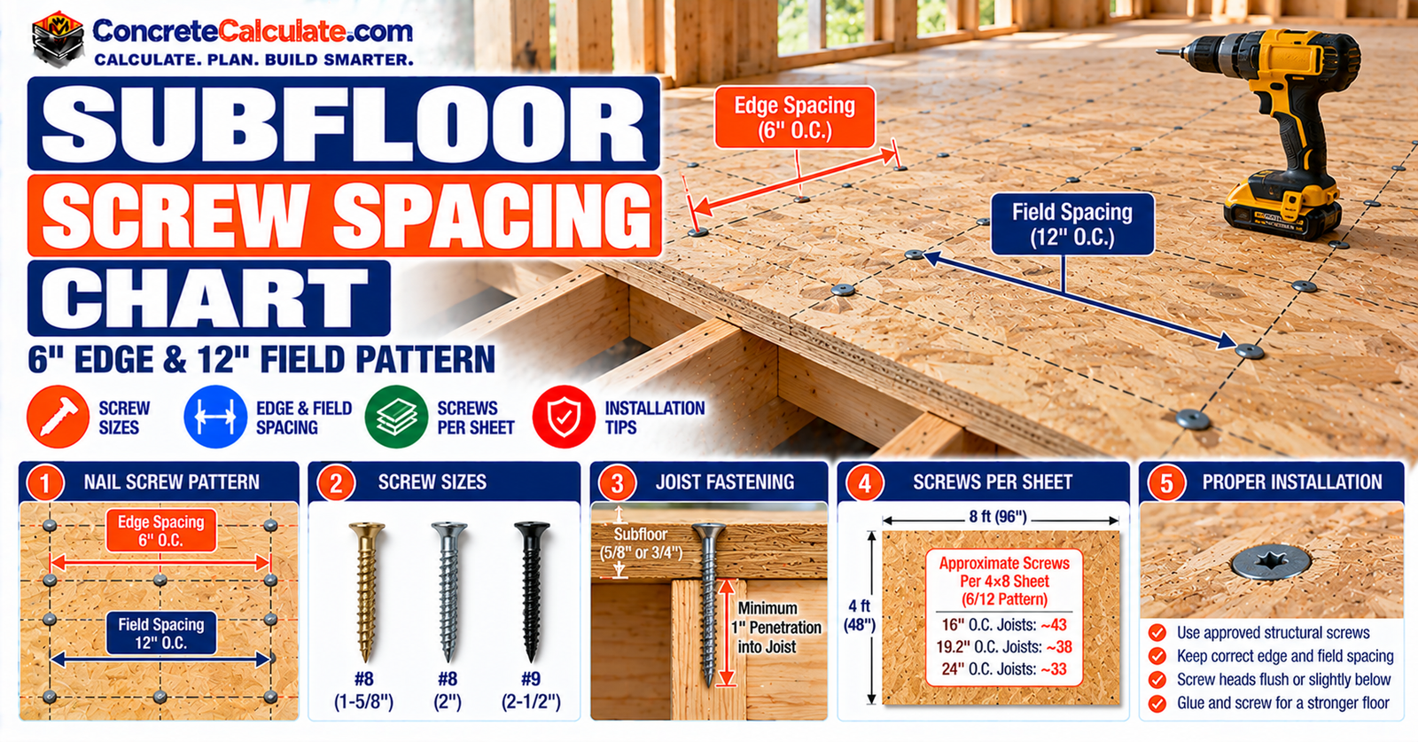
Subfloor Screw Spacing ChartEdge, Field and Joist Fastening
A practical reference for carpenters, builders and inspectors: the 6-inch edge and 12-inch field screw pattern, screw sizes and penetration, screws per sheet, adhesive timing and installation checks, kept separate from the IRC nail schedule.
Jump to the Chart Reviewed by Muhammad Ramzan Babar, PhD Researcher (Plasma Physics) & Calculator Developer, View Profile
Key Facts
- Common pattern: screws 6 in. on center along supported panel ends and 12 in. on center along intermediate joists (6/12), with screws approved for structural subfloor use.
- The IRC subfloor schedule lists nails at 6/12. It does not automatically approve every screw.
- Huber recommends #8 screws up to 23/32 in. panels and #9 above, with at least 1 in. of penetration. A 4×8 panel over 16 in. joists has about 43 theoretical screw positions.
Subfloor Screw Spacing Chart: Quick Reference
The 6/12 screw pattern with the conditions that make it valid.
Most structural subfloors are screwed 6 inches on center at supported panel edges and 12 inches on center at intermediate joists. That 6/12 pattern comes from manufacturer guidance for approved screws. It is not an IRC screw schedule, because the IRC lists nails. For joist sizes and spans see the Floor Joist Size Chart.
How to Read This Chart
A 23/32 in. structural OSB subfloor over wood joists at 16 in. on center, with a manufacturer-approved screw: screws along the supported 4 ft panel ends at 6 in. maximum, screws along intermediate joists at 12 in. maximum, and no screw line along unsupported tongue-and-groove edges. The 6/12 pattern describes spacing only. It does not set screw diameter, length or floor strength.
| Fastening location or condition | Maximum spacing | Metric equivalent | Technical qualification |
|---|---|---|---|
| Supported panel ends | 6 in. o.c. | 152.4 mm | Screws into the framing under the 4 ft ends |
| Supported panel edges | 6 in. o.c. | 152.4 mm | Only where framing or blocking supports the edge |
| Intermediate joists | 12 in. o.c. | 304.8 mm | Typical unblocked diaphragm recommendation |
| Supported floor perimeter | 6 in. o.c. | 152.4 mm | Subject to the approved fastening detail |
| Unsupported tongue-and-groove side joint | Not a screw line | n/a | No joist beneath; do not drive unsupported screws |
| Blocked structural diaphragm | Per approved design | Varies | Simpson suggests about 15% more screws |
| Engineered or proprietary subfloor system | Manufacturer or design schedule | Varies | The exact approval governs |
- 6/12 is supported by manufacturer guidance. It does not mean the IRC approves every subfloor screw at these spacings.
- Use screws approved for structural subfloor use, and follow the code, approved plans, panel instructions and the fastener evaluation report.
- The schedule is for wood structural subfloor panels on compatible framing, not every underlayment or floor system.
- Every screw must land in framing or approved blocking. Check panel thickness, joist spacing, screw length, penetration and adhesive compatibility separately.
- Maximum spacing means closer spacing is allowed where approved. Arbitrary closer spacing does not add capacity.
Sources: Simpson Strong-Tie Quik Drive fastener guide (6 in. at boundaries, 12 in. in the field, unblocked diaphragm; about 15% more screws for blocked diaphragms) and the Huber AdvanTech Subflooring Installation Manual (6 in. maximum on supported edges, 12 in. maximum at intermediate supports).
What Is Subfloor Screw Spacing?
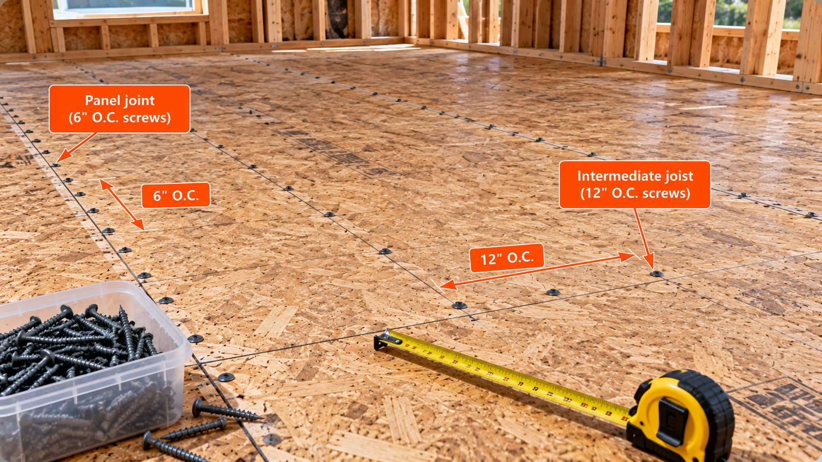
Center-to-Center Spacing
Spacing is measured from the center of one screw to the center of the next along a joist line or panel edge.
Structural Subfloor Fastening
Screws attach structural wood panels to the floor joists, so the panels act with the framing. They carry vertical loads into the joists and, in a diaphragm, help resist lateral forces.
Why Screw Placement Matters
A screw that misses the joist, sits too near the panel edge or is overdriven holds little. Even spacing only works if each screw lands in framing and is seated correctly.
Subfloor Screw Spacing Code Requirements
Three different things get blended together: the IRC’s nail schedule, manufacturer screw guidance and APA’s floor recommendations.
2024 IRC Table R602.3(1)
| Panel thickness | Nail listed in the IRC | Supported edges | Intermediate supports |
|---|---|---|---|
| 3/8 in. to 1/2 in. | 6d common, or deformed nail (2 × 0.113 in. × 0.266 in. head), or 2-3/8 × 0.113 in. × 0.266 in. head nail | 6 in. | 12 in. |
| 19/32 in. to 3/4 in. | 8d common (2-1/2 × 0.131 in.), or deformed nail (2-3/8 × 0.113 in. × 0.266 in. head) | 6 in. | 12 in. |
| 7/8 in. to 1-1/4 in. | 10d common (3 × 0.148 in.), or 8d deformed (2-1/2 × 0.131 in. × 0.281 in. head) | 6 in. | 12 in. |
Source: 2024 International Residential Code, Table R602.3(1). Do not read this table with the word screws in place of the listed nails.
Simpson Strong-Tie Guidance
Simpson’s fastener guide says to space screws 6 in. at the boundaries and 12 in. in the field for an unblocked diaphragm, and to use about 15% more screws for blocked diaphragms. Its Strong-Drive WSV subfloor screw is evaluated under ICC-ES AC233 and AC120.
APA Floor Construction Recommendations
APA recommends nails 6 in. on panel ends and edges and 12 in. at intermediate supports, 3/8 in. from panel edges, with a 1/8 in. gap at end joints and edges including tongue-and-groove.
Manufacturer Approval
Screws Need Their Own Approval
A screw is acceptable only if the code, an evaluation report or the panel maker approves it for the application. Follow the approved plans and the locally adopted code.
Subfloor Edge Screw Spacing
Supported Panel Ends
Panels run with their 8 ft length across the joists, so the 4 ft ends land on a joist. Screws along those ends are 6 in. on center at most. The end joint should fall on the joist’s center line with at least 1/2 in. of bearing.
Supported Side Edges
Side edges are tongue-and-groove and usually fall between joists. They are not a screw line unless approved blocking sits beneath them.
Floor Perimeters
Panels at the floor perimeter bear on the rim or band joist, and the approved detail sets the spacing there.
Proper Screw Setback
APA says to fasten panels 3/8 in. from panel edges, and Huber’s manual gives a 3/8 in. to 1/2 in. maximum edge distance.
Subfloor Field Screw Spacing
Intermediate Joists
Screws along the joists under the interior of the panel are 12 in. on center at most in the 6/12 pattern.
12-Inch Spacing
The 12 in. maximum is also what the IRC nail schedule and APA use for intermediate supports, so the pattern is consistent across sources even though the fasteners differ.
Locating Framing
Snap chalk lines on the joist centers before fastening so every screw lands in wood.
Unsupported Panel Edges
Do not drive screws along unsupported edges between joists. If an edge is unsupported, add blocking where required.
6/12 Subfloor Screw Pattern
Meaning of 6/12
6/12 means 6 in. on center at supported edges and 12 in. on center at intermediate supports.
Typical Applications
It is the common pattern for new structural subfloors on wood joists, supported by Simpson’s and Huber’s guidance and by the IRC and APA nail schedules.
Installation Layout
Mark joist lines, then fasten the supported ends first at 6 in., then the intermediate lines at 12 in.
Limitations
It assumes an approved screw, approved panel and framing, and an unblocked diaphragm.
Screw Count for a 4×8 Panel at 6/12
Variables: Ne = screws per end line; Ni = screws per intermediate line; m = joist lines under the panel (7 at 16 in. o.c.)
Practical interpretation: This is an idealized count. Edge setbacks, cut panels and floor perimeters change it.
Closer Subfloor Screw Spacing
6/8 and 6/6 Patterns
Some projects specify closer screws, such as 6 in. at edges and 8 in. or 6 in. at intermediate supports. These are project-specific, not universal code requirements. An earlier Huber installation guide, for example, called for 6 in. at edges and intermediate locations for 1-1/8 in. panels over joists spaced more than 24 in. on center.
Engineered Diaphragms
Blocked diaphragms and engineered shear floors can need more screws; Simpson suggests about 15% more for blocked diaphragms.
Manufacturer-Specified Fastening
Follow the panel maker’s schedule. Extra screws without an approved reason do not raise capacity and can damage panels.
Subfloor Screw Size Chart
#8 Screws
Huber recommends #8 screws for AdvanTech panels up to and including 23/32 in. thick.
#9 Screws
For panels over 23/32 in., Huber recommends #9 screws.
| Panel thickness | Huber screw recommendation | Minimum framing penetration |
|---|---|---|
| 19/32 in. | #8 | 1 in. |
| 23/32 in. | #8 | 1 in. |
| 7/8 in. | #9 | 1 in. |
| 1 in. | #9 | 1 in. |
| 1-1/8 in. | #9 | 1 in. |
Source: Huber Engineered Woods, AdvanTech Subflooring Installation Manual. These are Huber product recommendations, not universal screw sizes for every plywood, OSB or engineered subfloor.
Screw Diameter
Gauge alone does not identify a screw. Simpson’s Strong-Drive WSV subfloor screw is a #9 with a 6-lobe head and variable thread, and Simpson recommends its 2 in. length for AdvanTech. General dimensions are in the Screw Size Chart and the Wood Screw Size Chart.
Thread and Head Design
Thread type, head design, length, coating, evaluation and framing compatibility all matter. Use a screw approved for structural subfloor use.
Subfloor Screw Length Chart
Panel Thickness
Thicker panels leave less screw in the framing. A 1-1/8 in. panel with a 2-1/2 in. screw leaves 1.375 in.
Minimum Penetration
Huber requires at least 1 in. of penetration into the framing for AdvanTech. Other evaluated products may specify different conditions.
| Panel thickness | Illustrative screw length | Theoretical penetration |
|---|---|---|
| 19/32 in. | 2 in. | 1.406 in. |
| 23/32 in. | 2 in. | 1.281 in. |
| 23/32 in. | 2-1/2 in. | 1.781 in. |
| 7/8 in. | 2-1/2 in. | 1.625 in. |
| 1-1/8 in. | 2-1/2 in. | 1.375 in. |
Screw Penetration
Variables: P = penetration into framing; Ls = screw length; Tp = panel thickness
Practical interpretation: This exceeds Huber’s 1 in. minimum in the simple example, but screw approval and other installation conditions still control.
Approved Fastener Selection
The lengths above are geometric examples. They are not a list of approved products. A particular screw may call for a longer length or minimum thread engagement.
Subfloor Screw Spacing for Plywood
Structural Plywood
Structural plywood subfloor is fastened to joists with the same 6/12 pattern as other wood structural panels. Panel thicknesses are in the Plywood Thickness Chart.
Supported Panel Edges
Plywood ends bear on joists; tongue-and-groove edges between joists are not screw lines.
Framing Attachment
Use screws approved for structural subfloor. Plywood underlayment over an existing subfloor has its own fastening rules, so do not use underlayment schedules for structural plywood.
Manufacturer Instructions
Follow the panel maker’s instructions and the fastener evaluation.
Subfloor Screw Spacing for OSB
OSB Subfloor Panels
OSB subfloor panels use the same 6/12 pattern. OSB does not automatically need a different schedule from plywood. Panel categories are in the OSB Thickness Chart.
Performance Category
The panel’s Performance Category and span rating must suit the joist spacing. The screw pattern does not replace that check.
Tongue-and-Groove Joints
Engage the tongue and groove fully and keep the end gaps. Screws are not driven along the T&G edge.
Screw Installation
Seat heads slightly below the surface but do not crush the OSB surface.
Subfloor Screw Spacing for 3/4-Inch and 23/32-Inch Panels
Actual Panel Thickness
A 3/4 in. Performance Category panel is 23/32 in. thick. Check the grade stamp.
#8 Screw Example
For panels up to 23/32 in., Huber recommends a #8 screw with at least 1 in. of penetration. A 2 in. screw through a 23/32 in. panel gives about 1.28 in.
Framing Penetration
Verify penetration for the screw you choose and the framing member.
Panel Span Rating
Choose the panel from the span rating and joist spacing first.
Subfloor Screw Spacing for Thicker Panels
7/8-Inch Panels
Huber recommends #9 screws for panels over 23/32 in.
1-Inch Panels
The same #9 recommendation applies, with at least 1 in. of penetration.
1-1/8-Inch Panels
A 2-1/2 in. screw through a 1-1/8 in. panel gives 1.375 in. of penetration.
#9 Screw Example
Do not generalize Huber’s recommendations to every manufacturer or panel.
Subfloor Screw Spacing for 16-, 19.2-, and 24-Inch Joists
Wider joist spacing means fewer joist lines and fewer screws, but the screw spacing itself does not change.
| Joist spacing | Joist lines under an 8 ft panel | Edge spacing | Intermediate spacing | Theoretical screws per panel |
|---|---|---|---|---|
| 16 in. o.c. | 7 | 6 in. | 12 in. | 43 |
| 19.2 in. o.c. | 6 | 6 in. | 12 in. | 38 |
| 24 in. o.c. | 5 | 6 in. | 12 in. | 33 |
16-Inch Joist Layout
Seven joist lines cross an 8 ft panel: 96 ÷ 16 + 1.
19.2-Inch Joist Layout
Six lines: 96 ÷ 19.2 + 1.
24-Inch Joist Layout
Five lines. The panel must be rated for 24 in. spans, and 24 in. spacing does not allow wider screw spacing.
Panel Span Compatibility
The panel’s span rating must permit the joist spacing. Joist spans are in the Floor Joist Span Chart.
Subfloor Screws vs. Nails
Structural Screw Performance
A dedicated subfloor screw has been tested for holding and diaphragm performance, which is what an evaluation report documents.
| Feature | Approved subfloor screws | Code-listed subfloor nails |
|---|---|---|
| Common fastening pattern | 6/12 in qualifying systems | 6/12 in selected IRC entries |
| Withdrawal resistance | Product-specific | Nail-type-specific |
| Size | Evaluation or manufacturer | IRC schedule |
| Installation tool | Screw gun or collated driver | Hammer or nailer |
| Adhesive compatibility | Check system instructions | Check system instructions |
| Structural diaphragm performance | Requires an approved application | Based on code or design |
| Substitution | Not automatically interchangeable | Not automatically interchangeable |
Common and Ring-Shank Nails
The IRC lists common and deformed nails. APA recommends ring- or screw-shank nails for floor panels, 6d for panels up to 3/4 Performance Category and 8d for thicker ones. Nail dimensions are in the Framing Nail Size Chart and the Nail Size Chart.
Withdrawal Resistance
It depends on the exact screw or nail. Do not assume all screws hold better than all nails.
Approved Substitutions
Huber allows any code-approved subfloor fastener, including nails, screws and hybrid fasteners, for AdvanTech panels. That shows substitution depends on the approval.
Subfloor Adhesive and Screw Spacing
APA Glued Floor System
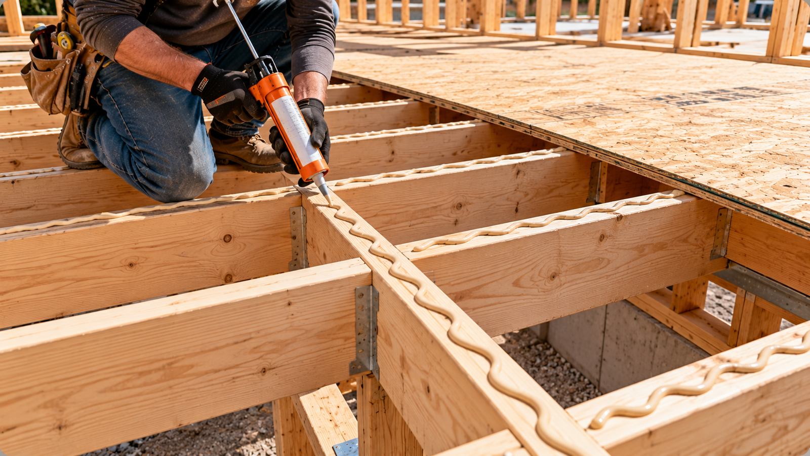
APA recommends gluing and fastening for a stiffer, quieter floor. Glue-nailing is recommended for APA floor panels, and the same idea applies to screws.
Compatible Adhesives
Use adhesive meeting APA AFG-01 or ASTM D3498, applied as the adhesive manufacturer directs. Huber specifies compatible polyurethane or solvent-based adhesives for AdvanTech.
Adhesive Open Time
Install all supported-edge and intermediate fasteners before the adhesive skins over or cures, and do not fasten corners first and finish later. Warm weather speeds setting.
Why Screws Remain Necessary
Adhesive does not replace required fasteners unless an approved assembly says so.
Subfloor Screw Edge Distance and Panel Gaps
3/8-Inch Edge Setback
Keep screws about 3/8 in. from panel ends and edges.
1/8-Inch Panel Gap
APA recommends about 1/8 in. at all end joints and edges, including tongue-and-groove, unless the panel manufacturer says otherwise. Use a spacer tool.
| Measurement | Recommendation | Purpose |
|---|---|---|
| Panel gap at end joints and edges | About 1/8 in. (APA), including tongue-and-groove | Allows moisture-related expansion |
| Screw setback from panel edge | About 3/8 in. (APA); 3/8 in. to 1/2 in. maximum (Huber) | Prevents edge damage and gives proper fastening |
| Supported end bearing | At least 1/2 in. on the joist (APA) | Supports the panel end |
Tongue-and-Groove Joint Spacing
Huber’s AdvanTech panels have spacing built into the tongue and groove, and short-end joints are spaced by hand.
Avoiding Edge Damage
Screws too close to the edge split or crumble the panel. The gap and the setback do different jobs.
How to Install Subfloor Screws Correctly
Prepare Joists
- Prepare and clean the joists, and check that the framing is level and aligned.
Apply Adhesive and Position Panels
- Apply adhesive to the joist tops.
- Position the panel with its strength axis across the joists, ends on joist centers.
Mark Screw Lines and Drive Screws
- Snap or mark the screw lines over the joists.
- Drive screws at the schedule spacing, starting at one corner and working to the remaining edges, before the adhesive skins.
Inspect Installation
- Inspect the installation for spacing, seating and missed joists.
Sequencing matters: finish all fastening while the adhesive is workable. Seat heads slightly below the panel surface without stripping the hole.
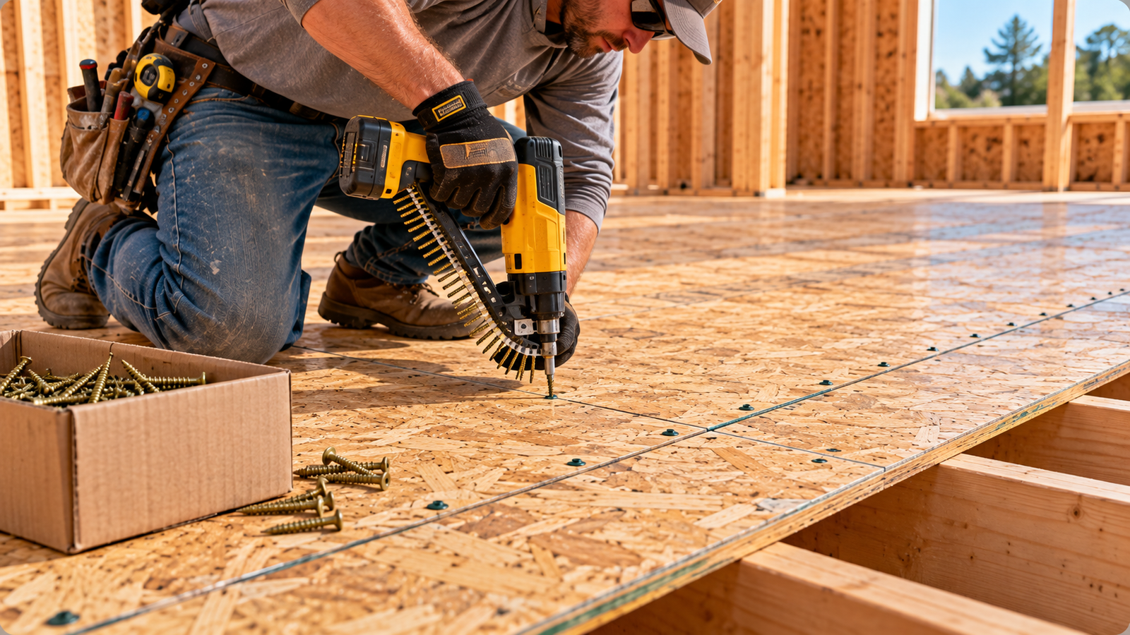
How Many Screws per 4×8 Subfloor Sheet?
Worked Screw Count
Screws Along One Fastening Line
Variables: L = line length; s = maximum spacing; N = theoretical screw positions
Practical interpretation: Before corner setbacks.
16-Inch Joists
43 theoretical screws, as the 6/12 example showed.
19.2-Inch Joists
38 theoretical screws.
24-Inch Joists
33 theoretical screws.
| Joist spacing | Joist lines | Screws per panel | Rounded |
|---|---|---|---|
| 16 in. o.c. | 7 | 43 | About 43 |
| 19.2 in. o.c. | 6 | 38 | About 38 |
| 24 in. o.c. | 5 | 33 | About 33 |
These are layout counts. Actual edge setbacks, cut panels, floor perimeters and framing alignment change the final number.
Subfloor Screw Quantity Calculator
Floor Area
Measure the floor area in square feet.
Panel Quantity
Subfloor Panel Quantity
Variables: Af = floor area (ft²); 32 ft² = nominal coverage of a 4×8 panel
Practical interpretation: Before cuts, waste and layout constraints.
Screw Count
Preliminary Screw Purchase Quantity
Variables: Ns = screws to buy; Npanel = screws per panel; w = estimating allowance
Practical interpretation: Planning estimate only, not an exact takeoff or an approved fastening schedule.
| Joist spacing | Screws per panel | Estimated screws |
|---|---|---|
| 16 in. o.c. | 43 | 1,183 |
| 19.2 in. o.c. | 38 | 1,045 |
| 24 in. o.c. | 33 | 908 |
Waste Allowance
The 10% allowance is an assumption. Adjust it for the layout, cuts and extra screws for repairs.
Subfloor Screw Spacing for Repairs and Squeaky Floors
Finding Joists
Locate joists from the original nail or screw lines, a stud finder, or from below if the joists are accessible. A screw that misses the joist cannot stop a squeak.
Adding Approved Screws
Add approved subfloor screws into the joists along the squeaky area. Pilot-hole sizes are in the Pilot Hole Size Chart.
Loose Subfloor Panels
A loose panel may need to be re-secured along its supported edges and intermediate joists.
When Screws Cannot Solve the Problem
Screws do not fix excessive joist span, damaged tongue-and-groove edges, wet or deteriorated sheathing or too much deflection. Keep repairs separate from a structural retrofit design.
Subfloor Fastening for Engineered Joists and Trusses
I-Joist Flanges
I-joist flanges are narrower than lumber joists, so screws need correct placement and approved size. Follow the I-joist maker’s fastener limits. Spans are in the TJI Floor Joist Span Chart.
Floor Truss Chords
Truss chords have their own fastening instructions.
Screw Penetration
Penetration is limited by the flange or chord thickness, so check the maximum screw length.
Manufacturer Requirements
Proprietary assemblies need compatible fasteners and placement from the joist maker.
Subfloor Screw Spacing Under Tile, Hardwood and Vinyl
Structural Subfloor vs. Underlayment
The structural subfloor carries the loads. Underlayment is a nonstructural layer over it, and its screw schedule is different.
Tile Substrate Requirements
Tile needs a stiff, flat substrate and may use cement backer board with its own screw spacing from the board maker and tile standards (TCNA).
Hardwood Flooring
Hardwood follows the flooring maker’s and NWFA’s substrate and fastening requirements.
Resilient Flooring
Vinyl and other resilient products need a smooth underlayment per the flooring manufacturer.
Do not replace those requirements with one generic screw schedule.
Common Subfloor Screwing Mistakes and Inspection Checklist
Wrong Screw Type
Using drywall screws
They are not structural subfloor fasteners.
Using the nail table for screws
The IRC table lists nails.
Spacing screws too wide
Stay within 6 in. and 12 in. where the pattern applies.
Incorrect Spacing and Missed Joists
Missing the joists
Chalk the joist lines.
Overdriving screws
Crushed OSB or plywood loses holding.
Leaving screws proud
They telegraph through finishes.
Poor Adhesive Application, Panel Gaps and Moisture
Poor adhesive application
Fasten before the adhesive skins.
Ignoring panel gaps
Leave about 1/8 in.
Installing wet panels
Moisture swells and buckles the floor.
Screwing too close to edges
Keep about 3/8 in. back.
Inspection Checklist
| Inspection item | Verification |
|---|---|
| Panel | Approved plywood or OSB type and span rating |
| Joists | Spacing, alignment and structural adequacy |
| Screw | Approved model, gauge and length |
| Supported edges | Maximum permitted spacing |
| Intermediate supports | Maximum permitted spacing |
| Penetration | Meets product requirements |
| Panel gap | Manufacturer-required spacing |
| Edge distance | Proper setback |
| Adhesive | Compatible and applied within open time |
| Screw heads | Correct seating, no damaged panels |
| Joints | Proper T&G engagement and stagger |
| Finish flooring | Additional substrate requirements checked |
Subfloor Screw Spacing FAQs
Spacing and Patterns
How far apart should subfloor screws be?
The common pattern is 6 in. on center along supported panel ends and 12 in. on center at intermediate joists, with approved screws.
Is 6/12 the standard subfloor screw pattern?
It is the common manufacturer-supported pattern, matching the IRC and APA nail spacing. It is not an IRC screw schedule.
What does 6 inches at edges and 12 inches in the field mean?
Screws no more than 6 in. apart along supported panel edges and ends, and no more than 12 in. apart along the intermediate joists.
Does the IRC allow screws instead of nails?
Table R602.3(1) lists nails. Screws are accepted where they are approved for the application, for example through an evaluation report.
What size screws should I use for 3/4-inch subfloor?
For AdvanTech up to 23/32 in., Huber recommends #8 screws with 1 in. of penetration. Other panels follow their makers’ instructions.
Are 2-inch screws long enough for 23/32-inch OSB?
A 2 in. screw gives about 1.28 in. of theoretical penetration through 23/32 in. OSB, above Huber’s 1 in. minimum, if the screw is approved.
How many screws do I need for a 4×8 sheet?
About 43 theoretical screws over 16 in. joists, 38 over 19.2 in. and 33 over 24 in., at 6/12.
Is 6/6 screw spacing better?
Not automatically. Closer spacing is project-specific and does not add capacity unless it is approved.
Should subfloor screws be countersunk?
Seat the heads flush to slightly below the surface. Do not crush the panel or strip the hole.
Can drywall screws be used for subflooring?
No. Use screws approved for structural subfloor fastening.
Should subfloor panels be glued and screwed?
APA recommends gluing and fastening for a stiffer, quieter floor. Use compatible adhesive and finish all fastening before it skins over.
Do screws prevent floor squeaks?
Properly placed screws into the joists help, especially with adhesive, but they do not fix excessive span or deflection.
Do screws go into tongue-and-groove joints?
No. Those joints fall between joists and are not screw lines unless approved blocking is beneath them.
Does 24-inch joist spacing require more screws?
No, it needs fewer joist lines. The spacing along each line does not change, and the panel must be rated for the span.
Is subfloor screw spacing different for plywood and OSB?
No. The same 6/12 pattern applies, subject to the panel and screw instructions.
Can I screw a new subfloor over an old one?
Underlayment over an old subfloor uses a different fastening schedule. Check the panel and flooring manufacturer’s instructions.
Sources and Scope Limits
6/12 Alone Is Not Enough
The screws must be approved for the structural application, properly sized, driven into compatible framing with adequate penetration and installed according to the governing floor-system requirements. Screws do not correct excessive joist span, undersized panels, damaged edges or wet sheathing. The IRC nail schedule, the manufacturer screw guidance and the approved plans are separate sources, and verify the selected fastener’s current evaluation report and the locally adopted code.
Primary References
- Simpson Strong-Tie, Quik Drive Fastener Guide for Major Applications
- Simpson Strong-Tie, Strong-Drive WSV Subfloor Screw
- Huber Engineered Woods, AdvanTech Subflooring Installation Manual
- 2024 International Residential Code, Table R602.3(1) (ICC)
- APA, Engineered Wood Construction Guide, Floors
- APA, Underlayment and Subfloor
- APA, Construct a Solid, Squeak-Free Floor System
Download Subfloor Screw Spacing Chart PDF
Use your browser’s print function to save this page as a PDF for jobsite binders and inspection files. The printed version hides interactive elements and keeps the tables.