Framing Nailing Schedule Chart – Studs, Plates, Joists and Rafters
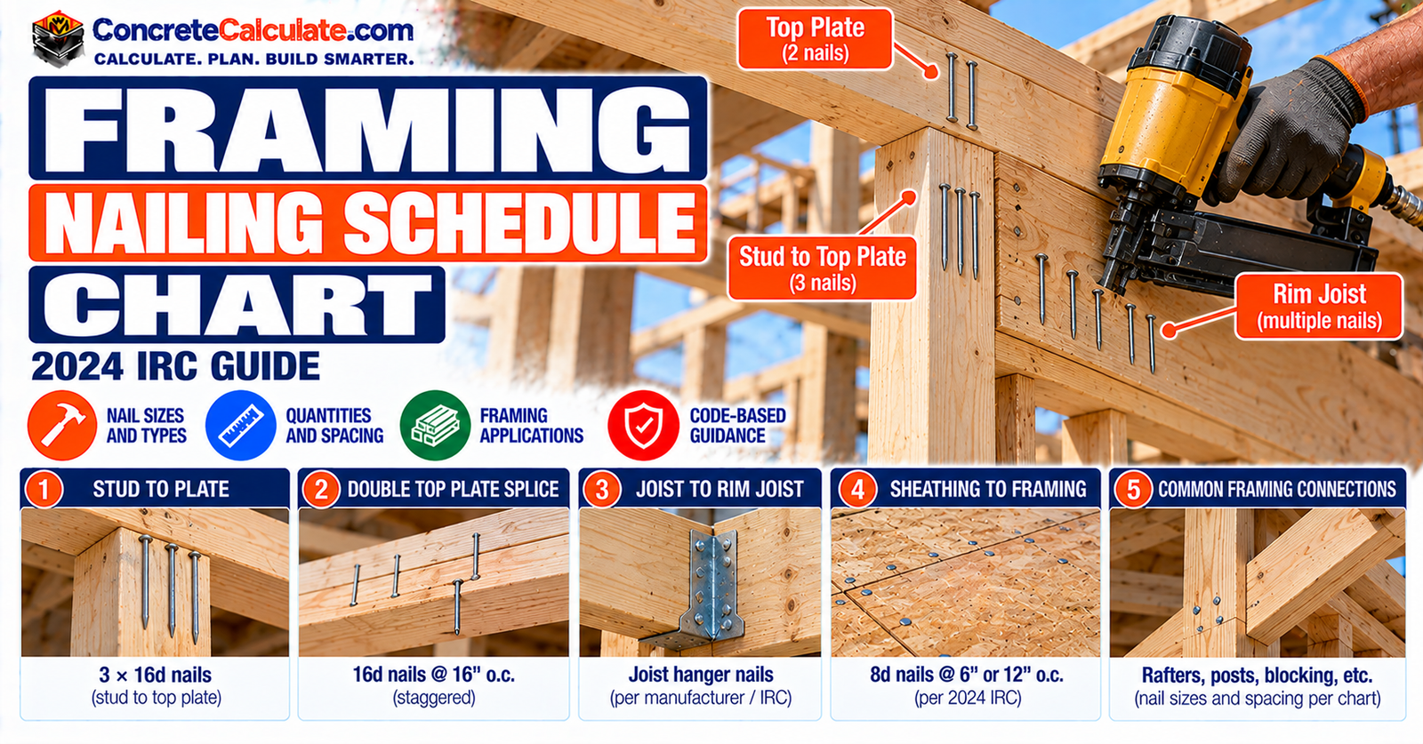
Framing Nailing Schedule ChartStuds, Plates, Joists and Rafters
Connection-specific nail sizes, quantities, methods and maximum spacing for residential wood framing. Selected reference options, not a substitute for the complete adopted code and approved plans.
 By Muhammad Ramzan Babar, PhD Researcher in Plasma Physics & Construction Calculator Developer
Framing Nailing Schedule Chart: Quick Reference
Which nail, how many, which method and what spacing for common residential framing connections.
A nailing schedule answers four questions for each connection: which nail, how many, what method and how far apart. That is different from a nail size chart, which only lists nail dimensions (see the Framing Nail Size Chart for those). This chart shows selected connections from the 2024 International Residential Code.
How to Read This Chart
Pick the connection, then read its nail, method and spacing together from the same row. Example: a stud end-nailed to a plate uses 2-16d common nails, each 3-1/2 in. long with a 0.162 in. shank, driven through the plate into the end of the stud. Nail count per connection is not the same thing as spacing along a member. A connection with a count (2 per connection) has no on-center spacing, and one with spacing (16 in. o.c.) is repeated along the member.
| Framing connection | Selected code-listed nail option | Nailing method | Spacing or quantity | IRC item |
|---|---|---|---|---|
| Stud to top or bottom plate | 2-16d common (3-1/2 × 0.162 in.) | End nail | 2 per connection | 17 |
| Stud to top or bottom plate | 4-8d common (2-1/2 × 0.131 in.) | Toe nail | 4 per connection | 17 |
| Stud to stud, not at braced wall panels | 16d common | Face nail | 24 in. o.c. | 8 |
| Stud to stud and abutting studs at intersecting wall corners, at braced wall panels | 16d common | Face nail | 16 in. o.c. | 9 |
| Top plate to top plate | 16d common | Face nail | 16 in. o.c. | 13 |
| Double top plate splice | 8-16d common | Face nail | Each side of end joint; 24 in. min. lap each side | 14 |
| Bottom plate to joist, rim joist, band joist or blocking (not at braced wall panels) | 16d common | Face nail | 16 in. o.c. | 15 |
| Bottom plate to joist, rim joist, band joist or blocking (at braced wall panels) | 2-16d common | Face nail | 16 in. o.c. | 16 |
| Built-up header (2 in. to 2 in. with 1/2 in. spacer) | 16d common | Face nail | 16 in. o.c. along each edge | 10 |
| Continuous header to stud | 4-8d common | Toe nail | 4 per connection | 11 |
| Ceiling joist to top plate | 3-8d common | Toe nail | 3 per joist | 2 |
| Rafter or roof truss to plate | 3-10d common (3 × 0.148 in.) | Toe nail | 2 toe nails on one side and 1 on the opposite side | 6 |
| Joist to sill, top plate or girder | 3-8d common | Toe nail | 3 per connection | 22 |
| Rim joist, band joist or blocking to sill or top plate | 8d common | Toe nail | 6 in. o.c. | 23 |
| Band or rim joist to joist | 3-16d common | End nail | 3 per connection | 27 |
- Each row is one alternative. Never mix the nail count of one alternative with the nail size of another.
- 16d common does not mean any nail sold as 16d. Box, sinker and gun nails with the same label are different sizes.
- On-center spacing is a maximum. Double top plate splices need the prescribed lap and nail placement.
- Braced wall panels, roof uplift connections, seismic and wind provisions and structural connectors can add requirements beyond this table.
- Use the full code table and the locally adopted edition for construction and inspection.
Source: 2024 International Residential Code, Table R602.3(1), Fastening Schedule. The item numbers refer to the table rows.
What Is a Framing Nailing Schedule?
Definition
A framing nailing schedule is a table that sets the fasteners for each framing connection. In the IRC it is the fastening schedule in Table R602.3(1).
Nails per Connection vs. Spacing
Some rows give a number of nails for one connection, such as 3-8d common nails to toe-nail a joist. Others give an on-center spacing, such as 16d common nails at 16 in. along a top plate. Do not turn a count into a spacing or the reverse.
The nails carry loads from one framing member to the next. A connection with too few, too small or misplaced nails weakens the whole load path.
2024 IRC Framing Nailing Code Requirements
R602.3
Section R602.3 requires components of exterior wood-frame walls to be fastened in accordance with Tables R602.3(1) through R602.3(4). Table R602.3(1) is the fastening schedule, with separate sections for roof, wall, floor and wood structural panel connections. The table’s footnote also sets minimum bending yield strengths for the nails, so nails must be carbon steel with the stated yield strengths unless designed otherwise.
Local Codes
The 2024 IRC is a model code. Each jurisdiction adopts a particular edition and may amend it. Engineered connections, high-wind and seismic regions and proprietary framing systems can need different fastening.
Local Code and Plans Control
Use the locally adopted code edition and the approved plans. The chart on this page is a selected reference, not a replacement for the full table and its footnotes.
Framing Nailing Methods
Each row of the schedule names a method. End, toe and face nailing give different holding, so you cannot swap one for another.
| Method | Nail direction | Typical applications |
|---|---|---|
| End nailing | Through one member into the end grain of another | Stud to plate, rim joist to joist |
| Toe nailing | At an angle through one member into another | Joist to sill, rafter to plate |
| Face nailing | Through the broad face of one member into another | Built-up studs, plates, headers |
| Blind nailing | Fastener hidden by the adjoining piece | Selected plank and subfloor connections (blind and face nail) |
End Nailing and Toe Nailing
End nailing drives nails through a plate into the end of a stud. Toe nailing slants nails through the side of the stud into the plate, so it needs more nails (4-8d common instead of 2-16d common). No universal toe-nailing angle applies.
Face Nailing and Blind Nailing
Face nailing is used for built-up studs, plates and headers. Blind nailing appears with face nailing for 2 in. subfloor, where the code calls for 3-16d box or 2-16d common nails.
Stud-to-Plate Nailing Schedule
This is one of the most common connections in a house, and the code lists several complete alternatives.
| Method | Code-listed alternatives |
|---|---|
| End nail | 3-16d box (3-1/2 × 0.135 in.); or 2-16d common (3-1/2 × 0.162 in.); or 3-10d box (3 × 0.128 in.); or 3-3 in. × 0.131 in. nails |
| Toe nail | 4-8d box (2-1/2 × 0.113 in.); or 3-16d box; or 4-8d common (2-1/2 × 0.131 in.); or 4-10d box; or 4-3 in. × 0.131 in. nails |
Source: 2024 International Residential Code, Table R602.3(1), Fastening Schedule.
End-Nailing Requirements
Two 16d common nails, or three of the lighter 16d box, 10d box or 3 in. × 0.131 in. nails, go through the plate into the end of the stud.
Toe-Nailing Requirements
Four 8d common nails, or the other listed alternatives. Studs installed after the wall is raised are often toe-nailed.
8d vs. 16d Alternatives
8d toe nails and 16d end nails are different complete alternatives, not interchangeable counts.
Installation Examples
For a wall assembled flat, end-nail through the plate. For a stud placed in the field, toe-nail. The schedule is separate from stud layout; see the Stud Spacing Chart for spacing.
Stud-to-Stud Nailing Schedule
Built-Up Studs
Built-up studs are face-nailed together with the spacing in the row below.
| Connection | Code-listed alternatives | Method | IRC item |
|---|---|---|---|
| Stud to stud, not at braced wall panels | 16d common (3-1/2 × 0.162 in.) at 24 in. o.c.; or 10d box (3 × 0.128 in.) or 3 in. × 0.131 in. nails at 16 in. o.c. | Face nail | 8 |
| Stud to stud and abutting studs at intersecting wall corners (at braced wall panels) | 16d common at 16 in. o.c.; or 16d box (3-1/2 × 0.135 in.) or 3 in. × 0.131 in. nails at 12 in. o.c. | Face nail | 9 |
Source: 2024 International Residential Code, Table R602.3(1), Fastening Schedule.
Ordinary Wall Sections
Ordinary walls use 16d common nails at 24 in. on center, or lighter nails at a closer 16 in. spacing.
Braced Wall Panels
At braced wall panels, the spacing tightens to 16 in. for 16d common nails and to 12 in. for the lighter alternatives. Bracing methods have their own rules.
Corner Stud Connections
Abutting studs at intersecting wall corners in braced wall panels follow the same row. Stud size and height limits are in Table R602.3(5); the Stud Spacing Chart covers layout.
Double Top Plate Nailing Schedule
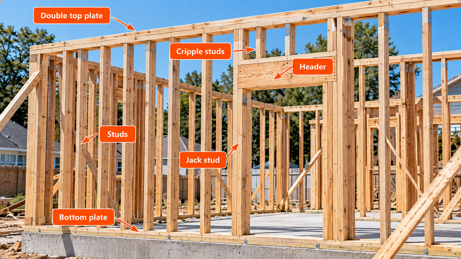
Wood stud walls get a double top plate, with end joints offset at least 24 in. Joints in plates do not need to land on studs. Plates are at least 2 in. nominal thick and as wide as the studs.
| Connection | Code-listed alternatives | Method | IRC item |
|---|---|---|---|
| Top plate to top plate | 16d common at 16 in. o.c.; or 10d box (3 × 0.128 in.) or 3 in. × 0.131 in. nails at 12 in. o.c. | Face nail | 13 |
| Top plates, laps at corners and intersections | 3-10d box; or 2-16d common; or 3-3 in. × 0.131 in. nails | Face nail | 18 |
Source: 2024 International Residential Code, Table R602.3(1), Fastening Schedule. and Section R602.3.2.
Plate-to-Plate Fastening
The plates are face-nailed together along their length.
16-Inch Spacing
16d common nails at 16 in. on center is the first alternative.
Alternative Nail Sizes
The lighter 10d box or 3 in. × 0.131 in. nails are listed at 12 in. on center instead.
Proper Placement
At corners and intersections where plates lap, use the separate corner row above.
Double Top Plate Splice Nailing
Item 14 of the schedule is a distinct connection detail, not a continuation of the regular 16 in. spacing.
Lap Length and Nail Quantity
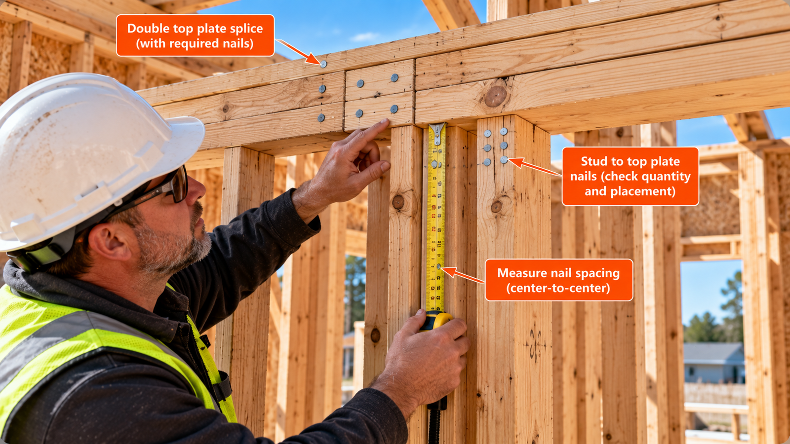
The code calls for 8-16d common nails (or 12-16d box, 12-10d box or 12-3 in. × 0.131 in. nails), face-nailed on each side of the end joint, with a minimum 24 in. lap splice length each side.
Top Plate Splice Nail Count
Variables: N = nails on each side of the end joint
Practical interpretation: Placed according to the full code detail. This is additional to ordinary plate fastening where applicable.
Corner and Intersection Laps
Where plates lap at corners and intersections, use the separate row (3-10d box, or 2-16d common, or 3-3 in. × 0.131 in. nails).
Common Errors
Putting end joints in both plates on the same stud, laps shorter than 24 in., and fewer nails than the item calls for.
Bottom Plate Nailing Schedule
Plate to Floor Framing
The bottom plate is face-nailed to joists, rim joists, band joists or blocking.
| Connection | Code-listed alternatives | Method | IRC item |
|---|---|---|---|
| Bottom plate to joist, rim joist, band joist or blocking, not at braced wall panels | 16d common at 16 in. o.c.; or 16d box (3-1/2 × 0.135 in.) or 3 in. × 0.131 in. nails at 12 in. o.c. | Face nail | 15 |
| Bottom plate to joist, rim joist, band joist or blocking, at braced wall panels | 3-16d box; or 2-16d common; or 4-3 in. × 0.131 in. nails, at 16 in. o.c. | Face nail | 16 |
Source: 2024 International Residential Code, Table R602.3(1), Fastening Schedule.
Ordinary Walls
One 16d common nail at 16 in. along the plate.
Braced Wall Panels
Two 16d common nails (or equivalent alternatives) every 16 in., a heavier connection.
Foundation Anchorage Distinction
Nails Do Not Replace Anchor Bolts
These nails connect a plate to wood floor framing. A sole plate on a concrete foundation is held down by anchor bolts or approved anchors. See the Anchor Bolt Spacing Chart.
Header and Opening Framing Nailing
Built-Up Headers
The built-up header row assumes two 2 in. members with a 1/2 in. spacer. Header sizes are in the Header Size Chart.
| Connection | Code-listed alternatives | Method | IRC item |
|---|---|---|---|
| Built-up header (2 in. to 2 in. with 1/2 in. spacer) | 16d common at 16 in. o.c. along each edge; or 16d box at 12 in. o.c. along each edge | Face nail | 10 |
| Continuous header to stud | 5-8d box; or 4-8d common; or 4-10d box (3 × 0.128 in.) | Toe nail | 11 |
| Adjacent full-height stud to end of header | 4-16d box; or 3-16d common; or 4-10d box; or 4-3 in. × 0.131 in. nails | End nail | 12 |
Source: 2024 International Residential Code, Table R602.3(1), Fastening Schedule.
Headers, Jack Studs, King Studs
The full-height stud next to each header end is end-nailed to the header (item 12). The count of jack studs and full-height studs comes from separate tables; see the Jack Stud Chart.
Engineered headers such as LVL follow the manufacturer’s fastening instructions, not this table.
Floor Joist Nailing Schedule
Joist-to-Sill and Joist-to-Girder Connections
Use item 22 when the joist bears on a sill, plate or girder. Hanger connections follow their manufacturer instead.
| Connection | Fasteners | Method | IRC item |
|---|---|---|---|
| Joist to sill, top plate or girder | 3-8d common; or 4-8d box; or 3-10d box; or 3 nails, 3 × 0.131 in. | Toe nail | 22 |
| Rim, band joist or blocking to sill/top plate | 8d common, 10d box or 3 × 0.131 in. nails at 6 in. o.c.; or 8d box at 4 in. o.c. | Toe nail | 23 |
| Band or rim joist to joist | 3-16d common; or 4-10d box; or 4 nails, 3 × 0.131 in. | End nail | 27 |
| Bridging or blocking to joist, rafter or truss | 2-8d common; or 2-10d box; or 2 nails, 3 × 0.131 in. | Toe nail at each end | 30 |
Rim Joist Connections
The rim-to-joist end nails and the rim-to-plate toe nails are separate connections. Install both where required.
Blocking and Bridging
Item 30 requires the listed pair at each end, not two nails total for both ends.
Built-Up Beam and Girder Nailing
Multiple Lumber Layers
| Location | Fastener option | Placement |
|---|---|---|
| Each 2-inch lumber layer | 20d common, 4 × 0.192 in. | 32 in. o.c. at top and bottom, staggered |
| Alternative layer fastening | 10d box, 3 × 0.128 in., or 3 × 0.131 in. nails | 24 in. o.c. at top and bottom, staggered on opposite sides |
| Ends and each splice, in addition to layer fastening | 2-20d common; or 3-10d box; or 3 nails, 3 × 0.131 in. | Face nail |
Staggered Fastening
Stagger the top and bottom rows. The alternative nail size changes the row spacing, so preserve each complete option.
Splices and Ends
The end/splice nails are additional to the repeated layer fastening. A nail schedule does not authorize a beam splice at any arbitrary location.
Engineered Beam Requirements
LVL, PSL, glulam and other engineered members require their own fastening and splice designs.
Equipment for Your Project
Affiliate disclosure: As an Amazon Associate, ConcreteCalculate earns from qualifying purchases. We may also earn a commission from other affiliate links at no additional cost to you.
Ceiling Joist Nailing Schedule
Ceiling Joist to Top Plate
Three 8d common nails are one permitted option per joist-to-plate connection.
| Connection | Fasteners | Method | IRC item |
|---|---|---|---|
| Ceiling joist to top plate | 3-8d common; or 4-8d box; or 3-10d box; or 3 nails, 3 × 0.131 in. | Toe nail, per joist | 2 |
| Ceiling joist not attached to parallel rafter, laps over partitions | 3-16d common; or 4-10d box; or 4 nails, 3 × 0.131 in. | Face nail; see R802.5.2 | 3 |
| Ceiling joist attached to parallel rafter, heel joint | Table R802.5.2(1) | Face nail | 4 |
| Collar tie to rafter | 3-10d common; or 4-10d box; or 4 nails, 3 × 0.131 in. | Face nail at each rafter | 5 |
| Rafter or roof truss to plate | 3-10d common; or 3-16d box; or 4-10d box; or 4 nails, 3 × 0.131 in. | Toe nail; specified arrangement and footnote i | 6 |
Joist Laps Over Partitions
The lap row applies to joists not attached to parallel rafters. Check R802.5.2 as well as the fastening schedule.
Ceiling Joist to Parallel Rafter
Heel-joint fastening comes from Table R802.5.2(1), not from the three-nail ceiling-joist-to-plate option.
Connection-Specific Requirements
Do not apply one ceiling connection count to every connection of the same member.
Roof Rafter Nailing Schedule
Rafter-to-Top-Plate
| Connection | Fastener option | Method/placement |
|---|---|---|
| Rafter or truss to plate | 3-10d common, 3 × 0.148 in. | Two toe nails on one side and one on opposite side |
| Rafters to ridge, valley or hip rafters, or to minimum 2-inch ridge beam | 3-10d common; or 4-16d box; or 4-10d box; or 4 nails, 3 × 0.131 in. | Toe nail |
| Same ridge/valley/hip connection, end-nail option | 2-16d common; or 3-16d box; or 3-10d box; or 3 nails, 3 × 0.131 in. | End nail |
Footnote i permits omitting the opposite-side rafter toe nail where a rafter is connected to an adjacent parallel ceiling joist according to the schedule, with the specified rafter and ceiling-joist-to-plate fastening.
Rafter-to-Ridge, Hip and Valley Connections
Item 7 lists separate toe-nail and end-nail options. Match the method to the connection geometry.
Wind Uplift Requirements
Ordinary Toe Nails Are Not a Complete Uplift Design
Check R802.11 for roof uplift and R602.3.5 for the braced wall uplift load path. R602.3.5 allows schedule-only fastening only under its specified conditions, including wind speed at most 115 mph, Exposure B, roof pitch at least 5:12, roof span at most 32 ft and net wall uplift at most 100 plf. Otherwise use the required connectors or designed load path.
Collar Tie and Rafter Tie Nailing
Collar Tie Connections
Item 5 permits three 10d common nails, or four 10d box nails, or four 3 × 0.131 in. nails, face-nailed at each rafter.
Rafter Tie Connections
Rafter ties resist outward roof thrust. Their connections are not interchangeable with collar-tie connections.
Ceiling Joist Heel Joints
For a ceiling joist attached to a parallel rafter, use Table R802.5.2(1). The required count depends on roof configuration and loading.
Code-Specified Nail Quantities
Do not assign the collar tie three-nail option to a heel joint or rafter tie without checking the governing roof provision.
Wall Sheathing Nailing Schedule
Supported Panel Edges and Intermediate Studs
| Application | Panel thickness | Specified nail | Edges | Intermediate | Scope |
|---|---|---|---|---|---|
| Exterior wall WSP | 7/16 in., span rating 24/16 | 8d common, 2-1/2 × 0.131 in.; 1-3/4 in. minimum penetration | 6 in. | 12 in. | R602.3(3), wind, exposure and specific-gravity conditions |
| Roof WSP | 3/8 to 1/2 in. and 19/32 to 3/4 in. | 8d common, 2-1/2 × 0.131 × 0.281 in. head; or RSRS-01, 2-3/8 × 0.113 × 0.281 in. head | 6 in. | 6 in. | R602.3(1), roof-specific rows and footnote f |
| Subfloor WSP | 19/32 to 3/4 in. | 8d common, 2-1/2 × 0.131 in.; or deformed 2-3/8 × 0.113 × 0.266 in. head | 6 in. | 12 in. | R602.3(1), supported-edge conditions |
| Braced wall sheathing | Per bracing method | Per approved bracing schedule | Per method | Per method | R602.10 or engineered design |
Braced Wall Sheathing
Wind-pressure resistance and wall bracing are separate checks. Use R602.10 for the chosen bracing method.
Wind Pressure Requirements
For the 7/16 in., 24/16-rated wall panel with 8d common nails, Table R602.3(3) allows 6/12 with 16 in. stud spacing up to 170 mph in Exposure B, 140 mph in C or 135 mph in D. With 24 in. studs the limits are 140, 115 and 110 mph respectively. Where framing specific gravity is 0.35 to less than 0.42, the maximum field spacing is 8 in., rather than 12 in. Other table conditions also apply.
Roof Sheathing Nailing Schedule
Roof Panel Thickness
The 2024 IRC roof rows for 3/8 through 3/4 in. panels use 8d common or RSRS-01 nails at 6/6. The 7/8 through 1-1/4 in. row uses 10d common or the specified deformed nail at 6/12.
Edge and Field Nailing
Nail supported panel edges, not unsupported edges between rafters. At spans of 48 in. or more, nails must be at most 6 in. at all supports.
High-Wind Conditions
Footnote f requires 4 in. at gable-end framing and intermediate supports within 48 in. of roof edges and ridges above 130 mph in Exposure B or 110 mph in C. Framing specific gravity conditions apply. See the Roof Sheathing Nail Spacing Chart for the complete layout discussion.
Subfloor Nailing Schedule
Wood Structural Subfloor Panels
| Panel thickness | Nail option | Edge / intermediate spacing (in.) |
|---|---|---|
| 3/8 to 1/2 in. | 6d common/deformed, 2 × 0.113 × 0.266 in. head, or 2-3/8 × 0.113 × 0.266 in. head nail | 6 / 12 |
| 19/32 to 3/4 in. | 8d common, 2-1/2 × 0.131 in., or deformed 2-3/8 × 0.113 × 0.266 in. head nail | 6 / 12 |
| 7/8 to 1-1/4 in. | 10d common, 3 × 0.148 in., or deformed 2-1/2 × 0.131 × 0.281 in. head nail | 6 / 12 |
Supported Edges and Intermediate Joists
Edge spacing applies to edges supported by framing or required blocking and to floor perimeters. At panel spans of 48 in. or more, use 6 in. maximum at all supports.
Nails vs. Approved Screws
The IRC rows above list nails. Approved screw systems require their own acceptance and instructions; see the Subfloor Screw Spacing Chart.
Framing Nail Size Requirements
8d, 10d and 16d Nails
| Nail type | Length (in.) | Shank diameter (in.) | Schedule context |
|---|---|---|---|
| 8d common | 2-1/2 | 0.131 | Stud toe nails, joists, blocking |
| 8d box | 2-1/2 | 0.113 | Listed alternatives |
| 10d common | 3 | 0.148 | Rafters and collar ties |
| 10d box | 3 | 0.128 | Listed alternatives |
| 16d common | 3-1/2 | 0.162 | Studs, plates, rim joists |
| 16d box | 3-1/2 | 0.135 | Listed alternatives |
| 16d sinker | 3-1/4 | 0.148 | Not automatically equivalent to common |
Common, Box and Sinker Differences
A 16d sinker is shorter and thinner than a 16d common nail. Penny size alone is not sufficient identification. The Framing Nail Size Chart covers dimensions in depth; the Nail Size Chart covers the general penny-size system.
Nail Gun Framing Nailing Schedule
Pneumatic Nail Dimensions
Table R602.3(1) lists 3 × 0.131 in. nails as alternatives for specific connections. Use the count and spacing assigned to that size, not the 16d common count.
Collated Nail Types
Magazine angle and collation determine tool fit, not structural suitability.
Nail Head and Shank Requirements
Check the listed dimensions, nail material and bending yield requirements. Sheathing rows also specify head diameter.
Incorrect Substitutions
A tool or box label saying 16d is not proof that its nails are 3-1/2 × 0.162 in. common nails. Confirm the product data.

Structural Connectors and Alternative Fasteners
Joist Hangers
Use the hanger manufacturer’s exact nails or approved connector screws, not the general stud-to-plate schedule. See the Joist Hanger Size Chart.
Hurricane Ties
Each tie has a specified fastener count, material and installation. Ordinary toe nails do not replace that hardware schedule.
Structural Screws
Generic screws cannot be substituted for framing nails. Use a listed or approved screw configuration or an engineered connection.
Manufacturer-Approved Fastening
Connector load ratings depend on the fasteners and their penetration into the receiving member. Follow the product’s current instructions.
How to Calculate Framing Nail Quantities
Stud Connections
Stud-to-Plate Quantity
Variables: Count each plate connection separately
Practical interpretation: Headers, sheathing, plate laps and other connections are excluded.
Plate Nailing
Nail Positions Along a Plate
Variables: L = fastening length in inches; s = maximum spacing in inches; N = theoretical positions
Practical interpretation: Actual end offsets, laps and splice groups affect the layout.
A qualifying double top plate splice with eight 16d common nails each side needs 8 + 8 = 16 nails. Keep the splice group separate from the ordinary repeated fastening.
Joist and Rafter Connections
Joist Connection Quantity
Variables: n = required nails for one specified connection
Practical interpretation: If each joist has another qualifying three-nail plate connection, count that separately.
Material Allowance
Preliminary Purchase Quantity
Variables: w = chosen estimating allowance, expressed as a decimal
Practical interpretation: Estimate each nail size and type separately. The allowance is an estimating assumption, not a code requirement.
Unit Conversion
Millimeters = inches × 25.4. These are exact unit conversions, not alternative fastening schedules.
| Spacing | Metric equivalent |
|---|---|
| 6 in. | 152.4 mm |
| 12 in. | 304.8 mm |
| 16 in. | 406.4 mm |
| 24 in. | 609.6 mm |
Common Framing Nailing Mistakes and Inspection Checklist
Wrong Nail Diameter and Incorrect Quantity
Wrong nail diameter
Match length and shank diameter as well as penny size.
Wrong quantity
Do not combine one option’s nail count with another option’s nail.
Excessive spacing
Maximum spacing differs by connection and nail size.
Missed or split framing
The nail must engage sound receiving wood.
Wrong method
Toe, face and end nailing are not interchangeable.
Bracing and uplift omissions
Ordinary framing nails may not meet the full load-path requirements.
Wrong connector fasteners
Hangers and ties have manufacturer-specific schedules.
Field Verification
| Inspection item | Verify |
|---|---|
| Code edition | Locally adopted IRC and amendments |
| Connection | Correct schedule row |
| Nail | Exact type, length, diameter and material |
| Quantity | Required nails per connection |
| Spacing | Maximum on-center distance |
| Method | Specified toe, face, end or other fastening |
| Placement | Correct locations and applicable edge/end distances |
| Bracing | Additional braced-wall requirements |
| Hardware | Approved connector-specific fasteners |
| Wind/seismic | Required prescriptive or engineered connections |
| Quality | No missed members, damaging splits or improper seating |
Framing Nailing Schedule FAQs
What is the standard framing nailing schedule?
There is no single nail count for all joints. Table R602.3(1) gives connection-specific nail types, counts, methods and spacing.
What does the 2024 IRC require for framing nails?
Use the complete alternative for the connection, including nail type, dimensions, material, quantity, method and spacing. Local adoption and approved plans control.
How many nails connect a stud to a plate?
One end-nailing option is two 16d common nails. One toe-nailing option is four 8d common nails. The table also lists other complete alternatives.
How many nails are needed for toe nailing?
It depends on the connection. A stud-to-plate option uses four 8d common nails, while a joist-to-sill option uses three.
What is the double top plate nailing schedule?
Use 16d common nails at 16 in. on center, or 10d box or 3 × 0.131 in. nails at 12 in. on center. Splices have a separate fastening group.
How many nails are required at a top plate splice?
The selected 16d common option requires eight on each side of the end joint, 16 total, with the prescribed 24 in. minimum lap each side.
What is the correct nailing for a floor joist?
Item 22 lists three 8d common toe nails as one joist-to-sill, top-plate or girder option. Joist hangers follow their manufacturer.
How many nails connect a rafter to a top plate?
Three 10d common nails are one option, two toe nails on one side and one opposite. Footnote i covers the parallel ceiling-joist exception. Uplift requirements also apply.
What size nails are used for framing?
Common reference sizes are 8d common (2-1/2 × 0.131 in.), 10d common (3 × 0.148 in.) and 16d common (3-1/2 × 0.162 in.). Use the size in the selected connection option.
Are 16d sinker nails equivalent to 16d common nails?
No. A 16d sinker is 3-1/4 × 0.148 in., shorter and thinner than a 16d common.
Can nail-gun nails meet IRC requirements?
Yes, if they satisfy the listed option or an approved design. Tool compatibility alone does not establish compliance.
Can screws replace framing nails?
Only under a listed, approved or engineered substitution. Generic wood or drywall screws are not automatic replacements.
What is the difference between face, toe and end nailing?
Face nails enter through a broad face, toe nails enter at an angle, and end nails pass through one member into another member’s end grain.
Does wall sheathing use 6/12 nailing?
Some specified wall panel configurations do. Exterior wall wind-pressure and braced-wall conditions must also be checked.
Does roof sheathing use 6/12 nailing?
Not universally. The 2024 IRC roof-specific entries for 3/8 through 3/4 in. panels use 6/6 with the listed roof nails.
Are hurricane ties required in addition to nails?
They may be required by uplift calculations, the adopted code or the approved design. Ordinary toe nailing is not a universal uplift connection.
How many nails do I need for a framed wall?
Count each connection and nail type separately. Twelve studs with two end nails at each of two plate connections use 48 nails, excluding all other framing.
Does a framing nailing schedule change in high-wind areas?
Additional connectors, sheathing fastening and load-path requirements can apply. Check the governing wind and seismic provisions.
Reference scope and conclusion
Use this chart to identify the fastening option for a connection, then confirm the nail dimensions, quantity, method and spacing together. It does not size members, assign universal connection capacities or establish a complete wind, seismic or bracing design.
The adopted code, table footnotes, approved plans and connector instructions govern. Resolve damaged framing and installation defects before covering the work.
Technical sources
Print this framing reference
Open your browser’s print dialog to print or save a reference PDF. This is browser printing, not a separate downloadable PDF.