Deck Ledger Bolt Spacing Chart – Joist Span, Bolts and Lag Screws
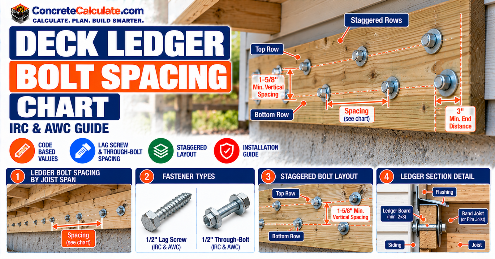
Deck Ledger Bolt Spacing ChartJoist Span, Bolts and Lag Screws
A code-based reference for deck builders, inspectors and homeowners: maximum ledger fastener spacing by joist span, lag screws versus through-bolts, staggered layout, edge and end distances, and the connections that spacing alone does not cover.
Jump to the Chart Reviewed by Muhammad Ramzan Babar, PhD Researcher (Plasma Physics) & Calculator Developer, View Profile
Key Facts
- Ledger bolt spacing is not 16 in. everywhere. For 12 ft joists on a solid-sawn band joist: 15 in. for 1/2 in. lag screws, 29 in. for 1/2 in. through-bolts (24 in. with 1 in. sheathing).
- Fasteners must be staggered, with at least 2 in. end distance and 1-5/8 in. between rows.
- The chart covers wood band joists only. Brick veneer, cantilevers and concrete need other solutions, and a lateral load connection is separate.
Deck Ledger Bolt Spacing Chart: Quick Reference
Bolt and lag screw spacing by joist span from the IRC.
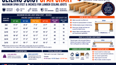
Deck ledger bolts are not all spaced at 16 inches. The permitted spacing depends on the joist span, the fastener type, the sheathing between the ledger and the house, and the house framing. This chart gives the IRC prescriptive schedule for a solid-sawn band joist. Joist spans themselves come from the Deck Joist Span Chart.
How to Read This Chart
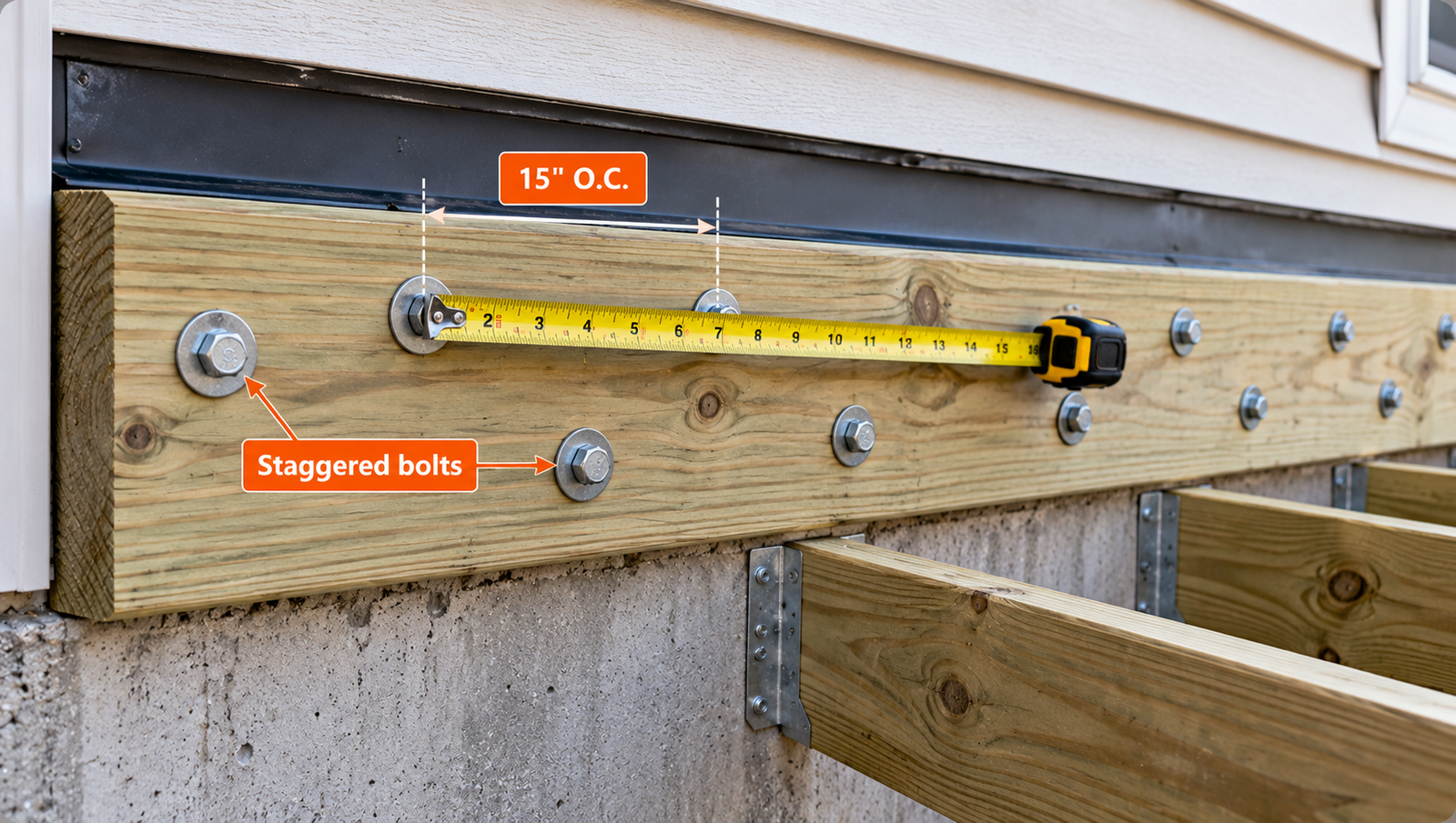
Find the span of your deck joists (the distance between the ledger and the outer beam), then read across for your fastener. Example: a deck with 12-foot joists on a qualifying solid-sawn band joist. 1/2 in. lag screws with 1/2 in. sheathing: 15 in. maximum. 1/2 in. through-bolts with 1/2 in. sheathing: 29 in. maximum. 1/2 in. through-bolts under the 1 in. sheathing configuration: 24 in. maximum. Do not pick the largest number without confirming its connection detail applies.
| Deck joist span | 1/2 in. lag screw, 1/2 in. max. sheathing | 1/2 in. through-bolt, 1/2 in. max. sheathing | 1/2 in. through-bolt, 1 in. max. sheathing |
|---|---|---|---|
| 6 ft or less | 30 in. | 36 in. | 36 in. |
| Over 6 to 8 ft | 23 in. | 36 in. | 36 in. |
| Over 8 to 10 ft | 18 in. | 34 in. | 29 in. |
| Over 10 to 12 ft | 15 in. | 29 in. | 24 in. |
| Over 12 to 14 ft | 13 in. | 24 in. | 21 in. |
| Over 14 to 16 ft | 11 in. | 21 in. | 18 in. |
| Over 16 to 18 ft | 10 in. | 19 in. | 16 in. |
- The schedule applies only to the stated details and loads. It is not a spacing chart for engineered rim boards, concrete, masonry or proprietary ledger screws.
- The 1 in. sheathing column has material and washer limits. It does not allow a 1 in. air gap or arbitrary cladding.
- Lag screw and through-bolt installation requirements differ. Fasteners must be staggered and meet the end, edge and row-spacing rules.
- Interpolation between spans is permitted; extrapolation is not.
- Higher loads, longer spans or unusual framing may need engineering. The adopted code edition, amendments and approved plans control.
Source: IRC Table R507.9.1.3(1), Deck Ledger Connection to Band Joist (2024 IRC, Section R507.9.1.3). The same values appear in the 2018 and 2021 editions. 40 psf live load, 10 psf dead load. Verify the complete footnotes in the code edition your jurisdiction has adopted.
What Is Deck Ledger Bolt Spacing?
Ledger Board Function
A deck ledger is the board that fastens the deck frame to the house. The deck joists hang from it, so it carries part of the deck’s weight into the house framing.
Center-to-Center Fastener Spacing
Spacing is measured from the center of one bolt or lag screw to the center of the next along the ledger. Code values are maximums.
Structural Load Transfer
The vertical load goes from the joist into the ledger, through the bolts or screws into the house band joist, and then into the house structure. The other end of each joist rests on a beam; see the Deck Beam Span Chart and the Deck Footing Size Chart for that part of the load path.
Deck Ledger Bolt Spacing Code Requirements
Two documents drive most ledger fastening: the International Residential Code and the American Wood Council’s DCA 6 deck guide.
| Section | What it covers |
|---|---|
| IRC R507.9.1.1 | Ledger: minimum nominal 2×8, No. 2 or better, pressure-treated or decay-resistant; no concentrated loads from beams; not on stone or masonry veneer |
| IRC R507.9.1.2 | Band joist: minimum 2 in. nominal solid-sawn SPF or better, or minimum 1 in. nominal engineered rim board; must bear fully on the primary structure |
| IRC R507.9.1.3 and Tables (1) and (2) | Ledger-to-band-joist fastening: spacing, hole sizes, edge and end distances |
| IRC R507.9.1.4 | Alternate ledger details that meet the load requirements of R301.5 |
| IRC R507.9.1.5 to R507.9.1.7 | Ledger flashing and water-resistive barrier |
| IRC R507.9.2 | Lateral connection (hold-down devices) |
IRC Section R507.9
R507.9 covers vertical and lateral supports at the band joist. The spacing table (Table R507.9.1.3(1)) is the source of this page’s main chart, and it also lists snow-load rows that the 40 psf live-load chart leaves out.
AWC DCA 6
The AWC Prescriptive Residential Wood Deck Construction Guide (DCA 6, 2015) repeats the IRC fastener schedules and adds rim-joist types and installation figures. A newer DCA 6 edition may exist, so check AWC.
Local Code Adoption and Amendments
The Adopted Code Controls
Each jurisdiction adopts a specific IRC edition and may amend it. The approved plans and the building official control. Do not combine values from different editions.
Deck Ledger Bolt Spacing by Joist Span
As the deck joists get longer, each joist delivers more load to the ledger, so the permitted spacing shrinks. The main chart shows the whole range; here are the patterns.
6- to 8-Foot Joists
Short joists allow the widest spacing: through-bolts at 36 in., lag screws at 30 in. (6 ft) or 23 in. (8 ft).
10- to 12-Foot Joists
Lag screws close to 18 in. and 15 in. Through-bolts open to 34 in. and 29 in. with 1/2 in. sheathing, or 29 in. and 24 in. with 1 in. sheathing.
14- to 18-Foot Joists
At 18 ft, lag screws are 10 in. apart and through-bolts 19 in. (16 in. with 1 in. sheathing). Check that the joist size and species actually allow that span, using the Deck Joist Span Chart.
1/2-Inch Deck Ledger Through-Bolt Spacing
Through-Bolt Connections
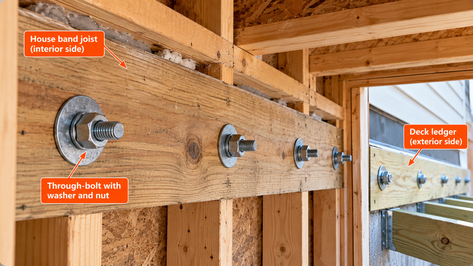
A through-bolt passes through the ledger, the sheathing and the band joist, and is secured with a nut and washers on the inside. The chart lists two through-bolt columns, for 1/2 in. and 1 in. maximum sheathing.
Washers and Nuts
Washers go under the head and under the nut. Stacked washers can stand in for up to 1/2 in. of sheathing in the 1 in. column when combined with wood structural panel or lumber sheathing, but not with gypsum or foam sheathing.
Prescriptive Spacing
The values run from 36 in. at short spans down to 16 in. to 19 in. at 18 ft, as the chart shows.
Proper Installation
Bolts must go completely through the ledger and band joist. The maximum distance between the ledger face and the band joist face is 1 in. Inside access to the band joist is needed.
Deck Ledger Lag Screw Spacing
Lag Screw vs. Bolt
A lag screw relies on its threads in the band joist, so the code allows less capacity per fastener than a through-bolt. A 1/2 in. lag screw is not interchangeable with a 1/2 in. through-bolt.
Pilot Holes
The IRC calls for predrilling with two bits: a 1/2 in. hole through the ledger and any sheathing, and a 5/16 in. to 3/8 in. hole through the band joist. Lag screws are turned in with a wrench or driver, not hammered.
Thread Penetration
The tip of the lag screw must fully extend beyond the inside face of the band joist, and lag screws must be full-body diameter screws. The AWC notes that a visible tip confirms the screw is the right length.
Spacing Schedule
The first column of the main chart gives the lag-screw schedule. A lag screw at a 12 ft span needs to be 15 in. on center; a through-bolt in the same condition can be 29 in. Lag sizes are in the Lag Bolt Sizes Chart.
Deck Ledger Bolt Spacing for Different Rim Joists
The spacing table assumes a solid-sawn band joist. Engineered rim joists change the numbers, as AWC’s Table 5 shows.
Solid-Sawn Lumber
A 1-1/2 in. solid-sawn band joist gives the widest spacing: 30 in. to 10 in. for lag screws and 36 in. to 19 in. for bolts.
| Fastener and receiving member | Up to 6 ft | Up to 8 ft | Up to 10 ft | Up to 12 ft | Up to 14 ft | Up to 16 ft | Up to 18 ft |
|---|---|---|---|---|---|---|---|
| 1/2 in. lag, 1 in. LVL | 24 | 18 | 14 | 12 | 10 | 9 | 8 |
| 1/2 in. lag, 1-1/8 in. LVL | 28 | 21 | 16 | 14 | 12 | 10 | 9 |
| 1/2 in. lag, 1-1/2 in. lumber | 30 | 23 | 18 | 15 | 13 | 11 | 10 |
| 1/2 in. bolt, 1-1/2 in. lumber | 36 | 36 | 34 | 29 | 24 | 21 | 19 |
Source: AWC DCA 6 (2015), Table 5. The through-bolt rows for LVL rim joists are not shown because they are not verified here.
LVL Rim Joists
A 1 in. LVL rim joist brings the 12 ft lag spacing down to 12 in. and a 1-1/8 in. LVL to 14 in., against 15 in. in solid lumber. Thinner rim members hold lag screws less well.
Engineered Rim Boards
The IRC says engineered rim joists follow the manufacturer’s recommendations, and it lets rim boards of at least 1 in. nominal serve as the band joist. Use the evaluated connection for the exact product.
Deck Ledger Board Size and Thickness
The ledger is a minimum nominal 2×8 of No. 2 grade or better, pressure-preservative-treated Southern pine, incised pressure-treated hem-fir, or decay-resistant wood.
2×8 Ledger
A 2×8 is 1-1/2 in. by 7-1/4 in. The staggered layout needs at least 2 in. at the top, 1-5/8 in. between rows and 3/4 in. at the bottom, a total of 4-3/8 in., so a 2×8 has room.
| Nominal size | Actual thickness | Actual depth | Role |
|---|---|---|---|
| 2×8 | 1-1/2 in. | 7-1/4 in. | Code minimum ledger |
| 2×10 | 1-1/2 in. | 9-1/4 in. | Common ledger |
| 2×12 | 1-1/2 in. | 11-1/4 in. | Deeper ledger |
2×10 and 2×12 Ledgers
Deeper ledgers give more room for the rows but do not change the table spacing. Actual sizes come from the Lumber Size Chart.
Minimum Prescriptive Requirements
A ledger may not carry concentrated loads from beams or girders, and it may not be supported on stone or masonry veneer.
Deck Ledger Bolt Staggering Pattern
Two-Row Staggered Layout
The IRC requires lag screws or bolts to be staggered from the top to the bottom along the horizontal run of the ledger, following its placement figure. Alternating between an upper and a lower row spreads the load and avoids splitting the ledger along a single grain line.
Alternating Fasteners
Consecutive fasteners alternate rows, so no two fasteners sit one above the other.
Horizontal Spacing
The on-center spacing in the chart is the maximum along the ledger. It does not change with the row you choose.
Vertical Row Spacing
Rows must be at least 1-5/8 in. apart. The placement figures, not the simplified table, set the upper and lower row locations. Do not invent fastener locations.
Deck Ledger Bolt Edge and End Distances
Top and Bottom Edge Clearances
The ledger and the band joist have different edge minimums because they sit at different heights.
| Measurement | Ledger | House band joist |
|---|---|---|
| Minimum top edge distance | 2 in. (see Figure R507.9.1.3(1)) | 3/4 in. |
| Minimum bottom edge distance | 3/4 in. | 2 in. |
| Minimum end distance | 2 in. (maximum 5 in.) | 2 in. |
| Minimum spacing between rows | 1-5/8 in. | 1-5/8 in. |
Source: IRC Table R507.9.1.3(2) and Figures R507.9.1.3(1) and (2), 2024 IRC; same values in the 2018 and 2021 editions.
Ledger End Distances
Fasteners must sit at least 2 in. from the ends, and the table footnote caps that distance at 5 in.
House Band-Joist Clearances
The band joist needs 3/4 in. at the top and 2 in. at the bottom. For engineered rim joists, the manufacturer’s recommendations govern.
Deck Ledger Bolt Spacing With Sheathing
1/2-Inch Sheathing
The lag screw column and the first bolt column assume sheathing up to 1/2 in. thick. The sheathing must be wood structural panel or solid-sawn lumber.
1-Inch Sheathing
The third column covers up to 1 in. of sheathing, which can be wood structural panel, gypsum board, fiberboard, lumber or foam sheathing. It carries closer spacing.
Stacked Washer Conditions
Up to 1/2 in. of stacked washers can replace up to 1/2 in. of allowable sheathing thickness where combined with wood structural panel or lumber sheathing. The AWC notes stacked washers are not permitted with gypsum board or foam sheathing.
Prohibited Substitutions
The maximum distance between the ledger face and the band joist face is 1 in. Do not treat thick siding or cladding as structural sheathing.
Deck Ledger Bolt Size and Material
1/2-Inch Fasteners
The prescriptive tables are written for 1/2 in. bolts and lag screws. Fastener dimensions are in the Lag Bolt Sizes Chart.
Hot-Dip Galvanized Hardware
Fasteners and connectors in contact with preservative-treated wood must be hot-dipped zinc-coated galvanized steel or another corrosion-resistant material under the code’s fastener provisions (Section R507.2.3 for deck fasteners).
Stainless Steel
Stainless steel is used for higher corrosion exposure. Do not mix galvanized and stainless components in contact.
Treated-Wood Compatibility
Use the approved ledger hardware. A general Bolt Grade Chart describes bolt material but does not make a bolt an approved ledger fastener.
How to Calculate Deck Ledger Bolt Quantity
Ledger Length and Maximum Spacing
Start with the ledger length and the maximum spacing from the chart for your span and fastener.
End Offsets
Keep each end offset between 2 in. and 5 in. The examples use 3 in.
Worked Example
Preliminary Fastener Count
Variables: L = ledger length; e = end offset; s = maximum spacing; N = fastener positions
Practical interpretation: The real layout alternates rows, keeps the end and edge distances, and avoids unsuitable framing locations.
Actual Even Spacing
Variables: Same variables
Practical interpretation: Geometry only. Check the staggered pattern and placement before drilling.
Counts for the Same Ledger
| Connection | Max. spacing (12 ft joists) | Fastener positions | Even spacing |
|---|---|---|---|
| 1/2 in. lag screw, 1/2 in. sheathing | 15 in. | 14 | 14.31 in. |
| 1/2 in. bolt, 1/2 in. sheathing | 29 in. | 8 | 26.57 in. |
| 1/2 in. bolt, 1 in. sheathing | 24 in. | 9 | 23.25 in. |
Deck Ledger Load Calculations
Deck Area Loads
Design loads come from the code and the deck use. See the Deck Load Chart for live, dead and snow load values.
Joist Tributary Load
Tributary Load on the Ledger
Variables: w = line load on the ledger (plf); q = area load (psf); Lj = joist span (ft)
Practical interpretation: Simplified for joists simply supported between the ledger and an outer beam. Cantilevers and concentrated loads change the reaction.
Ledger Reaction
Total Ledger Reaction
Variables: R = total vertical reaction; Lledger = ledger length
Practical interpretation: This is not the capacity needed from each fastener.
Why Longer Joists Need Closer Spacing
The line load rises in direct proportion to the joist span, which is why the spacing tightens.
| Joist span | Ledger line load (derived) |
|---|---|
| 8 ft | 200 plf |
| 10 ft | 250 plf |
| 12 ft | 300 plf |
| 14 ft | 350 plf |
| 16 ft | 400 plf |
Do not convert these loads into a fastener spacing with an invented bolt capacity. The IRC table already does that for the stated details.
Deck Ledger Bolt Spacing for 12-Foot and 16-Foot Decks
Identifying the Actual Joist Span
Use the span of the deck joists, from the ledger to the outer beam. Deck depth and ledger length are not the same thing, and neither is the joist’s overall length if it cantilevers.
Selecting the Correct Table Column
Choose the span row, then the fastener and sheathing column that match your connection. For 12 ft joists use the ‘over 10 to 12 ft’ row: 15, 29 or 24 in. For 16 ft joists use the ‘over 14 to 16 ft’ row: 11, 21 or 18 in.
Comparing Bolt and Lag Spacing
Through-bolts with 1/2 in. sheathing allow about twice the lag spacing at 12 ft (29 in. versus 15 in.) and about 1.9 times at 16 ft (21 in. versus 11 in.).
Deck Ledger Connections to Concrete and Masonry
The wood-band-joist table does not apply to concrete or masonry.
Concrete Foundation Walls
A ledger on a poured concrete foundation needs approved anchors and an anchorage design. Spacing and edge distance come from the anchor’s evaluation, as in the Concrete Anchor Spacing Chart.
Solid Masonry
Solid masonry also needs engineered anchorage. Hollow masonry requires a specifically approved solution.
Approved Expansion and Adhesive Anchors
Use anchors approved for the base material. General anchor sizes are in the Anchor Bolt Size Chart.
Anchor Embedment and Edge Distance
Embedment, edge distance and spacing depend on the exact product. The IRC allows alternate ledger details that meet its load requirements (R507.9.1.4).
Deck Ledger Attachment to Brick Veneer and Cantilevers
Brick and Stone Veneer
The IRC says a deck ledger may not be supported on stone or masonry veneer. Veneer is not a structural support.
Hollow Masonry
Hollow masonry needs an approved engineered connection.
Cantilevered Floor Overhangs
The band joist must bear fully on the primary structure. A floor that cantilevers past the wall, or a bay window, does not qualify, and AWC DCA 6 prohibits the prescriptive ledger connection there.
Freestanding Deck Alternative
Where the house cannot support a ledger, a freestanding deck with its own posts and beams avoids the problem.
| House attachment condition | Prescriptive approach |
|---|---|
| Qualifying solid-sawn band joist | IRC or AWC ledger table, subject to all conditions |
| Specified LVL rim joist | AWC or manufacturer-approved detail |
| Proprietary engineered rim board | Manufacturer-approved or engineered connection |
| Concrete foundation wall | Approved anchor design |
| Solid masonry | Approved engineered anchorage |
| Brick or stone veneer | Do not attach the ledger to the veneer |
| Hollow masonry | Requires a specifically approved engineered solution |
| Cantilevered floor overhang | Conventional prescriptive ledger connection prohibited |
| Inadequate existing house framing | Consider a freestanding deck |
Deck Ledger Lateral Load Connections
Vertical vs. Lateral Resistance
Ledger bolts resist vertical load. A deck also needs a lateral load path so it does not pull away from or slide along the house. The ledger spacing chart does not cover that.
1,500-Pound Hold-Down Option
Where the IRC’s first lateral detail is used, hold-down tension devices go in at least two locations per deck, within 24 in. of each end of the deck, and each device must have an allowable stress design capacity of at least 1,500 lb.
750-Pound Hold-Down Option
Where the second detail is used, hold-downs go in at least four locations per deck and each must be rated for at least 750 lb.
Manufacturer-Approved Details
These alternatives have placement and installation requirements of their own, and engineered floor systems such as I-joists need the floor manufacturer’s lateral-connection detail. Use hold-downs approved for the purpose.
Deck Ledger Flashing and Waterproofing
Continuous Flashing
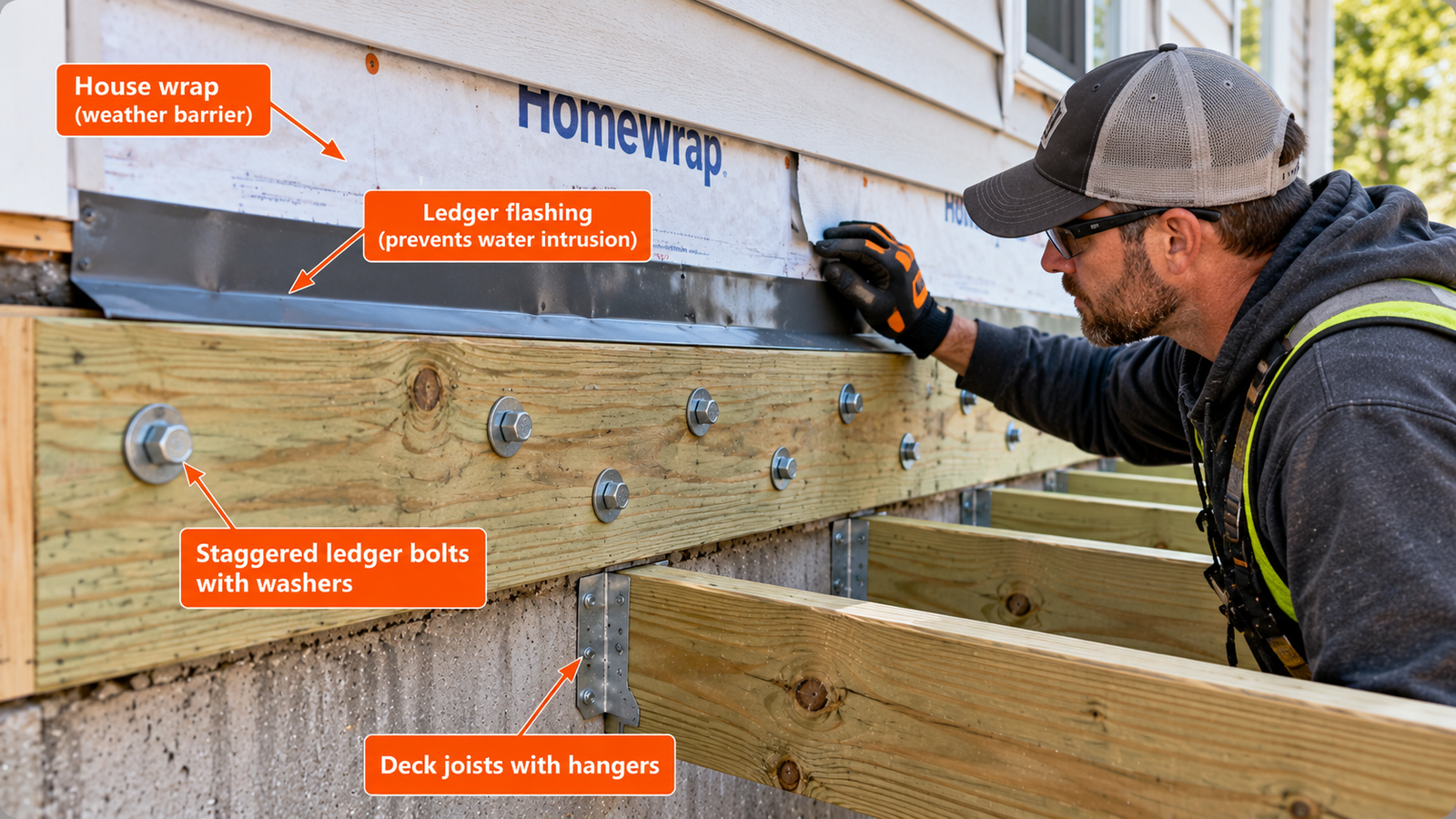
Where a ledger is attached to wood-frame construction, flashing goes above the ledger. It must extend at least 2 in. above the ledger vertically and at least 4 in. horizontally beyond the ledger face, or reach the ledger face and turn down at least 1/4 in. A window or door within 2 in. above the ledger means the flashing runs to the bottom of that opening.
Water Intrusion
The water-resistive barrier is lapped over the vertical flashing leg at least 2 in. Existing walls without a barrier need one installed behind the ledger and flashing.
Ledger Deterioration
Flashing is not required where the ledger stands off the wall covering at least 1/4 in. for drainage and ventilation. Water that gets behind a ledger can rot the band joist and defeat a correctly spaced connection.
Inspection
Check the flashing and the wood behind the ledger whenever you inspect a deck.
How to Install Deck Ledger Bolts Correctly
Confirm House Framing
- Confirm the house framing and the band joist type.
Mark Bolt Locations and Drill
- Mark bolt locations on the ledger in a staggered layout.
- Drill the correct holes: clearance holes for bolts, or two-bit predrilling for lag screws.
Install Bolts or Lag Screws and Washers
- Install the bolts or lag screws with washers.
- Tighten the hardware.
Inspect and Tighten
- Inspect the connection and the flashing.
Turn lag screws in; do not hammer them. Washers go under heads and nuts. Do not use a universal tightening torque; follow the governing details. Joist-to-ledger connections use approved hangers; see the Joist Hanger Size Chart.
Structural Ledger Screws as Alternatives
Proprietary Structural Screws
Structural ledger screws are tested products with their own geometry, hole requirements and spacing tables. One manufacturer’s ledger screw guide, for instance, specifies a 3-3/4 in. minimum end distance and a 1-3/4 in. minimum edge distance in a V-shaped stagger, which differ from the IRC bolt values.
Manufacturer Spacing Tables
Each product publishes spacing by joist span and rim material. Use only that table, not the bolt chart.
Approved Substitution
Substitution is allowed only where the product’s evaluation report or the code approves it for the exact ledger and band joist.
Evaluation Reports
Do Not Swap Screws Into the Bolt Chart
Do not substitute proprietary screws (SDWS, SDS or others) into the 1/2 in. bolt and lag chart. Use the manufacturer’s table and evaluation report.
Deck Ledger Connections in High-Load Conditions
Snow Loads
The main chart uses a 40 psf live load. The IRC table also has rows for 50, 60 and 70 psf ground snow loads, which tighten the spacing as the table below shows.
| Joist span | 40 psf live load | 50 psf ground snow | 60 psf ground snow | 70 psf ground snow |
|---|---|---|---|---|
| 12 ft | 15 / 29 / 24 | 14 / 27 / 23 | 12 / 23 / 20 | 11 / 20 / 17 |
| 18 ft | 10 / 19 / 16 | 9 / 18 / 15 | 8 / 15 / 13 | 7 / 13 / 11 |
Source: IRC Table R507.9.1.3(1), 2024 IRC. See the table for the other joist spans.
Hot Tubs and Concentrated Loads
The table does not cover hot tubs, planters, heavy furniture or other concentrated loads. They need engineering. Load values are in the Deck Load Chart.
Roofed Decks
A roof over a deck adds roof and snow loads that the table does not include.
Engineered Connection Requirements
Ordinary 40 psf live load schedules can be insufficient in these conditions. Use an engineered connection.
Existing Deck Ledger Inspection and Retrofitting
Missing or Undersized Fasteners
Count the fasteners and compare them with the chart, but also check the type, diameter, washers and penetration. For lag screws, the tip should show beyond the inside face of the band joist.
Wood Rot
Probe the ledger and band joist, especially at the top edge behind flashing. A correctly spaced connection in rotted wood is not safe.
Corrosion
Look for corroded or missing hardware, and for galvanized or stainless fasteners that do not match their connectors.
Reinforcement Options
Adding bolts does not repair a deteriorated ledger connection. Replace damaged wood, restore flashing and add lateral connections, or build a freestanding deck.
Common Deck Ledger Bolt Spacing Mistakes
Incorrect Spacing
Using 16 in. spacing for every deck
The span, fastener and rim joist set the value.
Mixing up lag screw and bolt columns
They have different spacing.
Counting stacked washers as free
Only with allowed sheathing types.
Wrong Fasteners
Using the wrong hardware
Use 1/2 in. bolts or lag screws as the table specifies.
Skipping pilot holes
Lag screws need the two-bit pilot holes.
Leaving out washers
Washers go under heads and nuts.
Missing Staggering
Installing one in-line row
The pattern must be staggered.
Ignoring end and edge distances
Follow Table R507.9.1.3(2).
Inadequate House Connection and Poor Flashing
Attaching to brick veneer
Veneer is not structural support.
Attaching to a cantilevered floor
Prescriptive ledger attachment is prohibited there.
Neglecting lateral loads
Hold-downs are a separate requirement.
Skipping flashing
Water destroys the band joist.
Deck Ledger Connection Inspection Checklist
Fastener Layout
Verify spacing, staggering, and end and edge clearances against the chart and Table R507.9.1.3(2).
| Check | Required verification |
|---|---|
| Joist span | Correct span category |
| Loads | Applicable live, dead, snow and concentrated loads |
| Ledger | Minimum permitted size and condition |
| House rim | Structural type, thickness and condition |
| Fasteners | Correct diameter, material and type |
| Spacing | Maximum on-center spacing satisfied |
| Layout | Staggered rows, end and edge clearances |
| Installation | Correct pilot holes, washers and penetration |
| Flashing | Water managed behind the ledger |
| Lateral loads | Separate compliant load path |
| Approval | Local code and approved construction details |
Structural Support
Check the house band joist and its support below.
Corrosion and Flashing
Check the hardware finish and the flashing.
Code Verification
Confirm the adopted code edition and the approved plans.
Deck Ledger Bolt Spacing FAQs
Spacing and Fasteners
How far apart should ledger bolts be?
It depends on joist span, fastener and sheathing. For 12 ft joists on a solid-sawn band joist, 1/2 in. lag screws go no more than 15 in. apart and 1/2 in. through-bolts 29 in. (24 in. with 1 in. sheathing). See the main chart.
Is 16 inches on center required?
No. 16 in. is not a code value. Spacing is read from the table by joist span and fastener.
What size bolts are used?
The IRC and AWC tables are written for 1/2 in. lag screws and through-bolts.
Do ledger bolts need to be staggered?
Yes, the IRC requires lag screws and bolts to be staggered top to bottom along the ledger, with 1-5/8 in. minimum between rows and the required end and edge distances.
Can a ledger attach to brick?
No. A ledger may not be supported on stone or masonry veneer. Use a freestanding deck or an engineered connection into the structure.
How many bolts does a 16-foot ledger need?
With 12 ft joists, about 14 lag screws at 15 in., or about 8 to 9 through-bolts at 29 in. or 24 in., using 3 in. end offsets. These are layout counts, not a structural design.
Can structural screws replace bolts?
Only where the screw’s own tested spacing table and evaluation report approve it for your ledger and band joist. Do not substitute them into the bolt chart.
Are lateral hold-downs required?
Yes, a lateral load connection is required. The IRC details use two hold-downs rated at least 1,500 lb each, or four rated at least 750 lb each.
What size ledger board is required?
A minimum nominal 2×8, No. 2 grade or better, pressure-preservative-treated or decay-resistant.
What holes do lag screws need?
The IRC calls for a 1/2 in. hole through the ledger and sheathing and a 5/16 in. to 3/8 in. hole through the band joist.
Does a ledger need flashing?
Yes, where it is attached to wood-frame construction, unless it is spaced at least 1/4 in. from the wall covering for drainage. Flashing extends at least 2 in. above the ledger.
Can I rely on the chart for a deck with a hot tub?
No. Concentrated loads and higher loads need engineering.
Sources and Scope Limits
Correct Spacing Alone Does Not Make a Ledger Safe
The house framing, fastener installation, staggered layout, lateral-load resistance, corrosion protection, flashing and the complete load path must all be satisfactory. This chart does not establish adequate joist spans, beam and footing sizes, anchorage to concrete, house framing adequacy, or compliance with higher snow or occupancy loads. The adopted code edition, approved plans and building official control.
Primary References
- 2024 International Residential Code, Chapter 5, Floors (ICC)
- AWC DCA 6, Prescriptive Residential Wood Deck Construction Guide (2015)
- AWC, Is Your Deck Safely Connected to Your House?
- ICC Building Safety Journal, Is Your Deck Safely Connected to Your House?
- Weyerhaeuser, Deck Lateral Load Connection to a TJI Floor System
- Simpson Strong-Tie, ledger and structural screw literature
Download Deck Ledger Bolt Spacing Chart PDF
Use your browser’s print function to save this page as a PDF for jobsite binders and permit files. The printed version hides interactive elements and keeps the tables.