Column Size Chart – Material, Load, Height & Bracing Guide
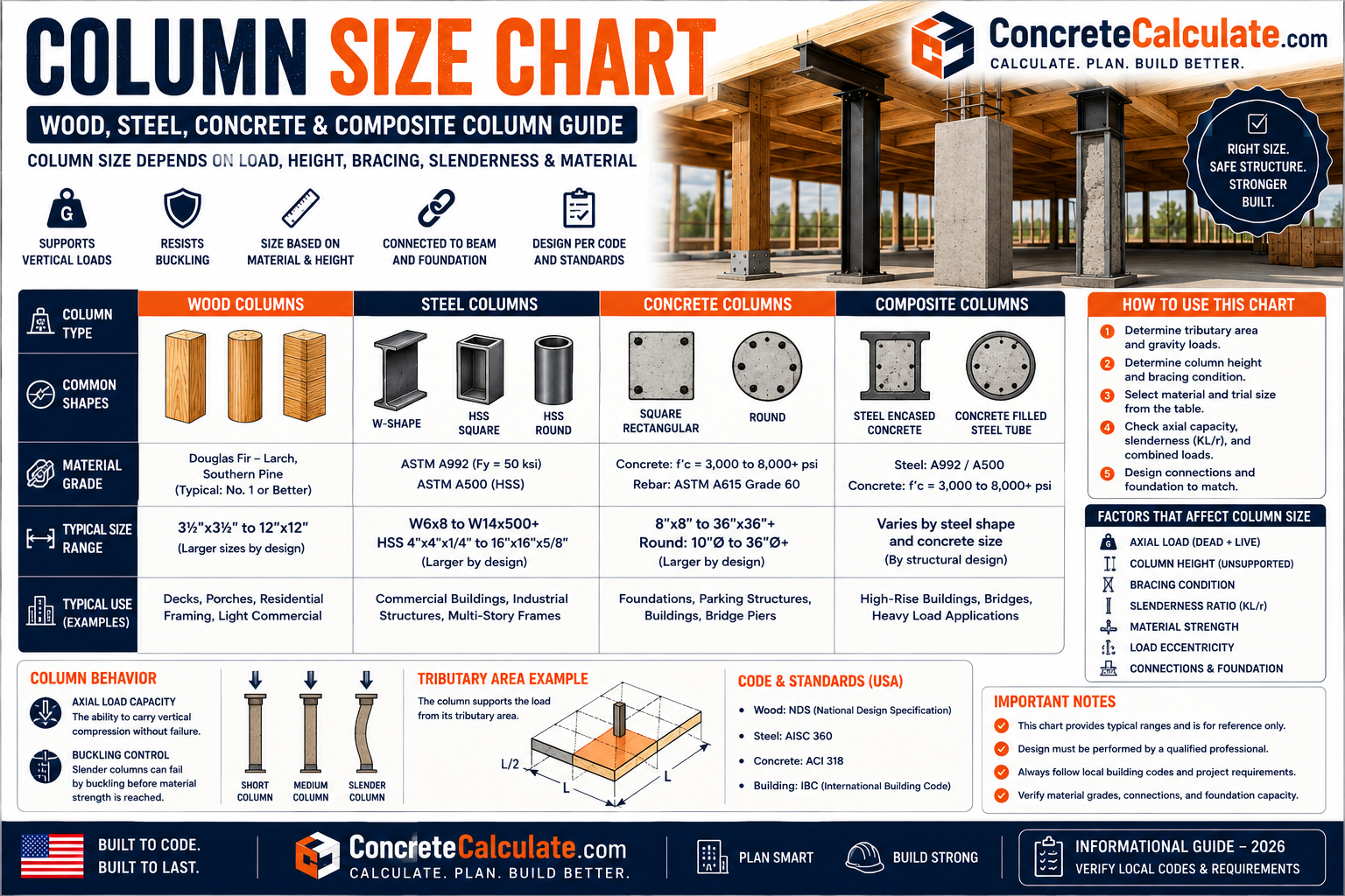
Column Size Chart
Material, Load, Height & Bracing Guide
A column’s required size depends on material, cross-section, unsupported height, bracing, load, eccentricity and connections, not on a size label alone.
 Reviewed by Muhammad Ramzan Babar, PhD Researcher & Calculator Developer · View Profile
A statement such as “a 6×6 post holds 10,000 lb” or “a W8 column supports 50 kips” is incomplete without stated height, bracing, material grade, effective length and connection details. Use this page for planning concepts only, and obtain a qualified structural design for actual construction.
⭐ Column Size Chart: Quick Reference
A column is a vertical member that carries axial compression, and sometimes bending, down a gravity load path to the foundation. These categories are reference starting points, not universal allowable-load values.
| Column Material | Column Size | Shape | Load | Height | Bracing | Application |
|---|---|---|---|---|---|---|
| Wood | Species/grade dependent | Square/rectangular | Project-specific axial load | Unsupported height governs slenderness | Braced | Residential |
| Steel | Shape/grade dependent | W-shape / HSS / pipe | Project-specific axial load | Unbraced length governs KL/r | Braced or unbraced | Structural |
| Reinforced concrete | Dimension + reinforcement dependent | Square/rectangular/round | Project-specific axial and bending load | Unsupported length affects slenderness | Design-dependent | Structural |
| Composite | Product/design dependent | Steel + concrete (filled or encased) | Project-specific combined load | Unbraced length governs interaction checks | Design-dependent | Structural |
Wood guidance references the current 2024 NDS. Steel guidance references AISC’s current Shapes Database v16.0 and 16th Edition Manual, keyed to the 2022 AISC Specification. Concrete guidance references ACI CODE-318-25. Composite guidance references AISC Design Guide 6, updated for filled and encased composite columns under the 2022 Specification.
⭐ What Is a Structural Column?
A column is a primary vertical structural member designed mainly to resist axial compression and transfer gravity loads down to the foundation.
Load transfer
Columns receive load from beams, slabs, or roof framing above and carry it, along with their own weight, down to a footing or foundation element bearing on soil.
Column vs post
Post is common terminology in residential wood framing; column is common in general structural terminology. Both perform the same structural role and need the same design checks.
Column vs pier
Pier often refers to a short, stocky concrete or masonry support, sometimes below grade or partially embedded, while column more often describes a taller freestanding compression member.
Column vs beam
A beam primarily resists bending and shear along a horizontal span. A column primarily resists axial compression, buckling and sometimes combined axial plus bending.
Roof or floor load transfers to a beam, the beam reaction transfers to a column, the column transfers its accumulated load to a base connection, then to a footing, and finally to bearing soil.
⭐ Column Size vs Column Capacity
A larger-looking column is not automatically adequate. Capacity is a function of several interacting variables, not cross-sectional area alone.
| Variable | Why It Affects Capacity |
|---|---|
| Material | Wood, steel, concrete and composite have fundamentally different strength and stiffness behavior |
| Cross-section | Area, moment of inertia and radius of gyration govern strength and buckling resistance |
| Unsupported length | Longer unbraced lengths increase slenderness and reduce buckling capacity |
| Slenderness | Combines length and section geometry into a single stability indicator |
| Bracing | Lateral restraint reduces effective length and can significantly increase capacity |
| Load | Magnitude, duration and type of load change which design check governs |
| Eccentricity | Off-center or combined bending loads reduce pure axial capacity |
| Connections | The base, cap and beam connections must also be adequate for the actual reactions |
⭐ Master Column Size Chart by Material
Organizing columns by material avoids mixing incompatible design bases into one misleading table.
Wood columns
Common residential sizes: 4×4, 4×6, 6×6, 6×8, 8×8 and larger structural timber posts. Capacity depends on species, grade, unbraced length and load per the current NDS.
Steel columns
Common families: W-shapes, square HSS, rectangular HSS, round HSS and pipe. Capacity depends on shape, steel grade, unbraced length, effective length factor K and slenderness KL/r.
Reinforced concrete columns
Common shapes: square, rectangular and round, often ranging from around 8×8 up to 20×20 inches or larger. Capacity depends on concrete strength, reinforcement, dimensions and slenderness per ACI 318.
Composite columns
Includes concrete-filled steel HSS, concrete-encased steel shapes, and composite W-shapes in square, rectangular or round forms. Capacity depends on the steel-concrete interaction per AISC Design Guide 6.
⭐ Wood Column Size, Load, Height, Species & Grade
Wood-column capacity depends on species, grade, unbraced length and loading, referenced against the current 2024 NDS, which covers sawn lumber and other wood structural products.
| Common Size | Typical Residential Role | Required Design Basis |
|---|---|---|
| 4×4 | Light deck or porch posts | Species, grade, height, bracing and actual load |
| 4×6 | Light to moderate beam support | Orientation, species, grade and slenderness check |
| 6×6 | Common residential post size | Do not assume one universal capacity for every 6×6 |
| 6×8 | Heavier beam or roof support | Verify bearing area and connection detail |
| 8×8 | Heavier structural posts | Confirm species/grade design values and height |
| Larger structural timber | Heavy load or architectural applications | May require engineered wood or a qualified design |
Post vs column terminology
Deck posts, porch posts, interior posts, roof-support posts and beam-support posts are all functioning as columns and need the same design checks regardless of the word used.
Species and grade
Southern Pine, Douglas Fir-Larch, Hem-Fir, Spruce-Pine-Fir and other commercially graded species groups have different reference compression design values. Grade further changes those values.
| Unsupported Height | Slenderness Effect |
|---|---|
| 6 ft | Lower slenderness ratio for a given cross-section |
| 8 ft | Moderate increase in slenderness |
| 10 ft | Continued increase; verify against NDS slenderness limits |
| 12 ft | Higher slenderness; bracing becomes more valuable |
| 14 ft | Approaching typical practical limits for common post sizes |
| 16 ft+ | May require a larger section, bracing, or engineered alternative |
The current NDS limits the slenderness ratio for solid wood columns, effective length divided by cross-sectional dimension, to 50 for normal loading, and 75 during construction. This is why increasing unsupported height can significantly reduce a wood column’s allowable load even without changing its cross-section.
⭐ Steel Column Size: W-Shapes, HSS & Pipe
AISC’s current Shapes Database v16.0 provides section dimensions and properties consistent with the 16th Edition Steel Construction Manual, covering W-shapes and hollow structural sections.
| Steel Column Family | Typical Shape Description | Key Section Properties |
|---|---|---|
| W-Shapes | Wide-flange rolled shapes | Depth, weight, area, moment of inertia, radius of gyration |
| Square HSS | Hollow structural section, square profile | Outside dimension, wall thickness, area, weight |
| Rectangular HSS | Hollow structural section, rectangular profile | Outside dimensions, wall thickness, area, weight |
| Round HSS | Hollow structural section, round profile | Outside diameter, wall thickness, area, weight |
| Steel Pipe | Circular hollow section, often pipe-schedule based | Outside diameter, wall thickness, area, weight |
Pipe vs HSS terminology
Round HSS and steel pipe are similar in shape but are often specified through different standards, dimension conventions and design tables. Confirm which product is actually being specified.
W-shape design
Do not turn a W-shape into a universal capacity claim without stating column length, bracing, steel grade and design method. AISC maintains dedicated compression tables for W-shapes and HSS.
| Preliminary Load Range | Required Additional Inputs |
|---|---|
| 10, 20, 30 kip | Column length, steel grade, bracing condition and effective length |
| 50, 75, 100 kip | Same inputs plus connection and base plate verification |
| 150, 200 kip and above | Design method, load combinations and often a full engineered design |
AISC’s preliminary column tables are specifically intended for early-stage approximate sizing and are not a substitute for structural engineering services on an actual project.
⭐ Column Buckling & Slenderness Ratio
Buckling, not material crushing, often governs how much axial load a column can carry, especially for longer, more slender members.
Euler buckling concept
A slender column can fail by sudden lateral instability at a load lower than its pure material compressive strength, driven by length and stiffness rather than material crushing alone.
Critical buckling load
The theoretical load at which a perfectly straight, ideally supported column would buckle, used as a foundation for practical design equations with additional safety and imperfection considerations.
Radius of gyration
A section property describing how a cross-section’s area is distributed relative to a given axis, directly affecting buckling resistance about that axis.
Slenderness ratio (steel)
Calculated as KL/r, where K is the effective length factor, L is the unbraced length, and r is the radius of gyration. Higher KL/r generally reduces allowable axial stress.
| End Condition | Sidesway | Typical K Range |
|---|---|---|
| Both ends pinned | Prevented | Approximately 1.0 |
| Fixed base, pinned top | Prevented | Approximately 0.7 to 0.8 |
| Fixed base, free top (cantilever) | Permitted | Approximately 2.0 or more |
| Column in a moment frame | Permitted | Often 1.2 to 2.5 depending on relative stiffness |
AISC guidance indicates K should be taken as unity for columns in braced frames unless analysis justifies a smaller value, while unbraced frame columns require an alignment chart or software analysis and are typically greater than 1.0, often 1.2 to 2.5. Using K = 1.0 for an unbraced frame column is unconservative.
⭐ Reinforced Concrete Column Size, Load & Reinforcement
Concrete column capacity depends on concrete strength, reinforcement, dimensions, unsupported length, load eccentricity and slenderness, per the current ACI CODE-318-25 Building Code Requirements for Structural Concrete.
| Shape | Common Dimension Range | Design Basis Needed |
|---|---|---|
| Square | 8×8 to 20×20 in and larger | Concrete strength, reinforcement ratio, unsupported length, eccentricity |
| Rectangular | 12×16, 12×18 and larger | Same as square, plus axis-specific slenderness check |
| Round | Diameter-based sizing | Same variables, typically with spiral reinforcement |
A statement like “12×12 concrete column equals X pounds” ignores reinforcement ratio, concrete strength, slenderness and eccentricity, all of which materially change actual capacity under ACI 318.
| Reinforcement Element | ACI 318-25 Reference Point |
|---|---|
| Minimum longitudinal bars, rectangular/circular ties | At least 4 bars |
| Minimum longitudinal bars, spiral columns | At least 6 bars |
| Minimum longitudinal bars, triangular ties | At least 3 bars |
| Tie spacing (center to center) | Least of 16 times longitudinal bar diameter, 48 times tie bar diameter, or smallest column dimension |
| Minimum spiral bar/wire diameter | At least 3/8 in for cast-in-place construction |
| Spiral clear spacing | At least the greater of 1 in and 4/3 of aggregate size, not more than 3 in |
Tied columns
Longitudinal bars are held by individual ties at intervals, a common and economical detailing approach for many rectangular and square columns.
Spiral columns
Longitudinal bars are enclosed by a continuous spiral, which can improve ductility and confinement, commonly used in some round columns and higher-demand applications.
See the Rebar Size Chart, Rebar Grade Chart and Concrete Cover Chart for related reinforcement detailing.
⭐ Composite Column Size Chart
Composite columns combine steel and concrete to use both materials’ strengths. AISC’s Design Guide 6 was updated to cover square, rectangular and round filled composite columns along with encased composite columns under the 2022 AISC Specification.
| Composite Type | Description | Typical Shape |
|---|---|---|
| Filled composite (HSS) | Hollow structural section filled with concrete, sometimes with added reinforcement | Square, rectangular or round |
| Encased composite | Wide-flange steel shape surrounded by reinforced concrete | Typically rectangular overall section |
| High-strength filled | Filled composite using higher-strength materials for greater capacity in a smaller footprint | Square, rectangular or round |
Composite column strength is calculated using specification provisions for axial, flexural, shear and interaction strength across encased, filled and high-strength filled member types. It is not simply the steel capacity plus the concrete capacity added together.
⭐ Column Size by Material & Application
Different materials suit different applications, exposures, and design philosophies.
| Material | Common Column Forms | Main Design Factors |
|---|---|---|
| Wood | Square/rectangular | Species, grade, unbraced length, slenderness limit |
| Steel | W/HSS/pipe | Buckling, KL/r, grade, connections |
| Concrete | Square/rectangular/round | Reinforcement, strength, slenderness, eccentricity |
| Composite | HSS filled or encased steel | Steel-concrete interaction, connections |
Basement columns
Support beams carrying floor loads above; determine tributary area, floor load, and column height, then verify foundation support. See the Beam Size Chart and Footing Size Chart.
Deck and porch columns
Support deck or porch beams and roof loads; consider exterior exposure, post height, bracing and footing. See the Deck Beam Span Chart and Deck Footing Size Chart.
Garage columns
Support beams above large openings and roof loads. Vehicle-related layouts may add clearance and impact-protection considerations beyond pure gravity design.
Commercial and industrial columns
Typically involve steel, concrete or composite construction with higher loads, multiple floors and more rigorous code-driven design requirements.
⭐ Column Tributary Area & Load Calculation
Tributary area is the floor or roof area whose load is assigned to a specific column, based on framing geometry.
Tributary area multiplied by design load per square foot gives an approximate column gravity load. Add dead load, live load, roof load, and snow load where applicable, and account for accumulated load from multiple floors. This is a preliminary concept, not a complete column design, since load combinations and code provisions still govern final design.
| Number of Floors Supported | Load Accumulation Concept |
|---|---|
| One floor | Column carries only that floor’s tributary load plus self-weight |
| Two floors | Lower column receives accumulated load from both floors above |
| Three floors | Ground-level or foundation columns can carry substantially more accumulated load |
Beam reactions
A column often receives a concentrated beam reaction rather than a simple uniform floor load. Bearing area and possible eccentricity at that connection must be checked.
Point loads and roof effects
Truss reactions, posts above, and roof dead, snow and wind effects can all contribute point loads or additional demand beyond a basic tributary-area estimate.
⭐ Column Eccentric Loading, Bracing & Slenderness
Real columns are rarely loaded perfectly concentrically, and lateral restraint significantly changes effective behavior.
Eccentric loading
An off-center axial load or an applied moment creates combined axial-plus-bending behavior, which reduces the pure axial capacity otherwise available at that load level.
Braced vs unbraced columns
A braced column has its ends and possibly its length restrained against lateral movement, generally producing a smaller effective length than an unbraced column of the same physical height.
Short vs slender columns
A short, stocky column and a tall, slender column can have similar cross-sectional area yet very different compression capacity, because slenderness reduces buckling resistance disproportionately as height increases.
Design implication
Always check both material strength and buckling/stability limits. A column can fail by buckling well before its cross-section reaches material crushing capacity.
⭐ Column Foundation, Base Plates & Connections
A properly sized column does nothing if its connections and foundation cannot safely receive its reactions.
Load path to soil
Column reaction transfers through a base connection to a footing, which then transfers load to bearing soil. Each link in that chain needs its own verification.
Steel base plates
Base plates distribute a concentrated column reaction over a larger bearing area on concrete, and are typically anchored with bolts sized for shear, tension and uplift. See the Base Plate Calculator and Anchor Bolt Size Chart.
Connections by material
Wood column-to-beam, steel column-to-beam, steel column base, and concrete column-to-footing connections each have distinct detailing requirements that must be checked separately from the column member itself.
Footing sizing
Footing size depends on the actual column load and allowable soil bearing pressure, not column dimensions. See the Footing Size Chart.
Column Fire Resistance, Corrosion & Concrete Cover
Protection requirements are system-specific and should not be inferred from column dimensions alone.
| Material | Protection Consideration |
|---|---|
| Wood | Fire resistance depends on required assembly, char behavior and code-specified rating, not simply post size |
| Steel | Often requires fireproofing, and exterior or humid exposure requires coatings or corrosion-resistant detailing |
| Concrete | Concrete cover over reinforcement affects both fire resistance and corrosion protection; connect column dimensions, reinforcement layout and required cover |
| Composite | Fire and corrosion performance depend on the specific filled or encased configuration and any added protection |
See the Concrete Cover Chart for reinforced concrete cover requirements linked to column dimensions and reinforcement.
⭐ Column vs Post, Beam & Footing
Clarifying terminology and structural roles helps avoid design confusion.
| Comparison | Key Distinction |
|---|---|
| Column vs post | Largely interchangeable terms; post is common in residential wood construction, column in general structural usage |
| Column vs beam | Beam primarily resists bending and shear; column primarily resists compression, buckling and combined axial plus bending |
| Column vs footing | A properly sized column does not automatically mean the footing is adequate; footing size depends on load and soil bearing capacity |
See the Beam Size Chart and Footing Size Chart for related design references.
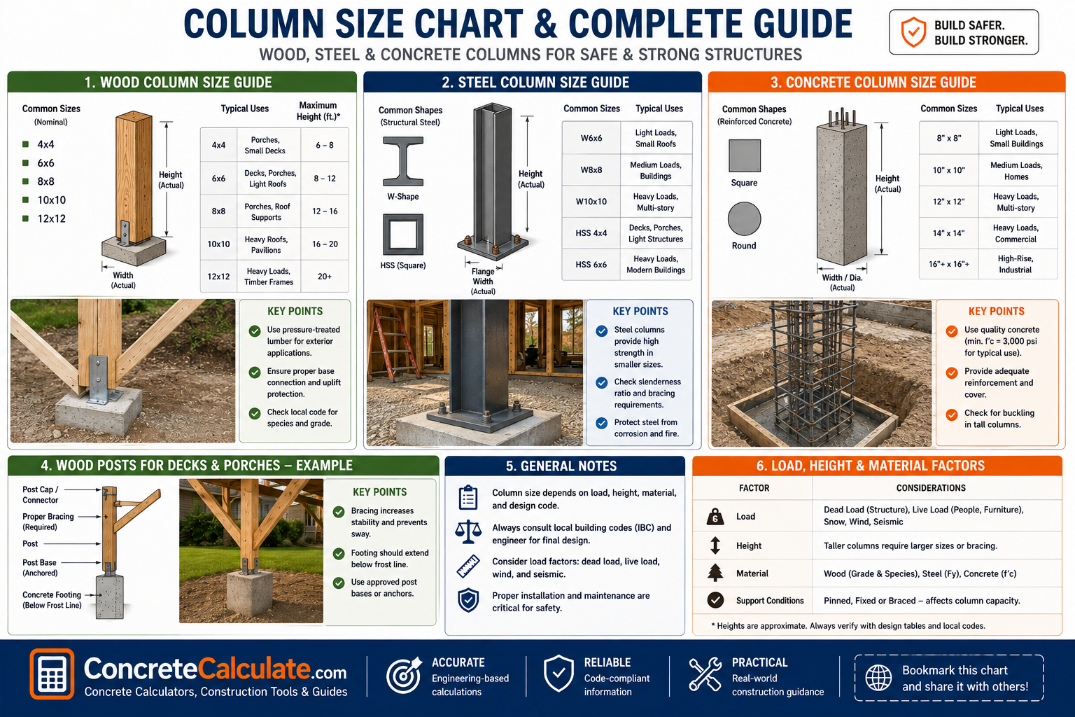
⭐ Column Visual Guide
Original diagrams explaining load path, buckling, tributary area, and section types.
⭐ How to Read a Column Size Chart
Confirm every one of these variables before relying on any numerical column table.
Wood, steel, concrete and composite each use a different design basis.
Match the exact cross-section to the applicable table or product data.
Species/grade for wood, steel grade for steel, and concrete strength/reinforcement for concrete.
This governs slenderness and buckling behavior.
Axial load magnitude, type and any combined bending must be stated.
Braced or unbraced conditions change the effective length used in design.
Verify against the applicable material-specific slenderness limit.
Confirm the section satisfies both pure compression and any combined-load checks.
Base, cap and beam connections must be verified separately from the member.
Footing size and soil bearing capacity complete the load path verification.
How to Choose a Column Size
Complete each step in sequence rather than jumping straight to a cross-section.
Interior, exterior, basement, deck or roof application changes exposure and load type.
Identify the floor or roof area assigned to this column.
Include dead, live, roof, snow and any accumulated multi-floor load.
Measure the actual unsupported length between lateral supports.
Identify braced versus unbraced behavior at each end and along the length.
Select wood, steel, concrete or composite based on application and requirements.
Use a manufacturer table or preliminary chart as a starting point only.
Verify the trial section against the applicable material design method.
Confirm the effective length and slenderness ratio remain within applicable limits.
Account for any eccentricity or applied moment.
Verify base, cap and beam connections for the actual reactions.
Confirm the complete load path down to bearing soil.
⭐ Column Load Worked Examples
These examples demonstrate the selection process. They intentionally stop short of a final engineered size, since that requires project-specific calculation.
1. Basement Wood Post
2. Steel Column
3. Concrete Column
4. Multiple-Floor Column
5. Deck Column
Common Column Sizing Mistakes
A reliable column selection considers the complete structural system, not size or load in isolation.
❌ Sizing from load alone
Height, bracing, material grade and connections all affect actual capacity.
❌ Ignoring column height
Unsupported height directly drives slenderness and buckling behavior.
❌ Ignoring buckling and bracing
A column can fail by buckling before reaching material strength limits.
❌ Ignoring eccentricity
Off-center loads and applied moments reduce pure axial capacity.
❌ Ignoring material grade
Species, grade, steel grade and concrete strength materially change capacity.
❌ Mixing wood and steel capacities
Each material uses a fundamentally different design basis and cannot be substituted.
❌ Using generic steel column loads
Preliminary tables need stated length, grade, and bracing to be meaningful.
❌ Ignoring concrete reinforcement
Reinforcement ratio and detailing are core to concrete column capacity under ACI 318.
❌ Ignoring bearing and connections
Connections must be verified separately from the column member itself.
❌ Ignoring footing capacity
An adequate column does not guarantee an adequate footing or soil bearing condition.
❌ Ignoring wind/seismic effects
Lateral loads can add demand beyond simple gravity load design.
❌ Treating a preliminary chart as final design
Use charts for planning only; obtain a qualified structural design for construction.
Frequently Asked Questions
📄 Download Column Size Chart PDF
Use the print button to create a print-ready or downloadable reference. For structural construction, obtain a project-specific design from a qualified engineer.
Cite or Embed This Chart
Copy the page-wide citation to reference the complete Column Size Chart.