Pipe Flange Size Chart – ASME B16.5 Dimensions and Bolt Patterns
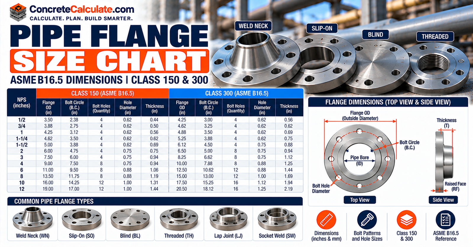
Pipe Flange Size Chart
ASME B16.5 Dimensions and Bolt Patterns
Look up Class 150 and Class 300 flange outside diameter, thickness, bolt circle, hole count and hole size, and learn how NPS, pressure class, flange type, facing and pipe schedule fit together.
 Reviewed by Muhammad Ramzan Babar, PhD Researcher (Plasma Physics) & Calculator Developer – View Profile
Short Answer
Find a flange with three inputs: NPS, pressure class and flange type. NPS is not the flange diameter: an NPS 4 Class 150 flange has a 9.00 in. OD, a 7.50 in. bolt circle and eight 0.75 in. holes, while Class 300 is 10.00 in., 7.88 in. and eight 0.88 in. holes. Class numbers are rating classes, not psi. ASME B16.5 covers NPS 1/2 to 24, and B16.47 covers NPS 26 to 60.
Pipe Flange Size Chart
Use the Class 150 reference below, then confirm class and flange type. A “4-inch flange” is not 4 inches across: NPS 4 Class 150 has a 9.00 in. outside diameter.
How to Read the Chart
Look up the flange with three inputs: NPS, pressure class and flange type. This table is for ASME B16.5 Class 150. Thickness is shown two ways because ASME includes the 1/16 in. raised face in the tabulated minimum thickness for Classes 150 and 300. Class 150 is a rating class, not 150 psi.
Class 150 Quick Reference
| NPS | Flange OD (in.) | Thickness excl. RF (in.) | Min. Thickness incl. RF (in.) | Bolt Circle (in.) | No. of Holes | Hole Dia. (in.) | RF Height (in.) |
|---|---|---|---|---|---|---|---|
| 1/2″ | 3.50 | 0.38 | 0.44 | 2.38 | 4 | 0.62 | 1/16 |
| 3/4″ | 3.88 | 0.44 | 0.50 | 2.75 | 4 | 0.62 | 1/16 |
| 1″ | 4.25 | 0.50 | 0.56 | 3.12 | 4 | 0.62 | 1/16 |
| 1-1/4″ | 4.62 | 0.56 | 0.62 | 3.50 | 4 | 0.62 | 1/16 |
| 2″ | 6.00 | 0.69 | 0.75 | 4.75 | 4 | 0.75 | 1/16 |
| 3″ | 7.50 | 0.88 | 0.94 | 6.00 | 4 | 0.75 | 1/16 |
| 4″ | 9.00 | 0.88 | 0.94 | 7.50 | 8 | 0.75 | 1/16 |
| 6″ | 11.00 | 0.94 | 1.00 | 9.50 | 8 | 0.88 | 1/16 |
| 8″ | 13.50 | 1.06 | 1.12 | 11.75 | 8 | 0.88 | 1/16 |
| 10″ | 16.00 | 1.12 | 1.19 | 14.25 | 12 | 1.00 | 1/16 |
| 12″ | 19.00 | 1.19 | 1.25 | 17.00 | 12 | 1.00 | 1/16 |
| 24″ | 32.00 | 1.81 | 1.88 | 29.50 | 20 | 1.38 | 1/16 |
Dimensions shown are ASME B16.5 Class 150 reference dimensions in inches. Flange type affects bore, hub, length and other geometry. Pressure class is not a direct psi rating. The complete NPS 1/2 to 24 table is in the Class 150 section below.
Reference: ASME B16.5, manufacturer-reproduced dimensions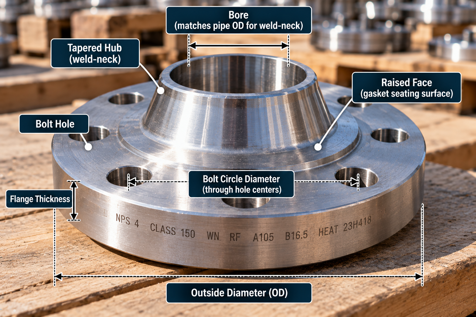
How to Read Pipe Flange Dimensions
| Symbol | Dimension | Meaning |
|---|---|---|
| O | Flange outside diameter | Maximum outside diameter of the flange |
| T | Flange thickness | Flange-body thickness at the specified location |
| BCD | Bolt circle diameter | Diameter of the circle through the bolt-hole centers |
| H | Bolt-hole diameter | Standardized diameter of each bolt hole |
| N | Number of bolt holes | Equally spaced holes around the bolt circle |
| B | Bore | Central opening, which depends on flange type and pipe dimensions |
| RF | Raised-face height | Height of the raised gasket-seating surface, where applicable |
ASME B16.5 Flange Size Range
ASME B16.5-2025 covers pressure-temperature ratings, materials, dimensions, tolerances, marking, testing and the designation of openings for pipe flanges and flanged fittings, NPS 1/2 through NPS 24. It gives requirements in both metric and U.S. customary units, with bolt and bolt-hole diameters expressed in inch units. It also includes requirements and recommendations on flange bolting, gaskets and joints.
| ASME Class | B16.5 Nominal-Size Coverage |
|---|---|
| 150 | NPS 1/2 to 24 |
| 300 | NPS 1/2 to 24 |
| 400 | NPS 1/2 to 24 |
| 600 | NPS 1/2 to 24 |
| 900 | NPS 1/2 to 24 |
| 1500 | NPS 1/2 to 24 |
| 2500 | NPS 1/2 to 12 |
B16.5 is limited to flanges and flanged fittings made from cast or forged materials, plus blind flanges and certain reducing flanges made from cast, forged or plate materials.
Class 150 Flange Size Chart
The table covers every NPS from 1/2 to 24 in. Raised-face height is separate from the flange body.
| NPS | O (in.) | T excl. RF (in.) | Min. T incl. RF (in.) | Bolt Circle (in.) | Holes x Dia. (in.) | RF Height (in.) |
|---|---|---|---|---|---|---|
| 1/2″ | 3.50 | 0.38 | 0.44 | 2.38 | 4 x 0.62 | 1/16 |
| 3/4″ | 3.88 | 0.44 | 0.50 | 2.75 | 4 x 0.62 | 1/16 |
| 1″ | 4.25 | 0.50 | 0.56 | 3.12 | 4 x 0.62 | 1/16 |
| 1-1/4″ | 4.62 | 0.56 | 0.62 | 3.50 | 4 x 0.62 | 1/16 |
| 1-1/2″ | 5.00 | 0.62 | 0.69 | 3.88 | 4 x 0.62 | 1/16 |
| 2″ | 6.00 | 0.69 | 0.75 | 4.75 | 4 x 0.75 | 1/16 |
| 2-1/2″ | 7.00 | 0.81 | 0.88 | 5.50 | 4 x 0.75 | 1/16 |
| 3″ | 7.50 | 0.88 | 0.94 | 6.00 | 4 x 0.75 | 1/16 |
| 3-1/2″ | 8.50 | 0.88 | 0.94 | 7.00 | 8 x 0.75 | 1/16 |
| 4″ | 9.00 | 0.88 | 0.94 | 7.50 | 8 x 0.75 | 1/16 |
| 5″ | 10.00 | 0.88 | 0.94 | 8.50 | 8 x 0.88 | 1/16 |
| 6″ | 11.00 | 0.94 | 1.00 | 9.50 | 8 x 0.88 | 1/16 |
| 8″ | 13.50 | 1.06 | 1.12 | 11.75 | 8 x 0.88 | 1/16 |
| 10″ | 16.00 | 1.12 | 1.19 | 14.25 | 12 x 1.00 | 1/16 |
| 12″ | 19.00 | 1.19 | 1.25 | 17.00 | 12 x 1.00 | 1/16 |
| 14″ | 21.00 | 1.31 | 1.38 | 18.75 | 12 x 1.12 | 1/16 |
| 16″ | 23.50 | 1.38 | 1.44 | 21.25 | 16 x 1.12 | 1/16 |
| 18″ | 25.00 | 1.50 | 1.56 | 22.75 | 16 x 1.25 | 1/16 |
| 20″ | 27.50 | 1.62 | 1.69 | 25.00 | 20 x 1.25 | 1/16 |
| 22″ | 29.50 | 1.75 | 1.81 | 27.25 | 20 x 1.38 | 1/16 |
| 24″ | 32.00 | 1.81 | 1.88 | 29.50 | 20 x 1.38 | 1/16 |
Class 300 Flange Size Chart
Class 300 dimensions are not obtained by multiplying Class 150 dimensions. Compare NPS 4: Class 150 has a 9.00 in. OD, 7.50 in. bolt circle and 0.75 in. holes, while Class 300 has a 10.00 in. OD, 7.88 in. bolt circle and 0.88 in. holes.
| NPS | O (in.) | T excl. RF (in.) | Min. T incl. RF (in.) | Bolt Circle (in.) | Holes x Dia. (in.) | RF Height (in.) |
|---|---|---|---|---|---|---|
| 1/2″ | 3.75 | 0.50 | 0.56 | 2.62 | 4 x 0.63 | 1/16 |
| 3/4″ | 4.62 | 0.56 | 0.62 | 3.25 | 4 x 0.75 | 1/16 |
| 1″ | 4.88 | 0.62 | 0.69 | 3.50 | 4 x 0.75 | 1/16 |
| 1-1/4″ | 5.25 | 0.69 | 0.75 | 3.88 | 4 x 0.75 | 1/16 |
| 1-1/2″ | 6.12 | 0.75 | 0.81 | 4.50 | 4 x 0.88 | 1/16 |
| 2″ | 6.50 | 0.81 | 0.88 | 5.00 | 8 x 0.75 | 1/16 |
| 2-1/2″ | 7.50 | 0.94 | 1.00 | 5.88 | 8 x 0.88 | 1/16 |
| 3″ | 8.25 | 1.06 | 1.12 | 6.62 | 8 x 0.88 | 1/16 |
| 3-1/2″ | 9.00 | 1.12 | 1.19 | 7.25 | 8 x 0.88 | 1/16 |
| 4″ | 10.00 | 1.19 | 1.25 | 7.88 | 8 x 0.88 | 1/16 |
| 5″ | 11.00 | 1.31 | 1.38 | 9.25 | 8 x 0.88 | 1/16 |
| 6″ | 12.50 | 1.38 | 1.44 | 10.62 | 12 x 0.88 | 1/16 |
| 8″ | 15.00 | 1.56 | 1.62 | 13.00 | 12 x 1.00 | 1/16 |
| 10″ | 17.50 | 1.81 | 1.88 | 15.25 | 16 x 1.12 | 1/16 |
| 12″ | 20.50 | 1.94 | 2.00 | 17.75 | 16 x 1.25 | 1/16 |
| 14″ | 23.00 | 2.06 | 2.12 | 20.25 | 20 x 1.25 | 1/16 |
| 16″ | 25.50 | 2.19 | 2.25 | 22.50 | 20 x 1.38 | 1/16 |
| 18″ | 28.00 | 2.31 | 2.38 | 24.75 | 24 x 1.38 | 1/16 |
| 20″ | 30.50 | 2.44 | 2.50 | 27.00 | 24 x 1.38 | 1/16 |
| 22″ | 33.00 | 2.57 | 2.63 | 29.25 | 24 x 1.63 | 1/16 |
| 24″ | 36.00 | 2.69 | 2.75 | 32.00 | 24 x 1.63 | 1/16 |
Class 150 vs. Class 300 for NPS 4
| Dimension | Class 150 | Class 300 |
|---|---|---|
| Flange OD | 9.00 in. | 10.00 in. |
| Bolt circle | 7.50 in. | 7.88 in. |
| Number of holes | 8 | 8 |
| Hole diameter | 0.75 in. | 0.88 in. |
| Thickness excl. RF | 0.88 in. | 1.19 in. |
| Min. thickness incl. RF | 0.94 in. | 1.25 in. |
Classes 400, 600, 900, 1500 and 2500
Dimensions become class-specific from Class 400 up. Thickness generally increases, bolting changes, and the OD and bolt pattern may change. Class 2500 stops at NPS 12 under B16.5. This page does not republish those tables, because missing values should come from the standard and not from guesses.
| Class | B16.5 Coverage | Raised-Face Height |
|---|---|---|
| 400 | NPS 1/2 to 24 | 1/4 in. |
| 600 | NPS 1/2 to 24 | 1/4 in. |
| 900 | NPS 1/2 to 24 | 1/4 in. |
| 1500 | NPS 1/2 to 24 | 1/4 in. |
| 2500 | NPS 1/2 to 12 | 1/4 in. |
For the higher classes, ASME convention is to list thickness without the 1/4 in. raised face, unlike Classes 150 and 300, which include 1/16 in. Always read the source table legend.
What Does Flange Class Mean?
Class 150 does not mean 150 psi. The class is a rating designation, and the allowable pressure depends on the material group and the temperature. As an illustration, a Class 150 flange in A105 carbon steel (Material Group 1.1) is rated 285 psig from -20°F to 100°F, and the rating falls as temperature rises.
| Class and Material | At 100°F or Below | At 500°F |
|---|---|---|
| Class 150 (A105, Group 1.1) | 285 psig | about 170 psig |
| Class 300 (A105, Group 1.1) | 740 psig | 605 psig |
| Class 600 (A105, Group 1.1) | 1480 psig | not shown |
Nominal Pipe Size vs. Flange Outside Diameter
NPS identifies the connected piping size and not the physical flange diameter. For NPS 4 Class 150, the flange OD is 9.00 in. The nominal size of 4 is a designation, and the pipe itself measures 4.500 in. across. Complete NPS-to-OD data is in the Pipe Outside Diameter Chart.
Pipe OD vs. Flange Bore
For NPS 4 steel pipe the OD is 4.500 in. for every common schedule. Wall thickness changes the ID. The weld-neck bore must match the pipe bore, while the flange OD and bolt pattern stay the same.
| Pipe Schedule | Wall (in.) | Pipe ID (in.) |
|---|---|---|
| Schedule 40 | 0.237 | 4.026 |
| Schedule 80 | 0.337 | 3.826 |
The Texas Flange table lists a standard weld-neck bore of 4.03 in. for NPS 4, which corresponds to standard-wall pipe. Wall thickness and ID are in the Pipe Wall Thickness Chart and the Pipe Inside Diameter Chart.
Does Pipe Schedule Change Flange Size?
Flange OD and bolt pattern are determined mainly by NPS, flange class and the applicable standard, not by pipe schedule. A weld-neck flange is different: its bore is machined to suit the pipe wall, so Schedule 40 and Schedule 80 pipe of the same NPS and class share the same bolt-pattern envelope but need different weld-neck bore details. Do not describe schedule as irrelevant to flange selection. The Pipe Schedule Chart explains the schedule system.
Flange Bolt Circle Diameter Chart
For NPS 4 Class 150, BCD = 7.50 in., so R = 3.75 in. This is useful for layout and inspection, but it does not replace the standard.
| NPS | Class 150 BCD (in.) | Class 150 Radius (in.) | Class 300 BCD (in.) | Class 300 Radius (in.) |
|---|---|---|---|---|
| 1/2″ | 2.38 | 1.190 | 2.62 | 1.310 |
| 3/4″ | 2.75 | 1.375 | 3.25 | 1.625 |
| 1″ | 3.12 | 1.560 | 3.50 | 1.750 |
| 1-1/4″ | 3.50 | 1.750 | 3.88 | 1.940 |
| 1-1/2″ | 3.88 | 1.940 | 4.50 | 2.250 |
| 2″ | 4.75 | 2.375 | 5.00 | 2.500 |
| 2-1/2″ | 5.50 | 2.750 | 5.88 | 2.940 |
| 3″ | 6.00 | 3.000 | 6.62 | 3.310 |
| 3-1/2″ | 7.00 | 3.500 | 7.25 | 3.625 |
| 4″ | 7.50 | 3.750 | 7.88 | 3.940 |
| 5″ | 8.50 | 4.250 | 9.25 | 4.625 |
| 6″ | 9.50 | 4.750 | 10.62 | 5.310 |
| 8″ | 11.75 | 5.875 | 13.00 | 6.500 |
| 10″ | 14.25 | 7.125 | 15.25 | 7.625 |
| 12″ | 17.00 | 8.500 | 17.75 | 8.875 |
| 14″ | 18.75 | 9.375 | 20.25 | 10.125 |
| 16″ | 21.25 | 10.625 | 22.50 | 11.250 |
| 18″ | 22.75 | 11.375 | 24.75 | 12.375 |
| 20″ | 25.00 | 12.500 | 27.00 | 13.500 |
| 22″ | 27.25 | 13.625 | 29.25 | 14.625 |
| 24″ | 29.50 | 14.750 | 32.00 | 16.000 |
Flange Bolt Hole Size and Number
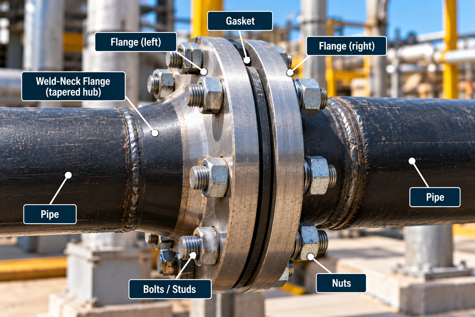
Number of holes and hole diameter are fixed by NPS and class. NPS 4 Class 150 has 8 holes of 0.75 in. on a 7.50 in. bolt circle. The Texas Flange table notes that the hole is 1/8 in. larger than the bolt, so the bolt diameters below are derived from the hole size. Flange holes are standard-specific, not ordinary clearance holes. For general references see the Bolt Hole Size Chart, the Hex Bolt Size Chart, the Nut Size Chart and the Washer Size Chart.
| NPS | Class 150: Holes x Dia. | Class 150 Bolt (derived) | Class 300: Holes x Dia. | Class 300 Bolt (derived) |
|---|---|---|---|---|
| 1/2″ | 4 x 0.62 | 1/2″ | 4 x 0.63 | 1/2″ |
| 1″ | 4 x 0.62 | 1/2″ | 4 x 0.75 | 5/8″ |
| 2″ | 4 x 0.75 | 5/8″ | 8 x 0.75 | 5/8″ |
| 4″ | 8 x 0.75 | 5/8″ | 8 x 0.88 | 3/4″ |
| 6″ | 8 x 0.88 | 3/4″ | 12 x 0.88 | 3/4″ |
| 8″ | 8 x 0.88 | 3/4″ | 12 x 1.00 | 7/8″ |
| 12″ | 12 x 1.00 | 7/8″ | 16 x 1.25 | 1-1/8″ |
| 24″ | 20 x 1.38 | 1-1/4″ | 24 x 1.63 | 1-1/2″ |
Weld-Neck Flange Dimensions
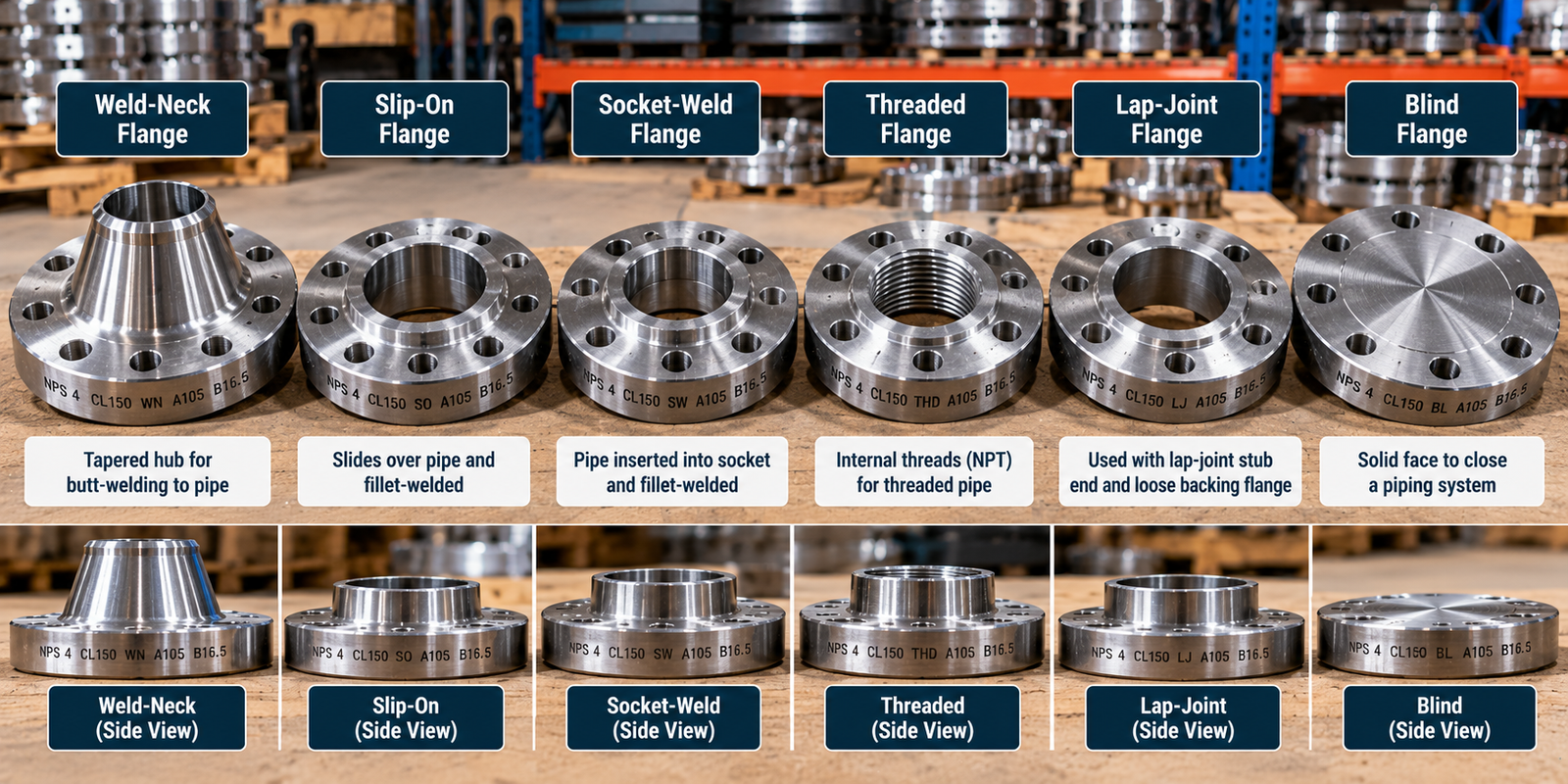
A weld-neck flange has a long tapered hub that is butt-welded to the pipe. Its important dimensions are the bore, hub diameter, overall length, flange OD and thickness. Match the bore to the pipe wall and schedule. Because hub and length dimensions are type-specific, read them from the weld-neck column of the standard or the manufacturer table.
| Flange Type | Connection | Important Sizing Feature | Typical Role |
|---|---|---|---|
| Weld neck | Butt welded | Hub and bore | Higher-integrity piping |
| Slip-on | Slides over pipe and fillet welds | Bore | General welded piping |
| Socket weld | Pipe inserted into a socket | Socket and bore dimensions | Smaller-size piping |
| Threaded | Internal pipe thread | Threaded bore | No butt weld required |
| Lap joint | Used with a stub end | Loose rotating flange | Alignment and disassembly |
| Blind | No bore | Solid center | Closing a pipe or flanged opening |
Slip-On Flange Dimensions
The pipe passes into the slip-on flange bore, and the flange is fillet-welded. Its bore and hub geometry differ from a weld-neck flange, so the same NPS and class do not mean every dimension equals a weld-neck flange.
Socket-Weld and Threaded Flanges
Socket-Weld Flange
The pipe is inserted into a socket, so the socket and bore dimensions govern.
Threaded Flange
A threaded bore connects the pipe with no butt weld. Check the thread requirements. Neither type is a weld-neck flange without the neck.
Lap-Joint Flange Dimensions
A lap-joint flange is used with a stub end and can rotate around it, which helps with bolt-hole alignment. Its bore and hub geometry are different from other types. Stub-end dimensions are outside this page.
Blind Flange Size Chart
A blind flange has no through bore and closes a flanged opening. Its OD and bolt pattern match the mating flanges for the same NPS and class, as shown below. Its thickness follows the separate blind-flange table in the standard and should not be assumed equal to the weld-neck or slip-on thickness, so thickness values are not republished here. Blind flanges also get substantially heavier at larger sizes.
| NPS | Class 150 OD (in.) | Class 150 BCD (in.) | Class 150 Holes | Class 300 OD (in.) | Class 300 BCD (in.) | Class 300 Holes |
|---|---|---|---|---|---|---|
| 2″ | 6.00 | 4.75 | 4 x 0.75 | 6.50 | 5.00 | 8 x 0.75 |
| 4″ | 9.00 | 7.50 | 8 x 0.75 | 10.00 | 7.88 | 8 x 0.88 |
| 6″ | 11.00 | 9.50 | 8 x 0.88 | 12.50 | 10.62 | 12 x 0.88 |
| 8″ | 13.50 | 11.75 | 8 x 0.88 | 15.00 | 13.00 | 12 x 1.00 |
| 12″ | 19.00 | 17.00 | 12 x 1.00 | 20.50 | 17.75 | 16 x 1.25 |
| 24″ | 32.00 | 29.50 | 20 x 1.38 | 36.00 | 32.00 | 24 x 1.63 |
Raised-Face vs. Flat-Face Flanges
Raised Face (RF)
The gasket contact area is raised above the main flange face. In ASME B16.5 it is about 1/16 in. (1.6 mm) for Classes 150 and 300, and about 1/4 in. (6.4 mm) for Classes 400 through 2500.
Flat Face (FF)
The gasket surface lies in the same plane as the flange face.
RF and FF flanges are not interchangeable in every joint. Do not confuse raised-face height with flange thickness: for Classes 150 and 300 the tabulated minimum thickness includes the 1/16 in. raised face.
Ring-Type Joint Flanges
A ring-type joint (RTJ) flange has a machined ring groove and uses a metallic ring gasket in higher-pressure or specified services. Groove and ring dimensions are standard-specific, and ASME B16.20 covers metal ring-joint gaskets. A complete RTJ groove table is not reproduced here.
Flange Gasket Size and Compatibility
Gasket selection depends on NPS, class, facing, gasket type, material and service. ASME B16.20-2023 covers metallic gaskets (ring-joint, spiral-wound and metal-jacketed) and ASME B16.21-2021 covers nonmetallic flat gaskets, both dimensionally suitable for the referenced flange standards. This page gives context and not a gasket size chart. After assembly, tightening follows the project procedure; the Bolt Torque Chart is a general fastener reference and not a flange procedure.
Large-Diameter Pipe Flanges: ASME B16.47
ASME B16.47-2025 covers large-diameter steel flanges NPS 26 through 60 in Classes 75, 150, 300, 400, 600 and 900. B16.5 covers NPS 1/2 through 24, so do not extend a B16.5 chart beyond NPS 24.
NPS 26-60
B16.47 contains blind and weld-neck flanges for these sizes.
Series A vs. Series B
B16.47 has two flange systems, Series A and Series B, with different OD, bolt circle and bolt count at every size. They do not bolt together, so do not combine them in one table. As one Series A example, an NPS 26 Class 150 flange has a 34.25 in. OD, a 31.75 in. bolt circle, 24 bolts and 1-1/4 in. studs.
Inch vs. Metric Flange Dimensions
For the NPS 4 Class 150 OD: 9.00 × 25.4 = 228.6 mm. B16.5 gives both U.S. customary and metric requirements, with bolt and hole diameters in inches. Converting an ASME flange to millimeters does not make it equivalent to an EN or DIN PN flange.
| NPS | OD (in.) | OD (mm) | Bolt Circle (in.) | Bolt Circle (mm) | Hole Dia. (mm) |
|---|---|---|---|---|---|
| 2″ | 6.00 | 152.4 | 4.75 | 120.6 | 19.0 |
| 4″ | 9.00 | 228.6 | 7.50 | 190.5 | 19.0 |
| 6″ | 11.00 | 279.4 | 9.50 | 241.3 | 22.4 |
| 8″ | 13.50 | 342.9 | 11.75 | 298.4 | 22.4 |
How to Identify and Select a Pipe Flange
- Identify NPS.
- Identify the applicable standard (B16.5 up to NPS 24, B16.47 above).
- Identify the pressure class.
- Identify the flange type.
- Identify the facing.
- Identify the material.
- Determine pipe OD and schedule where relevant.
- Verify the flange bore and hub.
- Verify the bolt pattern.
- Select compatible gasket and bolting.
- Check the pressure-temperature rating.
- Verify the project specification and code.
Flange Dimension Lookup
The lookup covers only the Class 150 and 300 reference tables on this page. Confirm against ASME B16.5 and the project specification.
Common Pipe Flange Sizing Mistakes
Assuming NPS equals flange OD
NPS 4 Class 150 is 9.00 in. across.
Calling Class 150 150 psi
It is a rating class.
Ignoring pressure class
Dimensions change with class.
Mixing Class 150 and Class 300 dimensions
Bolt patterns do not interchange.
Assuming all flange types have identical dimensions
Bore, hub and length differ.
Ignoring pipe schedule for weld-neck bore
The bore matches the pipe wall.
Extending B16.5 above NPS 24
Use B16.47 for NPS 26 to 60.
Mixing B16.47 Series A and B
They do not bolt together.
Treating bolt-hole diameter as bolt diameter
The hole is 1/8 in. larger here.
Confusing raised-face height with flange thickness
They are different values.
Mixing ASME Class with European PN
Different systems.
Choosing a gasket from pipe diameter alone
Class, facing and type matter.
Assuming any two same-NPS flanges will bolt together
Class and standard must match.
Limitations
What This Chart Does Not Establish
This page is a general flange dimensional reference built on ASME B16.5 Class 150 and Class 300 values reproduced from a manufacturer. It does not establish pressure-temperature ratings for your material, blind-flange thickness, hub and bore dimensions, Class 400 and higher dimensions, gasket or ring-groove dimensions, or compliance with any project. Verify against the current edition of ASME B16.5 and the project specification. See the Construction Charts hub for related references.
Pipe Flange Size FAQs
What are standard pipe flange sizes?
How is pipe flange size measured?
What size is a 4-inch flange?
Is a 4-inch flange actually 4 inches in diameter?
What is Class 150 flange size?
Does Class 150 mean 150 psi?
What is flange bolt-circle diameter?
How many bolt holes does a 4-inch Class 150 flange have?
Does pipe schedule change flange dimensions?
What is the difference between Class 150 and Class 300?
What is the difference between weld-neck and slip-on flanges?
What is RF vs. FF?
What standard covers pipe flanges?
What standard covers flanges larger than 24 inches?
What is B16.47 Series A vs. Series B?
Save the Pipe Flange Size Chart as a PDF
Use your browser print function to save this reference for the shop, estimating folders and piping take-offs.