
Cast Iron Pipe Size Chart – No-Hub, Service & Extra Heavy
Cast Iron Pipe Size ChartNo-Hub, Service & Extra Heavy
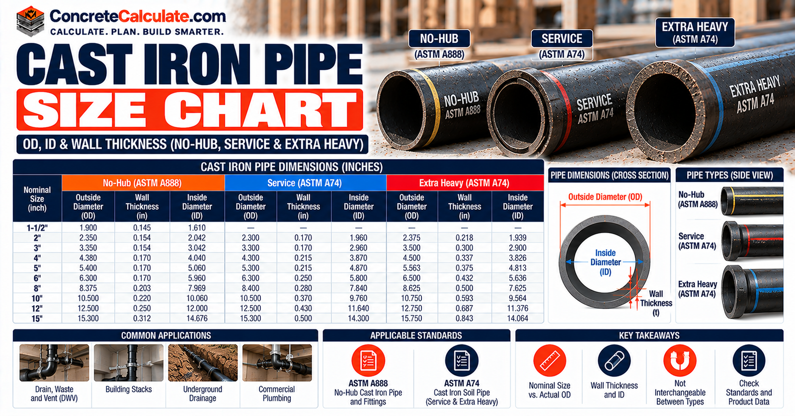
Nominal and actual barrel outside diameters, wall thickness and inside diameters for cast iron soil pipe, with the differences between hubless and hub-and-spigot pipe.
 Reviewed by Muhammad Ramzan Babar, PhD Researcher (Plasma Physics) & Calculator Developer | View Profile
Quick Answer: Cast Iron Soil Pipe Has Three Size Systems
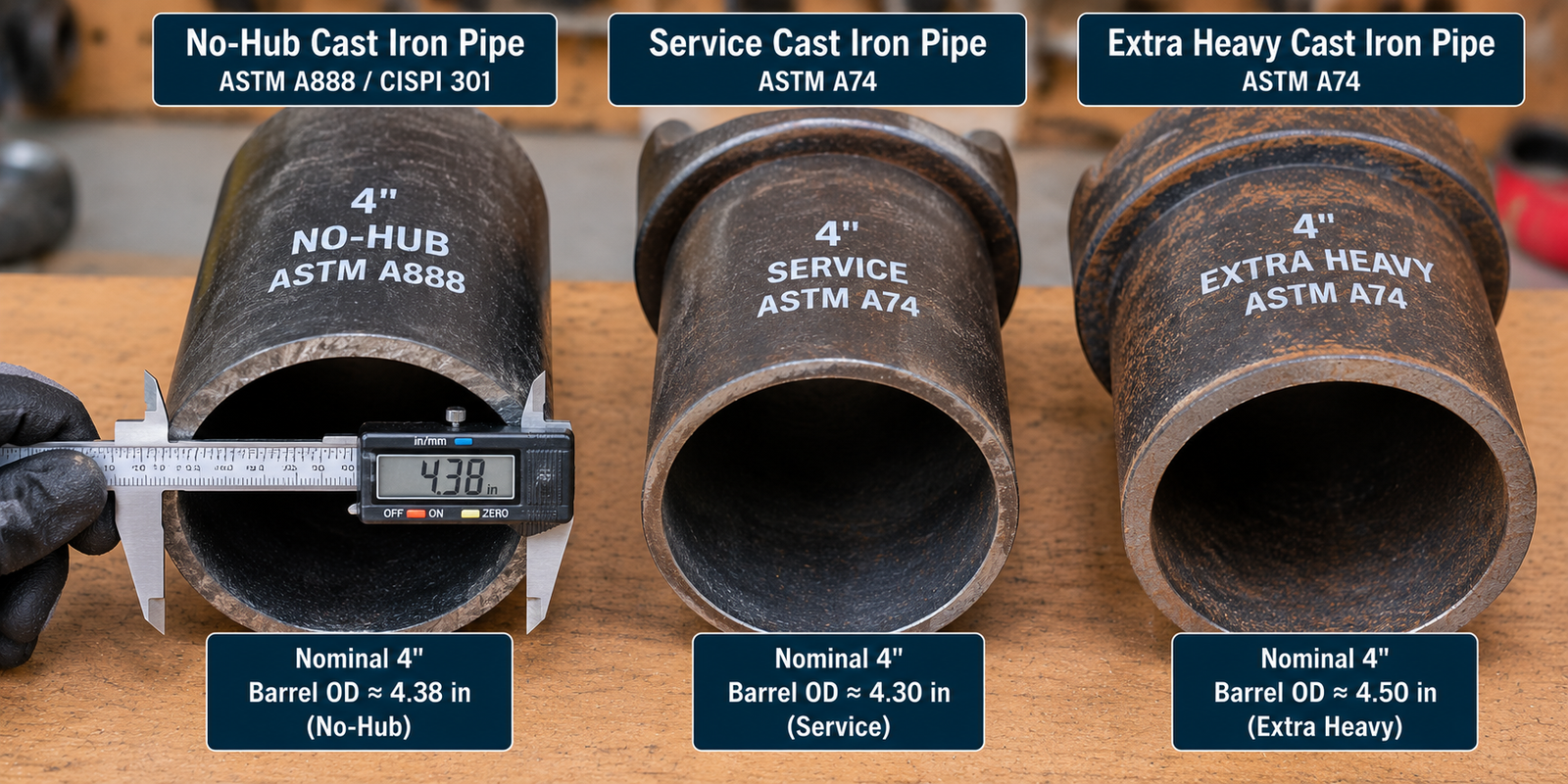
- Nominal 4-inch barrel OD: 4.38 in No-Hub, 4.30 in Service (SV), 4.50 in Extra Heavy (XH).
- No-Hub pipe follows ASTM A888 and CISPI 301. Service and Extra Heavy hub-and-spigot pipe follow ASTM A74.
- This is non-pressure drain, waste and vent pipe. A nominal size alone cannot tell you the OD or the right coupling.
Cast Iron Pipe Size Chart
No-Hub, Service and Extra Heavy outside diameters side by side.
Identify the pipe type first: No-Hub, Service or Extra Heavy. The chart shows nominal barrel outside diameters, not hub diameters or fitting dimensions.
| Nominal pipe size | No-Hub OD (in) | Service (SV) OD (in) | Extra Heavy (XH) OD (in) |
|---|---|---|---|
| 1-1/2″ | 1.90 | – | – |
| 2″ | 2.35 | 2.30 | 2.38 |
| 3″ | 3.35 | 3.30 | 3.50 |
| 4″ | 4.38 | 4.30 | 4.50 |
| 5″ | 5.30 | 5.30 | 5.50 |
| 6″ | 6.30 | 6.30 | 6.50 |
| 8″ | 8.38 | 8.38 | 8.62 |
| 10″ | 10.56 | 10.50 | 10.75 |
| 12″ | 12.50 | 12.50 | 12.75 |
| 15″ | 15.83 | 15.88 | 15.88 |
Nominal pipe barrel OD in inches. A dash means the reference lists no value for that size and type; it does not prove the size is unavailable. Governing standards: No-Hub, ASTM A888 / CISPI 301; Service and Extra Heavy, ASTM A74.
How to read this chart
Find your nominal size, then read across to the OD for your pipe type. Values are nominal and subject to the standard’s tolerances. They are not pressure ratings and not hub or fitting dimensions.
Data basis
Nominal ODs are consistent with the Cast Iron Soil Pipe Institute handbook and Charlotte Pipe’s 2026 dimensional data. The No-Hub 15-inch OD is 15.83 in in that current manufacturer data; some older tables show 15.88 in, which is the Service and Extra Heavy value.
How to Read Cast Iron Pipe Dimensions
Nominal size, OD, ID, wall, hub and tolerance explained.
Six terms appear in cast iron pipe data. Keep them separate.
Nominal size
The trade size, such as 2, 3, 4 or 6 in. It is not the measured diameter.
Outside diameter
The barrel OD. It differs by pipe type for the same nominal size.
Inside diameter
The barrel bore. It is tabulated with a tolerance or calculated from OD and wall.
Wall thickness
Nominal wall is a design value. Minimum and actual measured walls can differ.
Hub and spigot
The hub is the enlarged socket end. Hub dimensions are separate from barrel OD.
Tolerance
Field measurements can differ from tabulated nominals, so read the tolerance.
For comparisons across materials, see the Pipe Outside Diameter Chart.
Figure 1. Cast iron soil pipe barrel cross-section, schematic and not to scale.
No-Hub Cast Iron Pipe Size Chart
Hubless pipe under ASTM A888 and CISPI 301.
No-Hub pipe has plain ends on both sides. It is joined with a compatible shielded hubless coupling and covered by ASTM A888 and CISPI 301.
| Nominal size | Barrel OD (in) | OD tolerance (in) | OD (mm) | Barrel ID (in) | ID tolerance (in) | Nominal wall (in) | Min. wall (in) |
|---|---|---|---|---|---|---|---|
| 1-1/2″ | 1.90 | ±0.06 | 48.3 | 1.50 | ±0.09 | 0.16 | 0.13 |
| 2″ | 2.35 | ±0.09 | 59.7 | 1.96 | ±0.09 | 0.16 | 0.13 |
| 3″ | 3.35 | ±0.09 | 85.1 | 2.96 | ±0.09 | 0.16 | 0.13 |
| 4″ | 4.38 | +0.09 / -0.05 | 111.3 | 3.94 | ±0.09 | 0.19 | 0.15 |
| 5″ | 5.30 | +0.09 / -0.05 | 134.6 | 4.94 | ±0.09 | 0.19 | 0.15 |
| 6″ | 6.30 | +0.09 / -0.05 | 160.0 | 5.94 | ±0.09 | 0.19 | 0.15 |
| 8″ | 8.38 | ±0.09 | 212.9 | 7.94 | ±0.13 | 0.23 | 0.17 |
| 10″ | 10.56 | ±0.09 | 268.2 | 10.00 | ±0.13 | 0.28 | 0.22 |
| 12″ | 12.50 | ±0.13 | 317.5 | 11.94 | ±0.09 | 0.28 | 0.22 |
| 15″ | 15.83 | ±0.13 | 402.1 | 15.11 | ±0.09 | 0.36 | 0.30 |
Dimensions are the manufacturer’s published nominal values with tolerances; tolerances for OD and ID are shown as published. Charlotte Pipe lists No-Hub pipe from 1-1/2 to 15 in.
Do not use these dimensions for Service or Extra Heavy pipe, even though all three are cast iron DWV products.
Service Cast Iron Pipe Size Chart
Service-weight hub-and-spigot pipe under ASTM A74.
Service (SV) pipe is hub-and-spigot pipe under ASTM A74. The barrel OD is smaller than the hub, so measure the barrel and not the hub.
| Nominal size | Barrel OD (in) | OD (mm) | Barrel ID (in) | Nominal wall (in) |
|---|---|---|---|---|
| 2″ | 2.30 | 58.4 | 1.96 | 0.17 |
| 3″ | 3.30 | 83.8 | 2.96 | 0.17 |
| 4″ | 4.30 | 109.2 | 3.94 | 0.18 |
| 5″ | 5.30 | 134.6 | 4.94 | 0.18 |
| 6″ | 6.30 | 160.0 | 5.94 | 0.18 |
| 8″ | 8.38 | 212.9 | 7.94 | 0.23 |
| 10″ | 10.50 | 266.7 | 9.94 | 0.28 |
| 12″ | 12.50 | 317.5 | 11.94 | 0.28 |
| 15″ | 15.88 | 403.4 | 15.16 | 0.36 |
Barrel dimensions only. Hub dimensions are in the hub-and-spigot section below. Do not apply No-Hub dimensions to Service pipe.
Extra Heavy Cast Iron Pipe Size Chart
Extra Heavy hub-and-spigot pipe under ASTM A74.
Extra Heavy (XH) pipe also follows ASTM A74. Its extra wall is added outward, so the barrel OD is larger than Service at the same nominal size.
| Nominal size | Barrel OD (in) | OD (mm) | Barrel ID (in) | Nominal wall (in) |
|---|---|---|---|---|
| 2″ | 2.38 | 60.5 | 2.00 | 0.19 |
| 3″ | 3.50 | 88.9 | 3.00 | 0.25 |
| 4″ | 4.50 | 114.3 | 4.00 | 0.25 |
| 5″ | 5.50 | 139.7 | 5.00 | 0.25 |
| 6″ | 6.50 | 165.1 | 6.00 | 0.25 |
| 8″ | 8.62 | 218.9 | 8.00 | 0.31 |
| 10″ | 10.75 | 273.1 | 10.00 | 0.37 |
| 12″ | 12.75 | 323.9 | 12.00 | 0.37 |
| 15″ | 15.88 | 403.4 | 15.00 | 0.44 |
The OD difference between Service and Extra Heavy is not the same for every size. At 2 in it is 0.08 in, at 3 to 6 in it is 0.20 in, at 8 to 12 in it is 0.24 to 0.25 in, and at 15 in the ODs match.
No-Hub vs. Service vs. Extra Heavy Cast Iron
The central distinction for identifying and replacing pipe.
| Feature | No-Hub | Service (SV) | Extra Heavy (XH) |
|---|---|---|---|
| Joint type | Plain ends, shielded coupling | Hub and spigot, compression gasket | Hub and spigot, compression gasket |
| Standard | ASTM A888 / CISPI 301 | ASTM A74 | ASTM A74 |
| 4 in barrel OD | 4.38 in | 4.30 in | 4.50 in |
| 4 in nominal wall | 0.19 in | 0.18 in | 0.25 in |
| Replacement parts | Hubless couplings and fittings | SV gaskets and fittings | XH gaskets and fittings |
| Identification | No hub on the pipe | Hub on one end; check OD and markings | Hub on one end; check OD and markings |
| Pipe type | Nominal size | Nominal barrel OD |
|---|---|---|
| No-Hub | 4″ | 4.38 in |
| Service | 4″ | 4.30 in |
| Extra Heavy | 4″ | 4.50 in |
The 0.20 in difference between 4-inch Service (4.30 in) and Extra Heavy (4.50 in) is large enough to change coupling and gasket selection. Gaskets sized for one are not interchangeable with the other.
Figure 2. Nominal 4-inch No-Hub, Service and Extra Heavy cast iron pipe at equal scale.
Cast Iron Pipe Wall Thickness Chart
Nominal wall by pipe type, and what that number means.
Wall thickness is where Service and Extra Heavy really differ. Extra Heavy adds wall outward, which raises the OD.
| Nominal size | No-Hub nominal wall | No-Hub minimum wall | Service nominal wall | Extra Heavy nominal wall |
|---|---|---|---|---|
| 1-1/2″ | 0.16 | 0.13 | – | – |
| 2″ | 0.16 | 0.13 | 0.17 | 0.19 |
| 3″ | 0.16 | 0.13 | 0.17 | 0.25 |
| 4″ | 0.19 | 0.15 | 0.18 | 0.25 |
| 5″ | 0.19 | 0.15 | 0.18 | 0.25 |
| 6″ | 0.19 | 0.15 | 0.18 | 0.25 |
| 8″ | 0.23 | 0.17 | 0.23 | 0.31 |
| 10″ | 0.28 | 0.22 | 0.28 | 0.37 |
| 12″ | 0.28 | 0.22 | 0.28 | 0.37 |
| 15″ | 0.36 | 0.30 | 0.36 | 0.44 |
- Nominal wall is a design value, not an acceptance limit.
- Minimum wall is published for No-Hub pipe in this data; the A74 acceptance limits are in the standard.
- Manufacturing tolerance and wall loss in old pipe change the real wall.
For other wall systems, see the Pipe Wall Thickness Chart.
Cast Iron Pipe Inside Diameter Chart
ID formula, calculated versus published values, and a worked example.
Different pipe types have different ODs but similar nominal openings. Calculated ID uses nominal OD and nominal wall, and published ID is the manufacturer’s tabulated value.
Inside diameter formula
- OD = nominal barrel outside diameter (in)
- t = nominal wall thickness (in)
- ID = calculated inside diameter (in)
| Nominal size and type | Nominal OD (in) | Nominal wall (in) | Calculated ID (in) | Published ID (in) |
|---|---|---|---|---|
| 2″ No-Hub | 2.35 | 0.16 | 2.03 | 1.96 ±0.09 |
| 2″ Service | 2.30 | 0.17 | 1.96 | 1.96 |
| 2″ Extra Heavy | 2.38 | 0.19 | 2.00 | 2.00 |
| 4″ No-Hub | 4.38 | 0.19 | 4.00 | 3.94 ±0.09 |
| 4″ Service | 4.30 | 0.18 | 3.94 | 3.94 |
| 4″ Extra Heavy | 4.50 | 0.25 | 4.00 | 4.00 |
Calculated values are approximate geometric IDs, not guaranteed minimum or maximum bores. Published No-Hub IDs differ slightly from the calculation because OD, wall and ID are separately toleranced.
4-Inch No-Hub Calculated ID
What it means: The published barrel ID is 3.94 in with a tolerance of 0.09 in, so 4.00 in is inside that range. Use the published value or measure when it matters, and treat corrosion or buildup as reducing the real opening.
For other ID references, see the Pipe Inside Diameter Chart.
Common Cast Iron Pipe Sizes
2, 3, 4, 6 and larger sizes at a glance.
Quick reference for common sizes. Fixture sizing and capacity come from the plumbing code, not from this chart.
2-Inch Cast Iron
No-Hub 2.35 in
Service 2.30 in; Extra Heavy 2.38 in barrel OD.
Nominal wall: 0.16 / 0.17 / 0.19 in (No-Hub / Service / Extra Heavy).
Match a 2-inch coupling or gasket to the actual pipe type, because the three ODs are 2.35, 2.30 and 2.38 in.
3-Inch Cast Iron
No-Hub 3.35 in
Service 3.30 in; Extra Heavy 3.50 in barrel OD.
Nominal wall: 0.16 / 0.17 / 0.25 in (No-Hub / Service / Extra Heavy).
The same nominal 3-inch designation covers ODs of 3.35, 3.30 and 3.50 in.
4-Inch Cast Iron
No-Hub 4.38 in
Service 4.30 in; Extra Heavy 4.50 in barrel OD.
Nominal wall: 0.19 / 0.18 / 0.25 in (No-Hub / Service / Extra Heavy).
A particularly common identification question. The 4.38, 4.30 and 4.50 in ODs call for different couplings and gaskets.
6-Inch Cast Iron
No-Hub 6.30 in
Service 6.30 in; Extra Heavy 6.50 in barrel OD.
Nominal wall: 0.19 / 0.18 / 0.25 in (No-Hub / Service / Extra Heavy).
No-Hub and Service are both 6.30 in OD here, but their joints and fittings still differ, and Extra Heavy is 6.50 in.
8-Inch and Larger
For 8, 10, 12 and 15 in, use the tables above. Large-diameter fitting, bracing and installation requirements must be confirmed against the specified product.
Cast Iron Pipe Hub and Spigot Dimensions
Barrel OD, hub ID and telescoping length for Service and Extra Heavy.
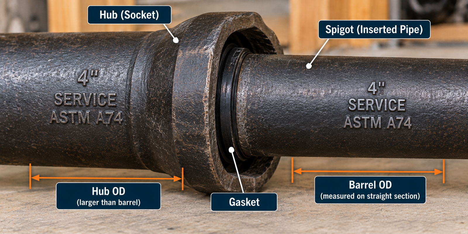
In a hub-and-spigot joint, the spigot (plain end) slides into the hub of the next pipe or fitting, with a compression gasket between them. ASTM A74 gives dimensions for the barrel, hub, spigot and fittings.
| Nominal size | SV barrel OD | SV hub ID | SV telescoping length | XH barrel OD | XH hub ID | XH telescoping length |
|---|---|---|---|---|---|---|
| 2″ | 2.30 | 2.94 | 2.50 | 2.38 | 3.06 | 2.50 |
| 3″ | 3.30 | 3.94 | 2.75 | 3.50 | 4.19 | 2.75 |
| 4″ | 4.30 | 4.94 | 3.00 | 4.50 | 5.19 | 3.00 |
| 5″ | 5.30 | 5.94 | 3.00 | 5.50 | 6.19 | 3.00 |
| 6″ | 6.30 | 6.94 | 3.00 | 6.50 | 7.19 | 3.00 |
| 8″ | 8.38 | 9.25 | 3.50 | 8.62 | 9.50 | 3.50 |
| 10″ | 10.50 | 11.38 | 3.50 | 10.75 | 11.62 | 3.50 |
| 12″ | 12.50 | 13.50 | 4.24 | 12.75 | 13.75 | 4.25 |
| 15″ | 15.88 | 16.95 | 4.25 | 15.88 | 16.95 | 4.25 |
Hub inside diameter (A), barrel OD (J) and telescoping length (Y) are one manufacturer’s published values. Do not infer a hub diameter from the barrel OD table.
Figure 3. No-Hub joint and hub-and-spigot joint, schematic. The barrel OD and hub diameter are different dimensions.
Hubless Cast Iron Pipe and Couplings
Plain ends, gasket, shield and clamps.
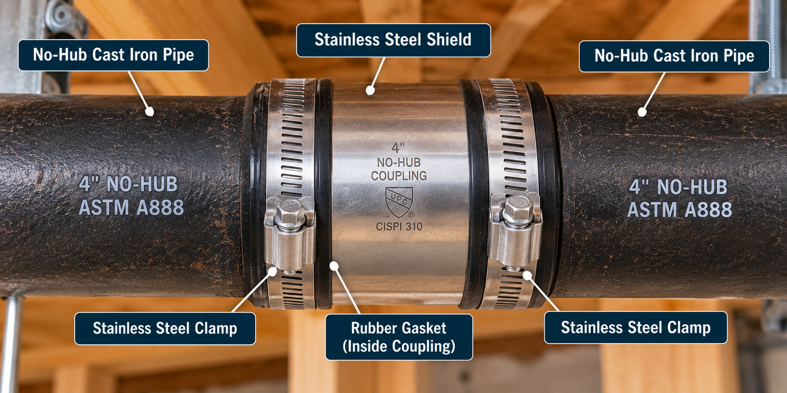
Hubless joints use a plain-ended pipe on each side and a shielded coupling.
- An elastomeric gasket seals the joint.
- A metallic (stainless-steel) shield covers the gasket.
- A clamping system compresses the assembly.
- The coupling must be compatible with the pipe, fittings and application.
ASTM C1277-26 covers shielded hubless couplings for hubless cast iron soil pipe and fittings. Heavy-duty couplings are covered by ASTM C1540-26.
Not every coupling has the same width or installation torque. Follow the coupling manufacturer’s instructions.
Equipment for Your Project
Affiliate disclosure: As an Amazon Associate, ConcreteCalculate earns from qualifying purchases. We may also earn a commission from other affiliate links at no additional cost to you.
Cast Iron Pipe Coupling Size Chart
Shield width and clamp count by nominal size, with limits.
Coupling sizes follow the nominal pipe size, but the pipe type sets the OD that the coupling must fit. A coupling labeled 4 in is not proof of a fit on every 4-inch cast iron pipe.
| Nominal size | No-Hub pipe OD (in) | Standard coupling: CISPI 310 / ASTM C1277 (width / clamps) | Heavy-duty: ASTM C1540 (width / clamps) |
|---|---|---|---|
| 1-1/2″ | 1.90 | 2.13 in / 2 | 3.00 in / 4 |
| 2″ | 2.35 | 2.13 in / 2 | 3.00 in / 4 |
| 3″ | 3.35 | 2.13 in / 2 | 3.00 in / 4 |
| 4″ | 4.38 | 2.13 in / 2 | 3.00 in / 4 |
| 5″ | 5.30 | 3.00 in / 4 | 4.00 in / 6 |
| 6″ | 6.30 | 3.00 in / 4 | 4.00 in / 6 |
| 8″ | 8.38 | 4.00 in / 4 | 4.00 in / 6 |
| 10″ | 10.56 | 4.00 in / 4 | 4.00 in / 6 |
Shield width and clamp count are manufacturer catalog values for the named products. For 12 and 15 in, one manufacturer lists 5.50 in wide, 6-clamp couplings. No torque values are shown; use the coupling manufacturer’s instructions.
- Use the coupling manufacturer’s data to confirm the OD range it covers.
- Hubless couplings are for plain-ended pipe. Hub-and-spigot pipe uses compression gaskets sized for Service or Extra Heavy.
- Transition between pipe types needs an adapter or a coupling rated for both.
Cast Iron Pipe Weight and Lengths
A product-specific weight example and standard length notes.
Weight depends on nominal size, wall, pipe class, product geometry, length and whether a hub is present. Do not calculate commercial weight from nominal wall alone.
| Nominal size | No-Hub | Service (single hub) | Extra Heavy (single hub) |
|---|---|---|---|
| 2″ | 35.0 | 40.1 | 45.3 |
| 3″ | 54.0 | 59.5 | 83.9 |
| 4″ | 76.0 | 75.1 | 110.2 |
| 6″ | 117.8 | 122.8 | 156.6 |
| 8″ | 170.9 | 189.9 | 246.1 |
Weights are one manufacturer’s approximate values for shipping purposes. Other manufacturers and product lines can differ.
See the Pipe Weight Chart and the Pipe Weight Calculator for other pipe materials.
Pipe lengths
ASTM A74 recognizes 2-1/2, 3-1/2, 5 and 10 ft lengths for Service and Extra Heavy pipe. ASTM A888 covers hubless pipe in 5 ft and 10 ft lengths. Actual availability varies by product and manufacturer.
Cast Iron Pipe vs. PVC Pipe Dimensions
Two dimensional systems, not one.
PVC follows the IPS dimensional system, and cast iron soil pipe has its own. The PVC values are general IPS references; the cast iron values come from the data above. See the PVC Pipe Size Chart and the ABS Pipe Size Chart for plastic DWV pipe.
| Nominal size | No-Hub | Service | Extra Heavy | IPS Schedule 40 PVC |
|---|---|---|---|---|
| 2″ | 2.35 | 2.30 | 2.38 | 2.375 |
| 3″ | 3.35 | 3.30 | 3.50 | 3.500 |
| 4″ | 4.38 | 4.30 | 4.50 | 4.500 |
| 6″ | 6.30 | 6.30 | 6.50 | 6.625 |
At some sizes a number can look close, such as Extra Heavy 4-inch at 4.50 in and 4-inch IPS PVC at 4.500 in. A close OD does not make the joints interchangeable: the joint systems differ, and a nominal-size match does not establish coupling compatibility.
Cast Iron Pipe vs. Ductile Iron Pipe
Soil pipe and pressure pipe are not interchangeable.
Gray cast iron soil pipe is a non-pressure DWV product. Ductile iron pressure pipe is a different material and a different dimensional system.
| Nominal size | Cast iron soil pipe (No-Hub / Service / Extra Heavy) | Ductile iron pressure pipe (AWWA C151) |
|---|---|---|
| 4″ | 4.38 / 4.30 / 4.50 | 4.80 |
| 6″ | 6.30 / 6.30 / 6.50 | 6.90 |
| 8″ | 8.38 / 8.38 / 8.62 | 9.05 |
- Application: soil pipe for gravity drainage; ductile iron for pressurized water and similar service.
- Standards: ASTM A74 and A888 for soil pipe; AWWA standards such as C151/A21.51 for ductile iron.
- Joining and fittings differ, so do not mix them.
A full ductile iron dimensional chart is outside the scope of this page.
Cast Iron Soil Pipe vs. Historical Cast Iron Water Pipe
Do not apply soil pipe dimensions to old water mains.
Older underground mains may be cast iron pressure pipe with legacy dimensions. Do not treat ASTM A74 soil pipe dimensions as the dimensions of historical cast iron water mains.
- Identify the pipe’s original standard, class and approximate age.
- Measure the actual OD before choosing repair components.
- Use fittings and repair products made for that pipe system.
Cast Iron Pipe Flow Area and Capacity
Full-bore area from the inside diameter.
Cross-sectional flow area
- A = full-bore flow area (in²)
- ID = inside diameter (in)
4-Inch No-Hub Full-Bore Area
What it means: This is a geometric full-bore area, not an allowable DWV flow rate. With the published ID of 3.94 in the area is about 12.19 in².
Gravity drainage depends on slope, loading, venting, fittings and the applicable plumbing code.
For general hydraulics see the Pipe Flow Rate Chart, and for water volume per foot see the Pipe Volume Chart.
Cast Iron Pipe Support and Installation
Manufacturer guidance, not a universal spacing rule.
Cast iron is heavy, so support and alignment matter at every joint. Use the locally adopted plumbing code and the manufacturer’s instructions for actual requirements.
- Charlotte Pipe’s manual calls for horizontal pipe to be supported at every hub or coupling, with the hanger within 18 in of the joint.
- Where several joints fall within a 4 ft developed length, every other joint can be supported.
- Horizontal pipe and fittings of 5 in and larger must be braced against horizontal movement.
- The manual notes that most plumbing codes require 5 ft pipe to be supported at 5 ft intervals and 10 ft pipe at 10 ft intervals.
- Vertical pipe is secured at each stack base and at intervals that keep the system aligned.
Never test cast iron with compressed air or gas. Manufacturers specify hydrostatic testing to about 10 ft of head (4.3 psi).
For other materials, see the Pipe Support Spacing Chart. Buried pipe also needs correct bedding and corrosion consideration, so follow the manufacturer’s guidance.
ASTM A74 Cast Iron Soil Pipe
What the hub-and-spigot standard covers.
ASTM A74-25 covers cast gray iron soil pipe and fittings for gravity-flow plumbing, drain, waste and vent sanitary, and storm water applications.
- Covers Service and Extra Heavy classes.
- Sets requirements for material, manufacture, mechanical and chemical properties, coating, test methods, inspection, certification and markings.
- Includes dimensions and dimensional tolerances for pipe, hubs, spigots and fittings.
The pipe and fittings are not intended for pressure applications.
| Product category | Principal U.S. standard | Joint type | Intended service |
|---|---|---|---|
| Hubless (No-Hub) pipe and fittings | ASTM A888 / CISPI 301 | Compatible shielded hubless coupling | Gravity DWV and storm drainage |
| Service hub-and-spigot | ASTM A74 | Hub and spigot, compression gasket | Gravity DWV and storm drainage |
| Extra Heavy hub-and-spigot | ASTM A74 | Hub and spigot, compression gasket | Gravity DWV and storm drainage |
| Hubless couplings | CISPI 310 / ASTM C1277; heavy duty ASTM C1540 | Shielded elastomeric coupling | As permitted by listing and application |
| Compression gaskets | ASTM C564 | Hub-and-spigot compression joint | Applicable hub-and-spigot DWV systems |
ASTM A888 and CISPI 301 Hubless Pipe
The hubless standards, and what they are not.
ASTM A888-24 covers hubless cast iron soil pipe and fittings for use in gravity-flow sanitary, storm drain, waste and vent systems. It establishes requirements for material, manufacture, properties, dimensions, coating, test methods, inspection, certification and product marking.
CISPI 301 is a comparable Cast Iron Soil Pipe Institute specification, and the two are identified together as hubless product specifications. Both are for non-pressure applications.
Do not apply A888 or CISPI 301 dimensions to ASTM A74 Service or Extra Heavy pipe.
How to Measure Existing Cast Iron Pipe
A practical identification workflow.
Follow this sequence to identify an existing pipe before ordering parts.
Figure 4. Identify the pipe, measure the barrel OD, then compare with the chart.
- Identify the joint type: hubless or hub-and-spigot.
- Measure the plain barrel, not the hub or coupling.
- Compare the actual OD with the No-Hub, Service and Extra Heavy chart.
- Inspect markings for size, manufacturer, class and standard.
- Check the condition: corrosion, coating, ovality and damage.
- Verify the replacement product against the pipe and coupling manufacturer’s requirements.
One reading is not an identification
Old pipe may be coated, corroded, damaged or out of round. Average several readings and confirm with markings and the manufacturer.
Common Cast Iron Pipe Sizing Mistakes
Errors that lead to the wrong coupling or gasket.
Assuming nominal size equals OD
4-inch cast iron is not 4.000 in OD.
Assuming all 4-inch cast iron is the same
The OD is 4.38, 4.30 or 4.50 in.
Confusing No-Hub and Service
Different joints, ODs and fittings.
Confusing Service and Extra Heavy
A 0.20 in OD gap at 4 in.
Measuring the hub instead of the barrel
The hub is larger than the pipe OD.
Using steel Schedule 40 dimensions
Steel schedule tables do not describe soil pipe. See the Pipe Schedule Chart.
Assuming PVC and cast iron share ODs
They follow different systems.
Treating soil pipe as pressure pipe
It is a non-pressure DWV product.
Using calculated ID as exact bore
It is a nominal geometric value.
Ignoring corrosion and buildup
The real opening can be smaller.
Choosing couplings from nominal size alone
Confirm the OD range.
Mixing ductile iron and soil pipe standards
AWWA pressure pipe differs from A74/A888.
Assuming old and new pipe match
Historical products can differ.
Cast Iron Pipe Size FAQs
Short answers to common cast iron sizing questions.
Common cast iron soil pipe runs from 1-1/2 inch (No-Hub) or 2 inch (Service and Extra Heavy) up to 15 inch nominal. Availability varies by product and manufacturer, so confirm the pipe type before you size anything.
It depends on the type. Nominal 2-inch barrel OD is about 2.35 in for No-Hub, 2.30 in for Service and 2.38 in for Extra Heavy.
Nominal 3-inch barrel OD is about 3.35 in for No-Hub, 3.30 in for Service and 3.50 in for Extra Heavy.
Nominal 4-inch barrel OD is about 4.38 in for No-Hub, 4.30 in for Service and 4.50 in for Extra Heavy. There is no single 4-inch cast iron OD.
Nominal 6-inch barrel OD is about 6.30 in for No-Hub, 6.30 in for Service and 6.50 in for Extra Heavy.
Cast iron soil pipe is identified by nominal size, and the standards control the barrel OD and wall. A tabulated inside diameter is also published, with its own tolerance, so treat ID as a derived or toleranced value.
No-Hub (hubless) pipe has plain ends on both sides and is joined with a shielded hubless coupling. It is covered by ASTM A888 and CISPI 301.
Service (SV) is hub-and-spigot cast iron soil pipe covered by ASTM A74. It has a lighter wall than Extra Heavy and a smaller barrel OD at each nominal size.
Extra Heavy (XH) is hub-and-spigot cast iron soil pipe covered by ASTM A74, with a thicker wall added outward, so its barrel OD is larger than Service at the same nominal size.
No. They share nominal sizes but not outside diameters. For 4-inch pipe the nominal barrel ODs are 4.30 in and 4.50 in, a 0.20 in difference, so gaskets and fittings are not interchangeable.
No. Nominal 4-inch No-Hub barrel OD is about 4.38 in, while 4-inch IPS Schedule 40 PVC is 4.500 in. Matching nominal size does not mean matching OD or joint type.
Decide whether it is hubless or hub-and-spigot, then measure the plain barrel (not the hub) with calipers or a tape, average a few readings, and compare with the chart. Check markings and the condition of the pipe too.
ASTM A74 is the specification for cast iron soil pipe and fittings in Service and Extra Heavy classes, for gravity-flow plumbing, drain, waste, vent and storm applications. It is not intended for pressure service.
ASTM A888 is the specification for hubless cast iron soil pipe and fittings for sanitary and storm drain, waste and vent systems. It is intended for non-pressure, gravity-flow use.
CISPI 301 is the Cast Iron Soil Pipe Institute specification for hubless cast iron soil pipe and fittings, a companion to ASTM A888.
No. Cast iron soil pipe is a non-pressure DWV product. Manufacturers warn never to test it with compressed air or gas, and they specify hydrostatic tests to about 10 ft of head (4.3 psi).
No. Ductile iron pressure pipe follows AWWA standards and different dimensions, for example 4.80 in OD for 4-inch pipe. Do not mix its dimensions or fittings with cast iron soil pipe.
It depends on the pipe type. No-Hub pipe uses a shielded hubless coupling, hub-and-spigot pipe uses a compression gasket sized for Service or Extra Heavy, and transitions need a matching adapter. Confirm the OD range with the coupling manufacturer.
Print This Cast Iron Pipe Size Chart
Use your browser to save this page as a PDF for a job-site binder or estimating folder. Interactive sections are hidden when printing.
![Rebar Size Chart - Complete #3 to No. 20 [64] Diameter, Area & Grade Reference](https://concretecalculate.com/wp-content/uploads/2026/07/Rebar-Size-Chart-2026-Complete-3-to-No.-20-64-Diameter-Area-Grade-Reference-390x220.png)