CPVC Pipe Size Chart 2026 – OD, ID and Wall Thickness
CPVC Pipe Size ChartOD, ID and Wall Thickness
CTS SDR 11 and IPS Schedule 40/80 CPVC dimensions, with actual OD, minimum wall, calculated ID, the standards behind them and the formulas to check them.
 Reviewed by Muhammad Ramzan Babar, PhD Researcher (Plasma Physics) & Calculator Developer | View Profile
Quick Answer: CPVC Has More Than One Size System
- Residential and commercial hot and cold water CPVC is usually CTS SDR 11 (ASTM D2846): 1/2 in nominal = 0.625 in OD, 3/4 in = 0.875 in, 1 in = 1.125 in, 2 in = 2.125 in.
- Industrial CPVC is usually IPS Schedule 40 or 80 (ASTM F441): 1/2 in nominal = 0.840 in OD, 1 in = 1.315 in, 2 in = 2.375 in.
- Nominal size is never the measured OD, and CTS and IPS fittings are not interchangeable by nominal label.
CPVC Pipe Size Chart
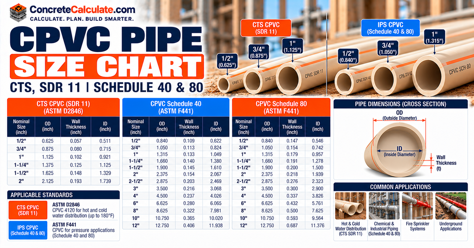
CTS SDR 11 quick reference: nominal size, actual OD, minimum wall and calculated ID.
Always identify whether the CPVC is CTS, IPS Schedule, or another SDR system before using a dimensional table. The chart below is the CTS SDR 11 system defined by ASTM D2846/D2846M-24, the one used for hot and cold potable water distribution in houses and commercial buildings.
| Nominal CTS size | Actual OD (in) | OD (mm) | Min. wall (in) | Min. wall (mm) | Calc. ID (in)* | Calc. ID (mm)* |
|---|---|---|---|---|---|---|
| 1/2″ | 0.625 | 15.9 | 0.068 | 1.73 | 0.489 | 12.4 |
| 3/4″ | 0.875 | 22.2 | 0.080 | 2.03 | 0.715 | 18.2 |
| 1″ | 1.125 | 28.6 | 0.102 | 2.59 | 0.921 | 23.4 |
| 1-1/4″ | 1.375 | 34.9 | 0.125 | 3.17 | 1.125 | 28.6 |
| 1-1/2″ | 1.625 | 41.3 | 0.148 | 3.76 | 1.329 | 33.8 |
| 2″ | 2.125 | 54.0 | 0.193 | 4.90 | 1.739 | 44.2 |
*Calculated ID = OD – 2 x minimum wall. It is a geometric estimate from minimum wall, not a guaranteed or average bore. Millimeter values are converted at 25.4 mm per inch.
How to read this chart
Find your nominal CTS size in the first column, then read across for the controlled outside diameter, the minimum wall and the calculated inside diameter. Dimensions are for plain-end pipe and tubing. Wall thickness is a minimum, so actual walls run slightly thicker.
Source and product notes
OD and minimum wall values match the ASTM D2846 dimensions published in current manufacturer data for SDR 11 CTS CPVC (for example, Charlotte Pipe FlowGuard Gold). Some older literature lists a 0.060 in minimum wall for 1/2-in tubing, so confirm the wall against the datasheet for the exact product you are buying.
A pressure rating is not part of the size
Charlotte Pipe rates its ASTM D2846 SDR 11 CTS pipe at 400 psi at 73°F. That is a product rating at one temperature, not a universal CPVC rating. See the pressure and derating sections below.
How to Read CPVC Pipe Dimensions
Definitions for nominal size, OD, wall, ID, SDR and Schedule.
Five separate quantities appear in CPVC data. Keep them separate, because mixing them is the most common sizing error.
Nominal size
A trade designation used to name the pipe. It is not the measured OD or ID.
Outside diameter (OD)
The controlled outside dimension. Sockets and fittings are sized from it.
Wall thickness (t)
The minimum material thickness required by the dimensional standard.
Inside diameter (ID)
The bore. It is estimated from OD and wall, so treat it as calculated.
SDR
Standard dimension ratio: OD divided by minimum wall. A lower SDR means a relatively thicker wall.
Schedule
A wall-thickness series used by IPS CPVC (Schedule 40 and 80). Wall changes with nominal size.
For broader comparisons across materials, see the Pipe Outside Diameter Chart and the Pipe Inside Diameter Chart. This page stays focused on CPVC.
Figure 1. CPVC pipe cross-section showing OD, ID and wall thickness. The diagram is schematic and not drawn to a specific pipe size.
CTS vs. IPS CPVC Pipe
Same nominal size, different outside diameter.
CTS means Copper Tube Size. CTS CPVC is made to the outside diameters of copper water tube (see the Copper Pipe Size Chart). IPS means Iron Pipe Size. IPS CPVC uses the same outside diameters as steel pipe of the same nominal size.
| Nominal size | CTS OD (in) | IPS OD (in) | Difference (in) |
|---|---|---|---|
| 1/2″ | 0.625 | 0.840 | 0.215 |
| 3/4″ | 0.875 | 1.050 | 0.175 |
| 1″ | 1.125 | 1.315 | 0.190 |
| 1-1/4″ | 1.375 | 1.660 | 0.285 |
| 1-1/2″ | 1.625 | 1.900 | 0.275 |
| 2″ | 2.125 | 2.375 | 0.250 |
IPS outside diameters are the standard IPS values used for ASTM F441 Schedule 40 and 80 pipe.
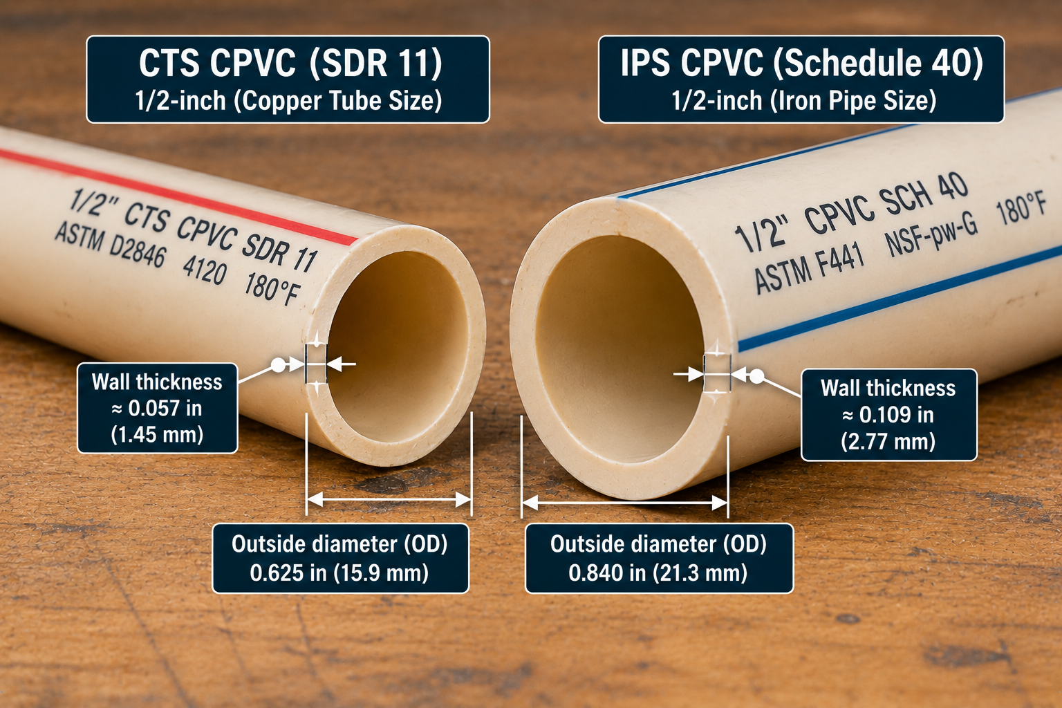
The practical rule: 1-in CTS CPVC has a 1.125 in OD and 1-in IPS CPVC has a 1.315 in OD. A nominal size label alone cannot establish fitting compatibility.
Figure 2. 1-inch CTS and 1-inch IPS CPVC drawn at identical scale. The IPS section is shown with a Schedule 40 wall.
Do not join CTS and IPS directly
The two systems have different outside diameters. Where they meet, use an approved transition fitting or method.
ASTM D2846 CTS CPVC Size Chart
What the standard covers and where the CTS dimensions come from.
ASTM D2846/D2846M-24 is the active specification for CPVC hot and cold water distribution systems. It covers pipe and tubing, socket-type fittings, street fittings, plastic-to-metal transition fittings, solvent cements and adhesives made in a single dimension ratio.
- Intended for residential and commercial, hot and cold, potable water distribution.
- CPVC 4120 pipe, tubing and fittings, classified as SDR 11.
- Water service up to and including 180°F (82°C).
- Requirements for materials, workmanship, dimensions and tolerances, hydrostatic sustained pressure strength and thermocycling resistance.
- Intended for chemically compatible pressurized liquids only.
The complete CTS size range in the table above (1/2 through 2 inch nominal) is the range commonly produced by U.S. manufacturers for this system. Larger sizes in the same buildings are usually supplied as IPS Schedule CPVC.
SDR 11 CPVC Pipe Dimensions
How the ratio works, and why published values still govern.
SDR formula
- OD = outside diameter (in)
- t = minimum wall thickness (in)
- SDR = 11 for ASTM D2846 CPVC
Because SDR is a ratio, every CTS size has the same relative wall. Published tables are still the authority, since very small sizes are governed by a minimum wall and values are rounded to three decimals. For 1/2-in tubing, OD / 11 = 0.057 in, yet the published minimum wall is 0.068 in.
| Nominal CTS size | OD (in) | OD / 11 (in) | Published min. wall (in) |
|---|---|---|---|
| 1/2″ | 0.625 | 0.057 | 0.068 |
| 3/4″ | 0.875 | 0.080 | 0.080 |
| 1″ | 1.125 | 0.102 | 0.102 |
| 1-1/4″ | 1.375 | 0.125 | 0.125 |
| 1-1/2″ | 1.625 | 0.148 | 0.148 |
| 2″ | 2.125 | 0.193 | 0.193 |
CPVC Wall Thickness Calculation
Checking a published wall against the SDR ratio.
Wall thickness calculation
1-Inch CTS CPVC Minimum Wall
What it means: The formula and the published value agree to three decimals for 1-inch CTS. This is an illustrative check, not a replacement for the standard’s table.
CPVC Inside Diameter Calculation
From OD and minimum wall to a calculated bore.
Inside diameter calculation
- OD = outside diameter (in)
- t = wall thickness (in)
- ID = calculated inside diameter (in)
1-Inch CTS CPVC Calculated ID
What it means: Because minimum wall is used, this is the largest bore the geometry allows. Real tubing has a slightly thicker average wall, so its bore is slightly smaller. One manufacturer lists an average ID of 0.901 in for the same size.
Calculated is not guaranteed
Treat every calculated ID in this chart as a reference estimate. For hydraulic design, use the manufacturer’s published ID for the exact product, and see the Pipe Inside Diameter Chart for general ID references.
1/2-Inch CPVC Dimensions
CTS SDR 11 values, with the IPS difference noted.
1/2-inch CTS SDR 11
OD 0.625 in
Min. wall 0.068 in, calculated ID 0.489 in (15.9 mm OD)
For comparison, 1/2-in IPS CPVC has OD 0.840 in, Schedule 40 wall 0.109 in and Schedule 80 wall 0.147 in.
Reading 1/2-inch CPVC
This is the most common branch-line size in residential supply plumbing. Because the minimum wall (0.068 in) is thicker than OD / 11, the calculated ID of 0.489 in is smaller than a pure SDR calculation would suggest.
A 1/2-in IPS product is a different dimensional system and is not a drop-in match for CTS fittings.
3/4-Inch CPVC Dimensions
CTS SDR 11 values, kept separate from IPS.
3/4-inch CTS SDR 11
OD 0.875 in
Min. wall 0.080 in, calculated ID 0.715 in (22.2 mm OD)
For comparison, 3/4-in IPS CPVC has OD 1.050 in, Schedule 40 wall 0.113 in and Schedule 80 wall 0.154 in.
Reading 3/4-inch CPVC
3/4-in CTS is a common size for water heater connections and trunk lines in houses. Its OD of 0.875 in is 0.175 in smaller than 3/4-in IPS.
Keep IPS dimensions in the separate Schedule 40 and 80 tables below.
1-Inch CPVC Dimensions
The most searched size, and the clearest CTS versus IPS example.
1-inch CTS SDR 11
OD 1.125 in
Min. wall 0.102 in, calculated ID 0.921 in (28.6 mm OD)
For comparison, 1-in IPS CPVC has OD 1.315 in, Schedule 40 wall 0.133 in and Schedule 80 wall 0.179 in.
Why 1-inch is the key comparison
1-in CTS is 1.125 in OD and 1-in IPS is 1.315 in OD, a 0.190 in (4.8 mm) difference. This is the size where CTS and IPS get confused most often.
1-1/4, 1-1/2 and 2-Inch CPVC Dimensions
The larger common CTS plumbing sizes.
Larger CTS plumbing sizes follow the same SDR 11 pattern. Values below are plain-end CTS dimensions and should be confirmed against the product datasheet.
| Nominal CTS size | Actual OD (in) | Min. wall (in) | Calc. ID (in)* |
|---|---|---|---|
| 1-1/4″ | 1.375 | 0.125 | 1.125 |
| 1-1/2″ | 1.625 | 0.148 | 1.329 |
| 2″ | 2.125 | 0.193 | 1.739 |
Schedule 40 CPVC Pipe Size Chart
IPS Schedule 40 outside diameter, minimum wall and calculated ID.
This section switches from CTS to IPS. ASTM F441/F441M-23 covers CPVC pipe in Schedule 40 and Schedule 80, using the same outside diameters as steel pipe. For the cross-material schedule system, see the Pipe Schedule Chart and the general Schedule 40 Pipe Chart.
| NPS | OD (in) | OD (mm) | Min. wall (in) | Calc. ID (in)* | Calc. ID (mm)* |
|---|---|---|---|---|---|
| 1/2″ | 0.840 | 21.3 | 0.109 | 0.622 | 15.8 |
| 3/4″ | 1.050 | 26.7 | 0.113 | 0.824 | 20.9 |
| 1″ | 1.315 | 33.4 | 0.133 | 1.049 | 26.6 |
| 1-1/4″ | 1.660 | 42.2 | 0.140 | 1.380 | 35.1 |
| 1-1/2″ | 1.900 | 48.3 | 0.145 | 1.610 | 40.9 |
| 2″ | 2.375 | 60.3 | 0.154 | 2.067 | 52.5 |
| 2-1/2″ | 2.875 | 73.0 | 0.203 | 2.469 | 62.7 |
| 3″ | 3.500 | 88.9 | 0.216 | 3.068 | 77.9 |
| 4″ | 4.500 | 114.3 | 0.237 | 4.026 | 102.3 |
| 6″ | 6.625 | 168.3 | 0.280 | 6.065 | 154.1 |
| 8″ | 8.625 | 219.1 | 0.322 | 7.981 | 202.7 |
| 10″ | 10.750 | 273.1 | 0.365 | 10.020 | 254.5 |
| 12″ | 12.750 | 323.8 | 0.406 | 11.938 | 303.2 |
*Calculated ID = OD – 2 x minimum wall. IPS dimensions only. Do not mix CTS SDR 11 values into this table. Sizes and availability vary by manufacturer.
Schedule 80 CPVC Pipe Size Chart
IPS Schedule 80 outside diameter, minimum wall and calculated ID.
Schedule 80 CPVC uses the same IPS outside diameter as Schedule 40 but a thicker wall. For general Schedule 80 references across materials, see the Schedule 80 Pipe Chart.
| NPS | OD (in) | OD (mm) | Min. wall (in) | Calc. ID (in)* | Calc. ID (mm)* |
|---|---|---|---|---|---|
| 1/2″ | 0.840 | 21.3 | 0.147 | 0.546 | 13.9 |
| 3/4″ | 1.050 | 26.7 | 0.154 | 0.742 | 18.8 |
| 1″ | 1.315 | 33.4 | 0.179 | 0.957 | 24.3 |
| 1-1/4″ | 1.660 | 42.2 | 0.191 | 1.278 | 32.5 |
| 1-1/2″ | 1.900 | 48.3 | 0.200 | 1.500 | 38.1 |
| 2″ | 2.375 | 60.3 | 0.218 | 1.939 | 49.3 |
| 2-1/2″ | 2.875 | 73.0 | 0.276 | 2.323 | 59.0 |
| 3″ | 3.500 | 88.9 | 0.300 | 2.900 | 73.7 |
| 4″ | 4.500 | 114.3 | 0.337 | 3.826 | 97.2 |
| 6″ | 6.625 | 168.3 | 0.432 | 5.761 | 146.3 |
| 8″ | 8.625 | 219.1 | 0.500 | 7.625 | 193.7 |
| 10″ | 10.750 | 273.1 | 0.593 | 9.564 | 242.9 |
| 12″ | 12.750 | 323.8 | 0.687 | 11.376 | 289.0 |
Schedule relationship at the same NPS
Equipment for Your Project
Affiliate disclosure: As an Amazon Associate, ConcreteCalculate earns from qualifying purchases. We may also earn a commission from other affiliate links at no additional cost to you.
Schedule 40 vs. Schedule 80 CPVC
Same outside diameter, different wall, bore and weight.
| NPS | OD (in) | Sch. 40 wall (in) | Sch. 40 calc. ID (in) | Sch. 80 wall (in) | Sch. 80 calc. ID (in) | Wall increase |
|---|---|---|---|---|---|---|
| 1/2″ | 0.840 | 0.109 | 0.622 | 0.147 | 0.546 | +35% |
| 3/4″ | 1.050 | 0.113 | 0.824 | 0.154 | 0.742 | +36% |
| 1″ | 1.315 | 0.133 | 1.049 | 0.179 | 0.957 | +35% |
| 1-1/4″ | 1.660 | 0.140 | 1.380 | 0.191 | 1.278 | +36% |
| 1-1/2″ | 1.900 | 0.145 | 1.610 | 0.200 | 1.500 | +38% |
| 2″ | 2.375 | 0.154 | 2.067 | 0.218 | 1.939 | +42% |
| 3″ | 3.500 | 0.216 | 3.068 | 0.300 | 2.900 | +39% |
| 4″ | 4.500 | 0.237 | 4.026 | 0.337 | 3.826 | +42% |
| 6″ | 6.625 | 0.280 | 6.065 | 0.432 | 5.761 | +54% |
Figure 3. 1-inch IPS CPVC Schedule 40 and Schedule 80 at equal scale. Wall and ID values are minimum-wall geometry.
Approximate weight
| NPS | Sch. 40 (lb/ft) | Sch. 80 (lb/ft) |
|---|---|---|
| 1/2″ | 0.17 | 0.22 |
| 1″ | 0.34 | 0.44 |
| 2″ | 0.74 | 1.02 |
| 4″ | 2.20 | 3.05 |
Typical published CPVC pipe weights; actual weight depends on the manufacturer and compound.
- Same IPS OD, thicker wall, smaller ID for Schedule 80.
- More material per foot, so more weight and higher cost.
- Pressure capability depends on size, material, temperature and the manufacturer rating, not on the schedule number alone.
- Same nominal size does not mean the same flow area.
Schedule 80 is not automatically the high-pressure answer
Do not assume Schedule 80 is always required for higher pressure. Check the pressure rating for the actual size and operating temperature.
CTS SDR 11 vs. Schedule 40/80 CPVC
Two major systems compared feature by feature.
| Feature | CTS SDR 11 CPVC | IPS Schedule CPVC |
|---|---|---|
| Dimensional basis | Copper tube size (CTS) | Iron pipe size (IPS) |
| Wall system | SDR 11 | Schedule 40 or 80 |
| Primary standard | ASTM D2846/D2846M | ASTM F441/F441M |
| Typical context | Hot and cold potable water distribution | Industrial and process pressurized liquids; some plumbing and commercial use |
| Same OD at same nominal size? | No | No |
The two systems solve different problems. Treat them as separate product families with their own pipe, fittings and ratings.
Fittings must match the system
Do not use Schedule 40 or 80 dimensions for CTS SDR 11 CPVC, and do not use CTS dimensions for IPS CPVC.
ASTM F441 CPVC Pipe
The standard behind IPS Schedule 40 and 80 CPVC.
ASTM F441/F441M-23 covers CPVC pipe made in Schedule 40 and 80 sizes and pressure rated for water. The pipe is intended for chemically compatible pressurized liquids.
- Classification of CPVC pipe materials and a system of nomenclature for CPVC pipe.
- Dimensions, including the Schedule 40 and 80 wall tables.
- Sustained pressure, burst pressure and flattening resistance.
- Workmanship, extrusion quality and marking.
It is a pipe specification. It does not by itself make a product suitable for potable water or approved by a plumbing code.
ASTM F442 SDR-PR CPVC Pipe
A third CPVC dimensional system, noted for context.
ASTM F442/F442M covers CPVC pipe made in standard thermoplastic pipe dimension ratios and pressure rated for water. Earlier editions list SDR 11, 13.5, 17, 21, 26 and 32.5, with the pressure rating uniform across sizes for a given material and SDR.
That is why “CPVC equals CTS SDR 11” is not universally correct. Detailed F442 tables are outside the scope of this chart.
CPVC Pressure Rating
What controls it, and what this page does not claim.
CPVC pressure capability depends on the pipe system, size, wall thickness (SDR or Schedule), compound, temperature, the applicable standard and the manufacturer rating. A single number cannot describe all CPVC.
CTS SDR 11 example
Charlotte Pipe rates its ASTM D2846 SDR 11 CTS pipe at 400 psi at 73°F for water.
IPS Schedule example
Pressure varies by size. One manufacturer lists Schedule 80 maximum working pressure at 73°F from 1,130 psi at 1/4 in down to 230 psi at 12 in.
400 psi at 73°F is not 400 psi at 180°F
Never carry a room-temperature rating into hot water service.
For a cross-material overview of pressure behavior, see the Pipe Pressure Rating Chart.
CPVC Temperature and Pressure Derating
A reference-level look at how temperature reduces pressure capability.
CPVC loses pressure capability as temperature rises. ASTM D2846 covers hot and cold water service up to and including 180°F, but the allowable pressure at elevated temperature must come from the specific product or system rating. The table below applies published derating factors to a 400 psi at 73°F CTS SDR 11 product.
| Operating temperature | Derating factor | Max. pressure (psi) = 400 × factor |
|---|---|---|
| 73 to 80°F | 1.00 | 400 |
| 90°F | 0.91 | 364 |
| 100°F | 0.82 | 328 |
| 120°F | 0.65 | 260 |
| 140°F | 0.50 | 200 |
| 160°F | 0.40 | 160 |
| 180°F | 0.25 | 100 |
Reference example only. Factors are those published for ASTM D2846 CTS SDR 11 CPVC piping by manufacturers and distributors; maximum pressure is computed as 400 psi multiplied by the factor, so published tables may show slightly rounded numbers. Use your manufacturer’s table for design. No uprating applies below 73°F.
IPS Schedule CPVC derates too
Schedule CPVC factors are applied to the size-specific 73°F rating and extend to higher temperatures than CTS plumbing. Do not reuse this CTS table for IPS pipe.
CPVC vs. PVC Pipe Dimensions
Same size only within the same dimensional system.
Compare CPVC with PVC by dimensional system, not by material name. For IPS Schedule 40 and 80, CPVC and PVC share familiar outside diameters and wall thicknesses. CTS SDR 11 CPVC uses copper tube outside diameters, which differ from IPS PVC pressure pipe. The full PVC reference is the PVC Pipe Size Chart.
| System | Nominal 1 inch OD (in) | Same OD as IPS PVC? |
|---|---|---|
| CTS SDR 11 CPVC | 1.125 | No |
| IPS Schedule 40 or 80 CPVC | 1.315 | Yes, same IPS OD as Schedule 40/80 PVC |
Never say “CPVC and PVC are the same size” without naming the system. CPVC also tolerates higher service temperatures than PVC, which is why it is used for hot water.
CPVC Pipe Flow Area
Cross-sectional area from the calculated ID.
Cross-sectional flow area
- A = flow area (in²)
- ID = calculated inside diameter (in)
1-Inch CTS CPVC Flow Area
What it means: This is a geometric example based on calculated minimum-wall ID. For comparison, 1-in Schedule 40 IPS (ID 1.049 in) is 0.864 in² and Schedule 80 (ID 0.957 in) is 0.719 in², which is about 16.8% less area than Schedule 40.
Real hydraulic sizing also depends on length, fittings, pressure, allowable velocity and friction losses. Continue to the Pipe Flow Rate Chart for flow guidance, or the Pipe Volume Chart for the water held per foot.
CPVC Fittings and Dimensional Compatibility
Matching fittings to the correct CPVC system.
Fittings must match the pipe’s dimensional system. CTS pipe and tubing go with CTS socket fittings, and IPS Schedule pipe goes with IPS Schedule fittings. Socket dimensions are specific to each system.
- CTS to IPS joints need an approved transition fitting or method, never a forced fit.
- Threaded transitions to metal need the correct CPVC-to-metal fitting. For thread types, see the Pipe Thread Chart.
- ASTM D2846 explicitly includes socket-type fittings and plastic-to-metal transition fittings as part of the system.
Support spacing for CPVC is also system specific. Use the manufacturer’s data and the Pipe Support Spacing Chart only as a general reference.
CPVC Solvent Cement and Joining
A short joining overview, not an installation manual.
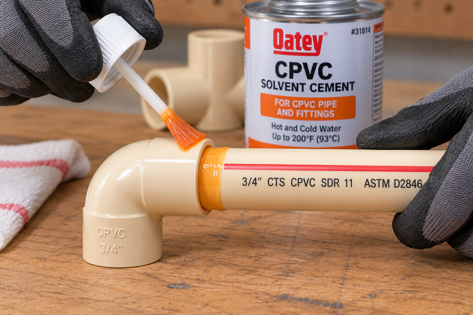
ASTM F493-22 (2026) covers solvent cements for CPVC pipe, tubing and socket-type fittings. Use cement made for CPVC, not general-purpose or PVC cement, unless the cement is explicitly rated for CPVC.
- Pipe and fitting must be compatible and from the same dimensional system.
- Cut square, deburr and clean the pipe end and socket.
- Follow the manufacturer’s instructions for primer, application, set time and cure time before pressure testing, which vary with size and temperature.
Potable-Water Certification and Pipe Markings
Reading the print line and separating standard, listing and code.
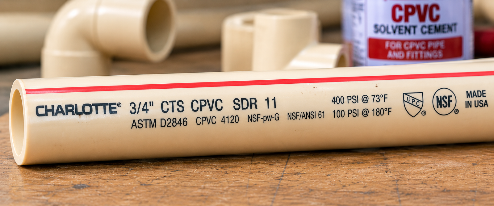
The print line on the pipe tells you what the product actually is. Look for:
- Manufacturer and CPVC material designation.
- Nominal size and the dimensional system (CTS, or IPS with Schedule).
- SDR or Schedule.
- The ASTM standard, such as D2846 or F441.
- Pressure and temperature information where printed.
- Certification marks, for example NSF listings.
Standard, certification and code are three different things
ASTM D2846 sets dimensional and performance requirements. NSF listings, including NSF/ANSI/CAN 61 for drinking-water contact, are third-party certification. Plumbing-code acceptance is decided by the code and your local authority. Verify the certification status of the actual product.
How to Select CPVC Pipe Size
A step-by-step workflow from application to certification.
The decision path runs from application to standard to size system, then to size, wall, temperature, pressure and fittings.
Figure 4. CPVC sizing system decision map. This is selection guidance, not code authorization; plumbing or mechanical code, project specification and manufacturer listing govern.
- Identify the application.
- Decide potable water or industrial and process use.
- Identify the applicable code and project specification.
- Select the CTS or IPS dimensional system.
- Select the nominal size.
- Confirm the actual OD.
- Select the SDR or Schedule.
- Confirm wall thickness and ID.
- Check pressure at the operating temperature.
- Verify chemical compatibility.
- Select matching fittings.
- Select the approved joining system.
- Verify product certification or listing where required.
If you are comparing CPVC with other residential supply pipe, the PEX Pipe Size Chart and the Pipe Size Chart cover those systems.
Common CPVC Pipe Sizing Mistakes
Most errors come from treating CPVC as one size system.
Assuming nominal size equals OD
1/2-in CTS is 0.625 in OD and 1/2-in IPS is 0.840 in OD.
Confusing CTS with IPS
They use different outside diameters and fittings.
Assuming 1-in CTS equals 1-in IPS
1.125 in versus 1.315 in OD.
Mixing CTS and IPS fittings
Use the correct fitting system or an approved transition.
Calling all CPVC SDR 11
IPS and other SDR systems exist.
Calling all CPVC Schedule 40 or 80
CTS plumbing tubing is SDR 11.
Assuming Schedule 80 changes OD
Only the wall changes; OD stays the same.
Treating calculated ID as guaranteed
Calculated from minimum wall; real bore varies.
Ignoring temperature on pressure
Rating drops as temperature rises.
Assuming all CPVC is potable certified
Check the product certification.
Using PVC cement on CPVC
Use cement specified for CPVC.
Ignoring chemical compatibility
Some oils, solvents and sealants attack CPVC.
Confusing D2846 with F441
One is CTS SDR 11, the other is IPS Schedule.
Using steel pipe dimensions for CTS CPVC
Steel IPS values do not apply to CTS tubing.
CPVC Pipe Size FAQs
Short answers to common CPVC sizing questions.
CPVC is made in more than one dimensional system. CTS (copper tube size) SDR 11 CPVC for hot and cold water distribution is commonly produced in nominal sizes from 1/2 inch through 2 inches. IPS Schedule 40 and Schedule 80 CPVC covers a wider range, shown here from 1/2 inch through 12 inches. Availability varies by manufacturer.
1/2-in CTS CPVC has an outside diameter of 0.625 in (15.9 mm). 1/2-in IPS Schedule CPVC has an outside diameter of 0.840 in (21.3 mm). The nominal label alone does not tell you which one you have.
3/4-in CTS CPVC measures 0.875 in (22.2 mm) OD. 3/4-in IPS Schedule CPVC measures 1.050 in (26.7 mm) OD.
1-in CTS CPVC measures 1.125 in (28.6 mm) OD. 1-in IPS Schedule CPVC measures 1.315 in (33.4 mm) OD, a difference of 0.190 in.
Dimensional standards control the outside diameter and a minimum wall thickness. The inside diameter is not the controlling size; it is estimated as OD minus twice the wall thickness, and the real bore varies with manufacturing tolerance.
No. Nominal size is a trade designation. For CTS CPVC, 1/2 inch nominal has a 0.625 in OD, and for IPS CPVC, 1/2 inch nominal has a 0.840 in OD. Neither equals 0.500 in.
CTS stands for Copper Tube Size. CTS CPVC is made to the outside diameters of copper water tube, with SDR 11 walls, and is covered by ASTM D2846/D2846M for hot and cold potable water distribution systems up to and including 180°F (82°C).
IPS stands for Iron Pipe Size. IPS CPVC uses the same outside diameters as steel pipe of the same nominal size, with Schedule 40 or Schedule 80 wall thicknesses under ASTM F441/F441M.
SDR 11 means the standard dimension ratio is 11, so minimum wall thickness is about one eleventh of the outside diameter (SDR = OD / t). ASTM D2846 uses SDR 11 for its CPVC 4120 hot and cold water system. Very small sizes can be governed by a minimum wall rather than the simple ratio.
It depends on the product. CTS CPVC for residential plumbing is SDR 11, not a Schedule. Industrial IPS CPVC is made in Schedule 40 and Schedule 80. Check the print line on the pipe.
They use different outside diameters and different wall systems. 1-in CTS is 1.125 in OD with an SDR 11 wall, while 1-in IPS is 1.315 in OD with a Schedule 40 or 80 wall. CTS and IPS fittings are not interchangeable by nominal label.
At the same nominal size, both have the same IPS outside diameter. Schedule 80 has a thicker wall, so it has a smaller inside diameter, less flow area and more weight per foot.
Only within the same dimensional system. IPS Schedule 40 and Schedule 80 CPVC share familiar outside diameters and wall thicknesses with IPS Schedule 40 and 80 PVC. CTS SDR 11 CPVC uses copper tube outside diameters, which differ from IPS PVC pressure pipe.
Use ID = OD – 2t, where t is the wall thickness. For 1-in CTS CPVC, ID = 1.125 – 2(0.102) = 0.921 in. This is a calculated estimate from minimum wall, not a guaranteed bore.
ASTM D2846/D2846M is the specification for CPVC plastic hot and cold water distribution systems. It covers pipe and tubing, socket-type fittings, transition fittings, solvent cements and adhesives made in SDR 11 for service up to and including 180°F (82°C).
ASTM F441/F441M covers CPVC pipe made in Schedule 40 and Schedule 80 sizes, pressure rated for water and intended for chemically compatible pressurized liquids. It sets requirements for materials, dimensions, sustained pressure, burst pressure, flattening and extrusion quality.
ASTM D2846 CTS CPVC systems are covered for water service up to and including 180°F (82°C). Some IPS Schedule CPVC products are listed by manufacturers for higher temperatures with sharply reduced pressure ratings, so check the specific product data.
Yes. Pressure capability falls as temperature rises. One common CTS SDR 11 product is rated at 400 psi at 73°F, and the same product class is rated at 100 psi at 180°F. Always apply the manufacturer’s derating factors.
Print This CPVC Size Chart
Use your browser to save this page as a PDF for a job-site binder or estimating folder. Interactive sections are hidden when printing.