Pipe Wall Thickness Chart – Schedule 40, 80, 160 & Material Comparison
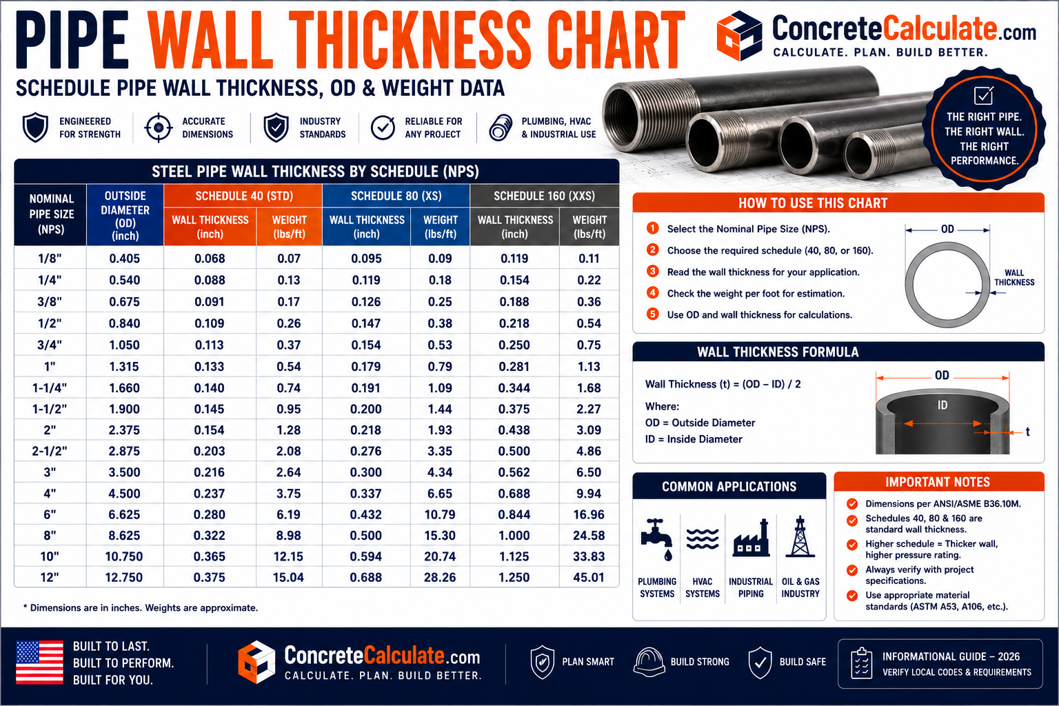
Pipe Wall Thickness Chart
Schedule 40, 80, 160 & Material Comparison
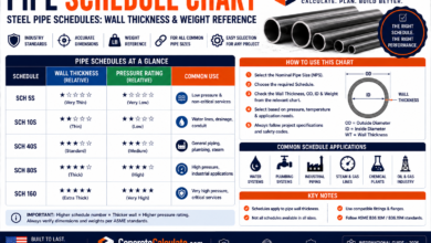
Schedule is a standardized wall thickness series, not a direct thickness value. This chart separates steel, stainless steel and PVC schedules by their actual governing standard.
 Reviewed by Muhammad Ramzan Babar, PhD Researcher & Calculator Developer · View Profile
Schedule is a standardized dimension series that must be read together with nominal pipe size (NPS). The same schedule number produces a different wall thickness at every different pipe size. Never assume a schedule number converts directly into a thickness value.
⭐⭐⭐ Pipe Wall Thickness: Quick Reference
Values follow ASME B36.10 for carbon and alloy steel pipe, the primary steel pipe dimensional standard.
| NPS | Outside Diameter | Schedule 40 Wall | Schedule 40 ID | Material/Standard |
|---|---|---|---|---|
| 1/2 | 0.840 in | 0.109 in | 0.622 in | Carbon/alloy steel (ASME B36.10) |
| 3/4 | 1.050 in | 0.113 in | 0.824 in | Carbon/alloy steel (ASME B36.10) |
| 1 | 1.315 in | 0.133 in | 1.049 in | Carbon/alloy steel (ASME B36.10) |
| 1-1/4 | 1.660 in | 0.140 in | 1.380 in | Carbon/alloy steel (ASME B36.10) |
| 1-1/2 | 1.900 in | 0.145 in | 1.610 in | Carbon/alloy steel (ASME B36.10) |
| 2 | 2.375 in | 0.154 in | 2.067 in | Carbon/alloy steel (ASME B36.10) |
| 2-1/2 | 2.875 in | 0.203 in | 2.469 in | Carbon/alloy steel (ASME B36.10) |
| 3 | 3.500 in | 0.216 in | 3.068 in | Carbon/alloy steel (ASME B36.10) |
| 4 | 4.500 in | 0.237 in | 4.026 in | Carbon/alloy steel (ASME B36.10) |
ASME B36.10 contains standardized dimensions for welded and seamless wrought carbon and alloy steel pipe, including the schedule-based wall thickness system used throughout this quick reference. Full schedule tables appear in dedicated sections below.
⭐ What Is Pipe Wall Thickness?
Wall thickness is the pipe material’s thickness between its outer and inner surfaces.
Outside diameter (OD)
The measured external diameter of the pipe.
Inside diameter (ID)
The internal flow diameter, the open space through which fluid or gas travels.
Wall thickness
The material thickness between OD and ID, calculated as (OD minus ID) divided by 2.
Why it matters
Wall thickness affects strength, weight, flow area, and (as one factor among several) pressure handling capability.
⭐⭐⭐ NPS vs Actual Outside Diameter
NPS is a standardized nominal designation, not a direct outside diameter measurement.
NPS 12 and smaller have outside diameters that are numerically larger than their corresponding nominal size label. For example, 1/2 inch NPS has an actual OD of 0.840 inches, not 0.500 inches. NPS 14 and larger have an actual OD that matches the nominal size in inches.
| NPS | Actual OD (in) | Actual OD (mm) |
|---|---|---|
| 1/2 | 0.840 | 21.34 |
| 3/4 | 1.050 | 26.67 |
| 1 | 1.315 | 33.40 |
| 1-1/4 | 1.660 | 42.16 |
| 1-1/2 | 1.900 | 48.26 |
| 2 | 2.375 | 60.33 |
| 3 | 3.500 | 88.90 |
| 4 | 4.500 | 114.30 |
| 6 | 6.625 | 168.28 |
| 8 | 8.625 | 219.08 |
| 10 | 10.750 | 273.05 |
| 12 | 12.750 | 323.85 |
| 14 | 14.000 | 355.60 |
| 16 | 16.000 | 406.40 |
⭐⭐⭐ What Is Pipe Schedule?
Schedule identifies a standardized wall thickness series, but the actual thickness value depends entirely on the pipe size it is paired with.
2 inch Schedule 40 does not have the same wall thickness as 4 inch Schedule 40. At 2 inch NPS, Schedule 40 wall thickness is 0.154 inches; at 4 inch NPS, Schedule 40 wall thickness is 0.237 inches. The schedule number identifies a position within a standardized thickness series, not a fixed universal value.
| Schedule | Applicable Standard | Material |
|---|---|---|
| 5, 5S | ASME B36.10 (5) / B36.19 (5S) | Steel / Stainless |
| 10, 10S | ASME B36.10 / B36.19 | Steel / Stainless |
| 20, 30 | ASME B36.10 | Steel |
| 40, 40S | ASME B36.10 / B36.19 | Steel / Stainless |
| 60 | ASME B36.10 | Steel |
| 80, 80S | ASME B36.10 / B36.19 | Steel / Stainless |
| 100, 120, 140, 160 | ASME B36.10 | Steel |
| STD, XS, XXS | ASME B36.10 | Steel |
Steel pipe schedules follow ASME B36.10. Stainless steel pipe schedules follow ASME B36.19, using S designations. Some B36.19 wall thicknesses differ from the equivalent B36.10 schedule at certain sizes, so these tables should never be treated as identical.
⭐⭐⭐ Steel Pipe: Schedule 40, 80 & 160 (ASME B36.10)
The primary carbon and alloy steel pipe dimensional reference.
| NPS | OD (in) | Sch 40 Wall | Sch 40 ID | Sch 80 Wall | Sch 80 ID |
|---|---|---|---|---|---|
| 1/2 | 0.840 | 0.109 | 0.622 | 0.147 | 0.546 |
| 3/4 | 1.050 | 0.113 | 0.824 | 0.154 | 0.742 |
| 1 | 1.315 | 0.133 | 1.049 | 0.179 | 0.957 |
| 1-1/4 | 1.660 | 0.140 | 1.380 | 0.191 | 1.278 |
| 1-1/2 | 1.900 | 0.145 | 1.610 | 0.200 | 1.500 |
| 2 | 2.375 | 0.154 | 2.067 | 0.218 | 1.939 |
| 3 | 3.500 | 0.216 | 3.068 | 0.300 | 2.900 |
| 4 | 4.500 | 0.237 | 4.026 | 0.337 | 3.826 |
| 5 | 5.563 | 0.258 | 5.047 | 0.375 | 4.813 |
| 6 | 6.625 | 0.280 | 6.065 | 0.432 | 5.761 |
| 8 | 8.625 | 0.322 | 7.981 | 0.500 | 7.625 |
| 10 | 10.750 | 0.365 | 10.020 | 0.593 | 9.564 |
| 12 | 12.750 | 0.406 | 11.938 | 0.687 | 11.376 |
| NPS | OD (in) | Sch 160 Wall | Sch 160 ID |
|---|---|---|---|
| 1/2 | 0.840 | 0.187 | 0.466 |
| 1 | 1.315 | 0.250 | 0.815 |
| 2 | 2.375 | 0.344 | 1.687 |
| 4 | 4.500 | 0.531 | 3.438 |
| 6 | 6.625 | 0.719 | 5.187 |
| 8 | 8.625 | 0.906 | 6.813 |
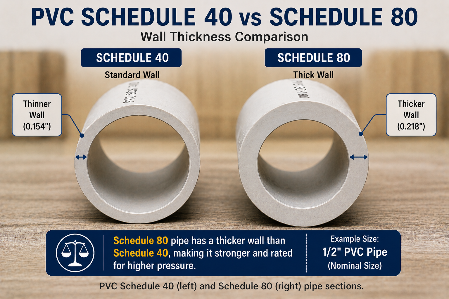
At the same NPS, Schedule 80 always uses more wall thickness, resulting in a smaller inside diameter, less flow area, and more material weight than Schedule 40. Schedule 160 continues that pattern with an even heavier wall and smaller bore.
⭐ STD, XS & XXS Pipe Wall Designations
These are alternative wall designations within ASME B36.10, not simply additional schedule numbers.
STD (Standard Weight)
For NPS 1/8 through 10, STD wall thickness matches Schedule 40. For NPS 12 and larger, STD uses a different (thinner relative) wall than Schedule 40 at that size, since Schedule 40’s thickness increases faster than STD at larger diameters.
XS (Extra Strong)
For NPS 1/8 through 8, XS wall thickness matches Schedule 80. For NPS 10 and larger, XS diverges from Schedule 80 and uses its own fixed wall thickness value.
XXS (Double Extra Strong)
A significantly heavier wall designation available only for a limited range of smaller to mid NPS sizes; it should not be treated as a universal “thicker version” available at every size, since XXS is not offered across the full NPS range.
| NPS | OD (in) | STD Wall | XS Wall | XXS Wall |
|---|---|---|---|---|
| 1/2 | 0.840 | 0.109 | 0.147 | 0.294 |
| 1 | 1.315 | 0.133 | 0.179 | 0.358 |
| 2 | 2.375 | 0.154 | 0.218 | 0.436 |
| 4 | 4.500 | 0.237 | 0.337 | 0.674 |
| 6 | 6.625 | 0.280 | 0.432 | 0.864 |
| 8 | 8.625 | 0.322 | 0.500 | 0.875 |
| 12 | 12.750 | 0.375 | 0.500 | — |
Notice XXS is not available beyond a limited size range in this common reference; always confirm actual availability for the specific NPS against the current ASME B36.10 table before specifying.
⭐⭐⭐ Stainless Steel Pipe: ASME B36.19
ASME B36.19 covers welded and seamless wrought stainless steel pipe using S schedule designations, kept as a separate table from carbon/alloy steel B36.10.
| NPS | OD (in) | Sch 10S Wall | Sch 40S Wall | Sch 80S Wall |
|---|---|---|---|---|
| 1/8 | 0.405 | 0.049 | 0.068 | 0.095 |
| 1/4 | 0.540 | 0.065 | 0.088 | 0.119 |
| 3/8 | 0.675 | 0.065 | 0.091 | 0.126 |
| 1/2 | 0.840 | 0.083 | 0.109 | 0.147 |
| 3/4 | 1.050 | 0.083 | 0.113 | 0.154 |
| 1 | 1.315 | 0.109 | 0.133 | 0.179 |
| 2 | 2.375 | 0.109 | 0.154 | 0.218 |
| 4 | 4.500 | 0.120 | 0.237 | 0.337 |
| 6 | 6.625 | 0.134 | 0.280 | 0.432 |
| 8 | 8.625 | 0.148 | 0.322 | 0.500 |
40S wall thickness matches Schedule 40 for NPS 1/8 through NPS 12, and 80S wall thickness matches Schedule 80 for NPS 1/8 through NPS 8. Beyond those ranges, and for certain 10S sizes, B36.19 values can differ from the equivalent B36.10 numbers, so always verify the specific size against the current standard.
⭐⭐⭐ ASME B36.10 vs B36.19
These are related but distinct standards, and their dimensions are not universally identical.
| Feature | ASME B36.10 | ASME B36.19 |
|---|---|---|
| Covers | Welded and seamless wrought carbon/alloy steel pipe | Welded and seamless wrought stainless steel pipe |
| Schedule labels | 5, 10, 20, 30, 40, 60, 80, 100, 120, 140, 160, STD, XS, XXS | 5S, 10S, 40S, 80S |
| Dimensional overlap | Baseline reference for most steel schedules | Generally matches B36.10 within stated size ranges, with noted exceptions |
ASME’s own documentation notes that wall thicknesses for certain sizes, including some Schedule 10S, 40S and 80S combinations at larger NPS, differ from the equivalent ANSI/ASME B36.10 values. Always confirm which standard applies to the actual material being specified, rather than assuming carbon steel and stainless steel dimensions are interchangeable at the same nominal schedule label.
⭐⭐⭐ PVC Pipe Wall Thickness: ASTM D1785
PVC pipe uses an entirely separate dimensional standard from steel; never mix these values into a steel schedule table.
| NPS | OD (in) | Sch 40 Min. Wall | Sch 80 Min. Wall | Sch 120 Min. Wall |
|---|---|---|---|---|
| 1/8 | 0.405 | 0.068 | 0.095 | — |
| 1/4 | 0.540 | 0.088 | 0.119 | — |
| 1/2 | 0.840 | 0.109 | 0.147 | 0.170 |
| 3/4 | 1.050 | 0.113 | 0.154 | 0.203 |
| 1 | 1.315 | 0.133 | 0.179 | 0.230 |
| 2 | 2.375 | 0.154 | 0.218 | 0.318 |
| 4 | 4.500 | 0.237 | 0.337 | 0.437 |
ASTM D1785 covers PVC Schedule 40, 80 and 120 pipe. Notice that PVC Schedule 40 and 80 wall thickness values happen to match the equivalent ASME B36.10 steel values at many common sizes, since PVC schedule dimensions were originally designed to align with steel pipe OD and schedule conventions, but the two standards remain governed separately and should be cited to their correct source.
CPVC pipe
Covered by ASTM F441, with dimensions that can differ from PVC despite sharing nominal size and schedule labels; always use the CPVC-specific table rather than assuming PVC dimensions apply.
ABS pipe
Uses its own applicable ASTM standard, such as ASTM D2661 for certain ABS Schedule 40 DWV pipe; do not mix ABS dimensions with PVC or steel schedule tables.
⭐⭐⭐ Pipe Material vs Dimensional Standard
Using the wrong standard for a given material is one of the most common and consequential pipe sizing errors.
| Material | Typical Dimension Standard |
|---|---|
| Carbon/alloy steel | ASME B36.10 |
| Stainless steel | ASME B36.19 |
| PVC | ASTM D1785 |
| CPVC | ASTM F441 |
| ABS | Applicable ASTM standard (varies by product, e.g. ASTM D2661 for some DWV pipe) |
| Copper tube | Type K/L/M systems (separate from NPS steel schedules) |
Copper tube is sized and thickness-rated using Type K, L, and M designations, which are entirely separate from NPS steel pipe schedules. Never apply a steel pipe schedule chart to copper tube.
⭐⭐⭐ Pipe Wall Thickness Calculation Formulas
These are geometric relationships, not pressure design equations.
| To Find | Formula |
|---|---|
| Wall thickness | t = (OD − ID) / 2 |
| Inside diameter | ID = OD − 2t |
| Outside diameter | OD = ID + 2t |
For a pipe with OD = 2.375 inches and ID = 2.067 inches: t = (2.375 minus 2.067) divided by 2 = 0.154 inches, matching the standard 2 inch NPS Schedule 40 value.
⭐⭐⭐ Pipe Wall Thickness and Pressure
Wall thickness is one input into pressure capability, not the sole determining factor.
Pressure capability depends on the applicable design code, material properties, design temperature, design pressure, weld or joint efficiency, corrosion allowance, and manufacturing tolerance, in addition to nominal wall thickness. Do not select a schedule based on wall thickness alone without completing the applicable pressure design calculation for the actual service conditions.
Design code requirements
Pressure piping design typically follows an applicable code (such as ASME B31 series piping codes) that defines the required calculation method, not simply a schedule lookup.
Corrosion allowance ⭐⭐⭐
Design thickness commonly includes an added corrosion allowance beyond the structurally required minimum, so that the pipe retains adequate strength as material is gradually lost to corrosion over its service life. Nominal wall thickness minus corrosion allowance approximates the structurally required design thickness.
⭐⭐⭐ Nominal vs Minimum Wall Thickness
These are related but distinct values that should never be treated as interchangeable.
| Term | Definition |
|---|---|
| Nominal wall thickness | The standardized dimension listed in the applicable specification table (such as the Schedule 40 value) |
| Minimum wall thickness | The minimum permissible thickness allowed under the applicable specification’s manufacturing tolerance, which can be somewhat less than nominal |
Actual measured wall thickness on a real pipe can differ from the nominal value due to normal manufacturing tolerance; this is why specifications define a minimum permissible thickness rather than requiring every point to measure exactly the nominal value.
⭐⭐⭐ Measuring Pipe Wall Thickness
Different situations call for different measurement tools.
Open pipe end
Measure OD and ID directly with a caliper, then calculate t = (OD minus ID) / 2.
Micrometer
Provides higher precision measurement than a standard caliper for critical verification work.
Ultrasonic thickness gauge ⭐⭐
Used for installed or closed piping where the wall cannot be measured directly with a caliper. A probe is coupled to the surface, calibrated for the specific material’s sound velocity, and used to measure thickness non-destructively. Surface condition, coating, and material properties all affect measurement accuracy.
Destructive cross-section
Cutting a sample for direct measurement, used in specific inspection or testing scenarios rather than routine field checks.
Inspection considerations ⭐⭐
Corrosion, erosion, pitting, and local thinning can all reduce measured wall thickness below the original nominal or minimum value at specific locations, particularly near welds or flow disturbances.
Pipe wall thickness loss
Thickness loss equals original or reference thickness minus current measured thickness. Evaluating whether remaining thickness is acceptable requires the applicable engineering or code criteria for that specific system, not a generic rule.
Pipe Wall Thickness, Flow Area & Weight
Changing schedule at a fixed NPS changes ID, which changes flow area and material weight.
Flow area
Internal flow area follows A = πD²/4 using the actual inside diameter. A thicker wall reduces ID and therefore reduces available flow area at the same nominal pipe size.
Weight
Greater wall thickness generally means more material per unit length, and therefore more weight per unit length, at the same OD and material. See the Pipe Weight Calculator for weight calculations by size and schedule.
| NPS 2 Schedule | ID (in) | Flow Area (in²) |
|---|---|---|
| Schedule 40 | 2.067 | 3.36 |
| Schedule 80 | 1.939 | 2.95 |
| Schedule 160 | 1.687 | 2.24 |
⭐⭐⭐ Pipe Wall Thickness by Common NPS
Quick reference across the most frequently searched sizes.
1/2 inch pipe ⭐
OD 0.840 in. Sch 40: 0.109 in wall, 0.622 in ID. Sch 80: 0.147 in wall, 0.546 in ID. Sch 160: 0.187 in wall, 0.466 in ID.
3/4 inch pipe
OD 1.050 in. Sch 40: 0.113 in wall, 0.824 in ID. Sch 80: 0.154 in wall, 0.742 in ID.
1 inch pipe
OD 1.315 in. Sch 40: 0.133 in wall, 1.049 in ID. Sch 80: 0.179 in wall, 0.957 in ID. Sch 160: 0.250 in wall, 0.815 in ID.
2 inch pipe ⭐
OD 2.375 in. Sch 40: 0.154 in wall, 2.067 in ID. Sch 80: 0.218 in wall, 1.939 in ID. Sch 160: 0.344 in wall, 1.687 in ID.
4 inch pipe ⭐
OD 4.500 in. Sch 40: 0.237 in wall, 4.026 in ID. Sch 80: 0.337 in wall, 3.826 in ID. Sch 160: 0.531 in wall, 3.438 in ID.
6 inch pipe
OD 6.625 in. Sch 40: 0.280 in wall, 6.065 in ID. Sch 80: 0.432 in wall, 5.761 in ID.
8 inch pipe
OD 8.625 in. Sch 40: 0.322 in wall, 7.981 in ID. Sch 80: 0.500 in wall, 7.625 in ID.
12 inch pipe
OD 12.750 in. Sch 40: 0.406 in wall, 11.938 in ID. Sch 80: 0.687 in wall, 11.376 in ID.
⭐ Pipe Wall Thickness Applications
Different applications call for different materials, standards, and schedule considerations.
Plumbing
Steel, PVC, CPVC, and copper each have their own dimensional standard; never mix schedule assumptions across materials.
Water lines
Material, schedule, nominal size, pressure requirements, temperature, and the applicable plumbing code together determine correct selection.
Industrial piping
Pressure, temperature, material, corrosion allowance, design code, and inspection requirements govern selection far beyond a simple schedule lookup.
Structural applications
Round HSS and structural pipe may use different dimensional and specification systems than pressure piping schedules; do not use a generic pipe schedule chart for structural design without confirming the applicable structural specification.
Construction ⭐
Water lines, pump systems, compressed air, concrete equipment, drainage, and temporary piping on construction sites commonly use steel or PVC schedule pipe; confirm material and standard before ordering fittings or replacement sections.

⭐⭐⭐ Pipe Wall Thickness Visual Guide
Original diagrams explaining pipe cross-section, schedule comparison, and NPS versus actual OD.
⭐⭐⭐ Pipe Wall Thickness Worked Examples
These examples demonstrate the core geometric relationships and schedule comparisons.
1. Calculate Wall Thickness
2. Calculate ID
3. Schedule 40 vs Schedule 80
4. Convert Thickness to mm
5. Stainless vs Carbon Steel
⭐⭐⭐ Common Pipe Wall Thickness Mistakes
Most pipe sizing errors trace back to one of these misunderstandings.
❌ Assuming NPS equals OD
Nominal pipe size and actual outside diameter are different values for NPS 12 and smaller.
❌ Assuming Schedule 40 means 0.040 inches
Schedule is a series designation, not a direct decimal thickness value.
❌ Assuming same schedule means same thickness at every size
Schedule 40 wall thickness varies significantly across different NPS values.
❌ Mixing steel and stainless schedules
B36.10 and B36.19 are related but not universally identical.
❌ Mixing PVC and steel tables
PVC follows ASTM D1785, a separate standard from ASME B36.10.
❌ Confusing nominal and minimum thickness
Manufacturing tolerance means actual measured thickness can be less than nominal.
❌ Ignoring manufacturing tolerance
Real pipe thickness varies within the specification’s allowed tolerance band.
❌ Using wall thickness alone for pressure design
Pressure capability depends on material, code, temperature, and other factors together.
❌ Assuming thicker wall always means higher pressure
Not necessarily true without the complete applicable design calculation.
❌ Ignoring corrosion allowance
Design thickness commonly includes an added allowance beyond structural minimum.
❌ Confusing pipe with tube
Pipe uses nominal sizing; tube is sized directly by actual outside diameter.
❌ Using a generic schedule chart for structural HSS
Structural round HSS may use a different specification system than pressure piping schedules.
Frequently Asked Questions
📄 Download Pipe Wall Thickness Chart PDF
This PDF is designed as a genuine field engineering reference. Use the print button to create a print-ready or downloadable version.
Cite or Embed This Chart
Copy the page-wide citation to reference the complete Pipe Wall Thickness Chart.