Stair Stringer Size Chart – Lumber Sizes, Throat Depth and Span
Stair Stringer Size ChartLumber Sizes, Throat Depth and Span
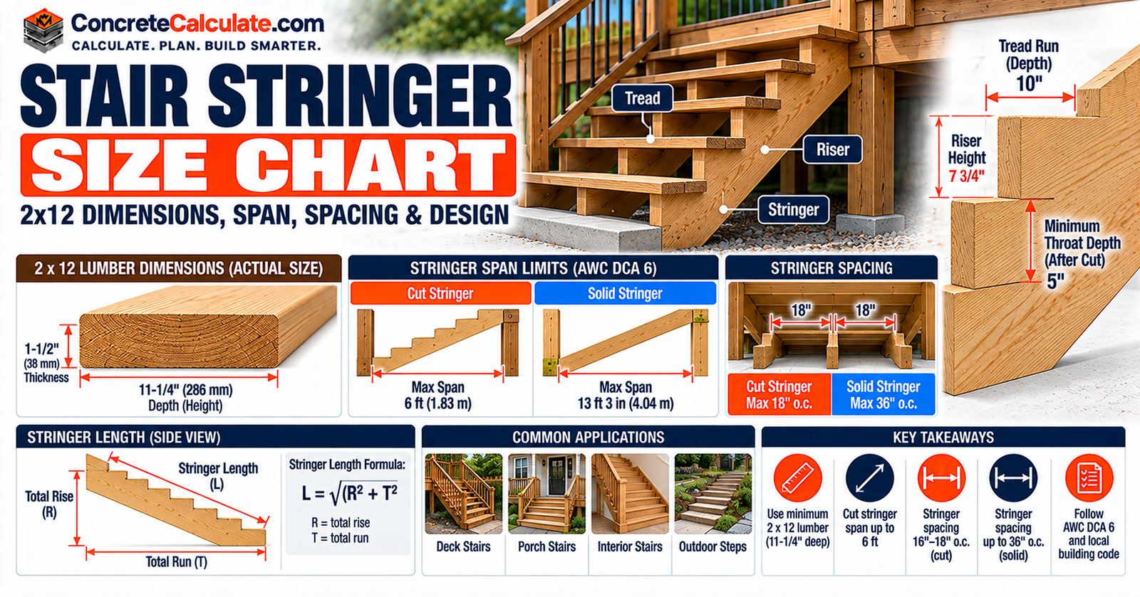
2 x 12 stringer dimensions, minimum throat depth, cut and solid stringer spans, spacing and counts, plus the geometry that sets stringer length.
 Reviewed by Muhammad Ramzan Babar, PhD Researcher (Plasma Physics) & Calculator Developer | View Profile
Quick Answer: Size, Throat, Span and Spacing Are Four Different Numbers
- AWC DCA 6 (2015 IRC basis) requires nominal 2 x 12 minimum stringers for its prescriptive deck stairs; actual depth is 11-1/4 in.
- Cut stringers need 5 in. minimum remaining throat, 6 ft maximum span and 18 in. o.c. maximum spacing. Solid stringers: 13 ft 3 in. span and 36 in. o.c. with the prescribed tread assembly.
- Stringer geometry length is not the structural span, and these limits are not rules for every stair.
Stair Stringer Size Chart
Lumber, throat depth, span and spacing for cut and solid stringers.
These values come from the American Wood Council’s DCA 6, Prescriptive Residential Wood Deck Construction Guide, based on the 2015 IRC. They apply to that guide’s covered deck stairs.
| Stringer configuration | Minimum nominal lumber | Common actual size | Required remaining throat | Maximum prescribed span | Maximum prescribed spacing |
|---|---|---|---|---|---|
| Cut wood stringer | 2 x 12 | 1-1/2 x 11-1/4 in. | 5 in. minimum | 6 ft | 18 in. o.c. |
| Solid wood stringer | 2 x 12 | 1-1/2 x 11-1/4 in. | Not applicable (no stair-step cutouts) | 13 ft 3 in. | 36 in. o.c., with the specified tread and ledger assembly |
How to read the chart
- The throat depth is measured after the notches are cut.
- The span limits describe support spacing, not purchased lumber length.
- Spacing depends on the prescribed tread and connection details. The 36 in. and 18 in. values are not interchangeable.
- Metric: 11-1/4 in. = 285.8 mm, 5 in. = 127 mm, 6 ft = 1.83 m, 13 ft 3 in. = 4.04 m.
Scope and source
DCA 6 also says that for stairs wider than 36 in., a combination of cut and solid stringers may be used at a maximum of 18 in. on center, and that at least three cut stringers are required if only cut stringers are used. Composite, PVC, engineered-wood, steel and proprietary stairs need their own design or manufacturer specification. Confirm the locally adopted code.
No 2 x 10 row on purpose
The researched prescriptive detail requires 2 x 12. A smaller cut stringer needs a separately justified design, not an invented span value.
What Size Lumber Should Stair Stringers Be?
Why the cited design uses 2 x 12.
In the cited DCA 6 design, every stringer is at least nominal 2 x 12. The extra depth is what leaves usable wood under the notches.
- Actual depth: 11-1/4 in., not 12 in.
- Cutout geometry: the notches remove wood from the top edge.
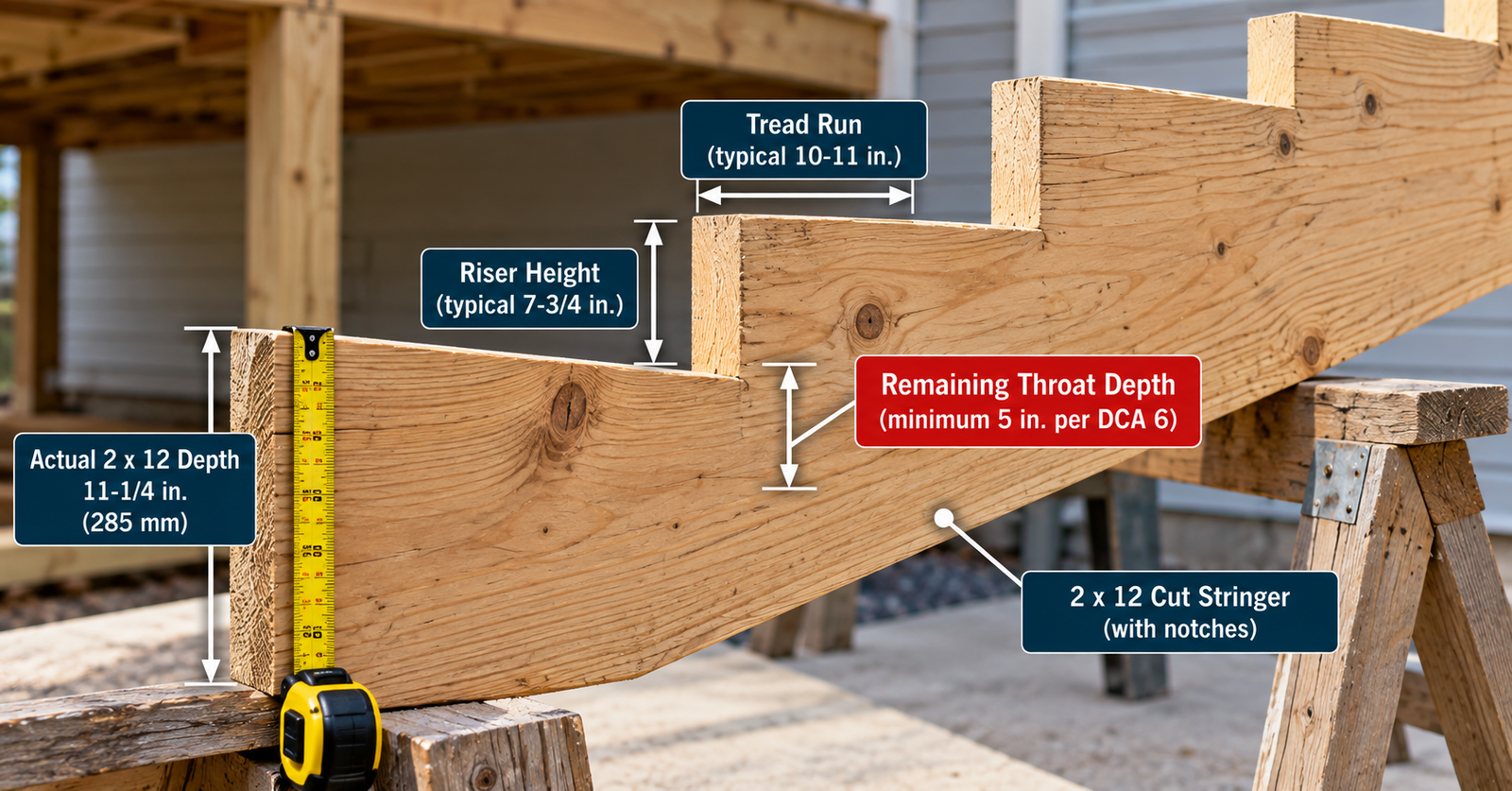
- Remaining section: at least 5 in. for the cut-stringer detail.
- Support span: 6 ft for cut and 13 ft 3 in. for solid.
- Species and grade: DCA 6 design values assume No. 2 grade and wet service.
- Treatment: exterior lumber is preservative treated or naturally durable, with cuts field treated.
Do not generalize the DCA 6 minimum to every staircase. Engineered, interior or commercial stairs follow other design rules.
Nominal vs. Actual Stair Stringer Dimensions
2 x 8, 2 x 10 and 2 x 12 compared.
Nominal sizes are trade names. Common surfaced lumber is smaller than its label.
| Nominal lumber | Actual thickness | Actual depth | Use in this chart |
|---|---|---|---|
| 2 x 8 | 1.50 in. | 7.25 in. | Dimensional comparison only |
| 2 x 10 | 1.50 in. | 9.25 in. | Dimensional comparison only |
| 2 x 12 | 1.50 in. | 11.25 in. | Minimum nominal size in the cited DCA 6 design |
The 2 x 8 and 2 x 10 rows are not approvals for cut stair stringers. Board depth alone does not establish adequacy after notching. See the Lumber Size Chart for the general explanation.
2 x 8 lumber
Actual size is about 1-1/2 x 7-1/4 in. (38 x 184 mm).
2 x 10 lumber
Actual size is about 1-1/2 x 9-1/4 in. (38 x 235 mm).
2 x 12 lumber
Actual size is about 1-1/2 x 11-1/4 in. (38 x 286 mm).
2 x 12 Stair Stringer Size and Requirements
What the cited design requires of the member.
The DCA 6 stair provisions place these requirements on a 2 x 12 stringer.
- Size: nominal 2 x 12 minimum, actual 1-1/2 x 11-1/4 in.
- Notching: cut stringers keep at least 5 in. of throat.
- Span: 6 ft for cut stringers and 13 ft 3 in. for solid stringers, shown in Figure 28 of the guide.
- Count: if only cut stringers are used, at least three.
- Connections: the top attaches with a sloped joist hanger, and the bottom bears on a supported end.
If a stringer would span more than the limit, DCA 6 allows a 4×4 post that is notched and bolted with two 1/2 in. through-bolts, or an intermediate landing.
Can You Use a 2 x 10 for Stair Stringers?
Layout fit is not structural approval.
The cited DCA 6 design requires a minimum nominal 2 x 12. A 2 x 10 is not approved just because the layout appears to fit in its depth.
| Nominal lumber | Actual depth | Notch depth | Remaining throat | Meets 5 in.? |
|---|---|---|---|---|
| 2 x 8 | 7.25 in. | 6.13 in. | 1.12 in. | No |
| 2 x 10 | 9.25 in. | 6.13 in. | 3.12 in. | No |
| 2 x 12 | 11.25 in. | 6.13 in. | 5.12 in. | Yes |
Geometric illustration only, using the idealized notch model in the throat-depth section. It is not a structural check.
Three different situations
- Conventional prescriptive deck stair: DCA 6 requires 2 x 12.
- Independently engineered stair: a design professional can justify other members.
- Proprietary manufactured system: follow the manufacturer’s design documents.
Cut vs. Solid Stair Stringers
Two constructions with different limits.
| Feature | Cut stringer | Solid stringer |
|---|---|---|
| Basic configuration | Stair-step notches cut into the member | Continuous-depth member with separate tread supports |
| AWC DCA 6 minimum member | 2 x 12 | 2 x 12 |
| Remaining throat | 5 in. minimum | No comparable stair-step throat cut |
| Prescribed maximum span | 6 ft | 13 ft 3 in. |
| Prescribed maximum spacing | 18 in. o.c. | 36 in. o.c. |
| Tread support | Notched horizontal seats | Prescribed ledgers or support system |
| Key limitation | Reduced effective section at notches | Tread and ledger assembly must meet prescribed details |
Cut stringers
The notched stair profile. The notches create the treads but reduce the effective section.
Solid stringers
An unnotched member with treads carried on separately attached supports.
An unnotched 2 x 12 does not automatically qualify as a 13 ft 3 in. stair stringer. The tread and ledger assembly and end supports must meet the prescribed details.
Stair Stringer Throat Depth Chart
Remaining wood under the notches.
What is throat depth?
The shortest effective distance between the bottom of a notch and the opposite edge of the stringer.
How to measure remaining depth
Measure perpendicular to the uncut lower edge at the controlling notch, not straight down.
Why excessive notching matters
Cutouts reduce the member’s effective section. Saw cuts that run past the inside corners weaken it further.
| Unit rise | Unit run | Notch depth (in.) | Remaining throat (in.) | Versus 5 in. minimum |
|---|---|---|---|---|
| 7 in. | 10 in. | 5.74 | 5.52 | Above |
| 7-1/2 in. | 10 in. | 6.00 | 5.25 | Above |
| 7-3/4 in. | 10 in. | 6.13 | 5.12 | Above |
| 7 in. | 11 in. | 5.91 | 5.34 | Above |
| 7-3/4 in. | 11 in. | 6.34 | 4.91 | Below |
Idealized geometry for a straight-sided 2 x 12. It does not include saw overcuts, defects, end connections or unusual geometry. A throat below 5 in. falls outside the cited prescriptive detail and needs a redesign or an engineered check.
Figure 1. A notched 2 x 12 with the 5 in. minimum throat measured perpendicular to the uncut lower edge.
How Stair Rise and Run Affect Throat Depth
The notch formula and a worked 7-3/4 in. example.
Larger rise or run deepens the notch measured across the sloping board, so less wood remains.
Idealized notch geometry
- D = actual board depth (11.25 in. for a 2 x 12)
- r = unit rise, g = horizontal notch run
- dnotch = notch depth measured perpendicular to the sloped edge
7-3/4 in. Rise and 10 in. Run
What it means: This agrees with the roughly 5.1 in. depth AWC discusses in the DCA 6 commentary for a 7.75:10 rise-to-run ratio.
A model, not a verification
The formula is an idealized right-angle notch in a straight-sided board. It does not replace inspecting the actual stringer or complying with the governing design.
Stair Stringer Span Chart
Cut and solid stringer support spans.
The span is the horizontal distance between the supports shown in the guide. AWC analyzes solid stringers as simple-span beams using the horizontal span, not the actual stringer length.
| Stringer type | Nominal lumber | Maximum prescribed span |
|---|---|---|
| Cut stringer | 2 x 12 | 6 ft |
| Solid stringer | 2 x 12 | 13 ft 3 in. |
Cut stringer maximum span
The 6 ft limit reflects the notched section, remaining throat, support conditions, loading and connections. A 2 x 12 cut stringer is not good for 6 ft under every condition.
Solid stringer maximum span
The 13 ft 3 in. limit applies to the prescribed solid-stringer assembly: continuous member depth, tread ledgers, tread species and size, supports and connections.
Structural span versus board length
The span chart does not set the purchased board length, and it is not permission to build any 13 ft 3 in. stair without checking loads, connections and support geometry. Add an intermediate post or landing for a longer flight.
Figure 2. Cut and solid stringer span limits. The same stair is drawn twice; the limits belong to the AWC DCA 6 assemblies.
Stair Stringer Spacing Chart
Spacing values and the assemblies they belong to.
Four things are easy to confuse: stringer spacing, stair width, tread span and structural stringer span.
- Cut stringers: 18 in. o.c. maximum for the specified cut-stringer and tread assembly (2 x 4 or 5/4 treads).
- Solid stringers: 36 in. o.c. maximum for the prescribed solid-stringer, tread and ledger assembly.
- Wider stairs: DCA 6 allows a combination of cut and solid stringers at 18 in. o.c. maximum for stairs wider than 36 in.
These spacing values are not interchangeable. The Deck Post Spacing Chart covers support posts for the deck, not stringer spacing.
How Many Stair Stringers Do You Need?
The count formula and 36, 42 and 48 inch examples.
Stringer count
- W = distance between outer stringer centerlines (in.)
- Smax = permitted maximum on-center spacing (in.)
- N = preliminary number of stringers
| Outer stringer centerline distance | Preliminary count | Actual uniform spacing |
|---|---|---|
| 36 in. | 3 | 18 in. |
| 42 in. | 4 | 14 in. |
| 48 in. | 4 | 16 in. |
| 60 in. | 5 | 15 in. |
| 72 in. | 5 | 18 in. |
The first column is the distance between outer stringer centerlines, not automatically the finished stair width. The formula assumes a straight flight and uniform layout and is a layout aid, not a structural design. DCA 6 requires at least three cut stringers.
Stringers for 36-, 42- and 48-inch layouts
- 36 in. example: three stringers at 18 in.
- 42 in. example: four stringers at 14 in.
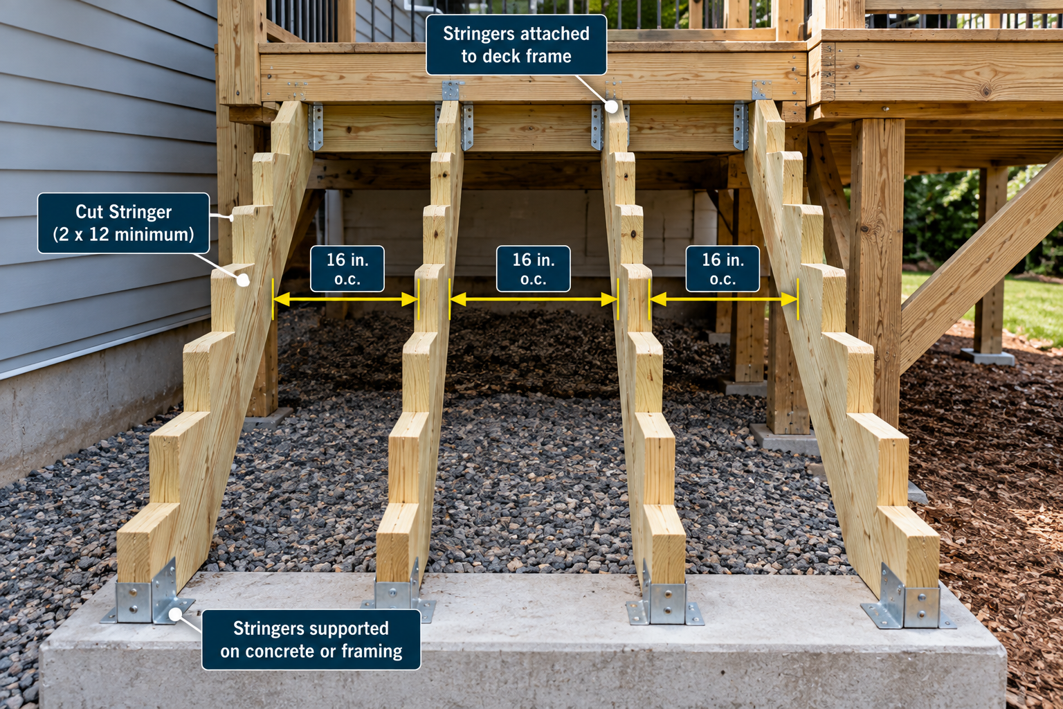
- 48 in. example: four stringers at 16 in.
Figure 3. Four stringers at 16 in. on center across a 48 in. outer centerline distance.
Stair Stringer Spacing for Wood and Composite Treads
Tread material changes the layout.
Wood tread size requirements
| Wood species group | Cut-stringer tread | Solid-stringer tread |
|---|---|---|
| Southern Pine | 2 x 4 or 5/4 | 2 x 8 |
| Douglas Fir-Larch, Hem-Fir, SPF | 2 x 4 or 5/4 | 2 x 8 or 3 x 4 |
| Redwood, Western Cedars, Ponderosa Pine, Red Pine | 2 x 4 or 5/4 | 2 x 10 or 3 x 4 |
Assumes a 300 lb concentrated load, L/288 deflection limit, No. 2 grade and wet service conditions. These are member sizes for the specified tread configurations, not necessarily the finished tread depth; a tread can be built from more than one board.
Composite tread support requirements
Composite and PVC stair treads must follow the exact manufacturer’s stair-tread support and fastening requirements. Do not apply the 18 in. wood-tread allowance to a composite product.
- Use the exact product and its current installation guide.
- Check stair-tread approval, maximum support spacing, fastening and nosing.
- Scalloped and solid profiles can differ.
If a product requires 12 in. maximum spacing, recalculate with 12 in. (see the table below). For decking dimensions see the Deck Board Size Chart, and for decking quantities use the Decking Calculator.
| Outer stringer centerline distance | Count at 12 in. maximum |
|---|---|
| 36 in. | 4 |
| 42 in. | 5 |
| 48 in. | 5 |
| 60 in. | 6 |
| 72 in. | 7 |
Stair Stringer Rise and Run Dimensions
IRC limits and the terms used on this page.
Five terms drive the stringer layout.
- Total rise: finished floor to finished floor.
- Unit rise: one riser height.
- Total run: horizontal distance of the flight.
- Unit run: horizontal depth of one step.
- Number of risers and runs: runs = risers – 1 in a simple straight flight.
| Item | Reference value |
|---|---|
| Maximum riser height | 7-3/4 in. |
| Minimum tread depth | 10 in. |
| Maximum riser-height variation in a flight | 3/8 in. |
| Maximum tread-depth variation in a flight | 3/8 in. |
Local code adoption and exceptions apply. The 10 in. tread depth is not automatically the horizontal notch run used on the stringer, because nosing and tread construction affect the finished geometry.
The full rise and run method belongs in the Stair Rise and Run Chart; this page only shows how those numbers affect the stringer.
Equipment for Your Project
Affiliate disclosure: As an Amazon Associate, ConcreteCalculate earns from qualifying purchases. We may also earn a commission from other affiliate links at no additional cost to you.
How to Calculate Stair Stringer Length
Total rise, total run and the diagonal.
Geometric diagonal
- N = number of risers, r = unit rise, g = unit horizontal run
- H = total rise, R = total horizontal run, L = geometric diagonal
Seven-Riser Stair
What it means: This is the theoretical diagonal. A 6 ft 6 in. blank will not necessarily accommodate the full uncut profile, end details and cutting allowance.
For an interactive version, use the Stair Calculator.
Figure 4. Seven risers, six runs, total rise 49 in., total run 60 in. and a 77.5 in. diagonal.
Stair Stringer Length Chart by Number of Steps
Geometric diagonals for a 7 x 10 stair.
| Risers | Total rise | Runs | Total horizontal run | Geometric diagonal |
|---|---|---|---|---|
| 4 | 28 in. | 3 | 30 in. | 41.0 in. |
| 5 | 35 in. | 4 | 40 in. | 53.2 in. |
| 6 | 42 in. | 5 | 50 in. | 65.3 in. |
| 7 | 49 in. | 6 | 60 in. | 77.5 in. |
| 8 | 56 in. | 7 | 70 in. | 89.6 in. |
| 9 | 63 in. | 8 | 80 in. | 101.8 in. |
| 10 | 70 in. | 9 | 90 in. | 114.0 in. |
Assumes 7 in. risers, 10 in. runs, one fewer run than risers, a straight flight, the upper finished floor as the final surface, and no intermediate landing. These are geometric values, not allowable spans, and not stock-board lengths.
How to Choose a Stair Stringer Board Length
Why the diagonal is not the purchase length.
A stringer blank must cover more than the diagonal. Consider these.
- Total geometry (rise and run).
- Top connection and bottom bearing details.
- End-cut requirements and a cutting margin.
- Lumber quality and defects.
- Transport and handling.
Do not buy a board by rounding the diagonal up to the next stock length. Use the Lumber Calculator for quantities after the layout is drawn.
Stair Stringer Layout and Cutting Dimensions
Framing-square layout and notch discipline.
Layout is repetition: mark the unit rise and run with a framing square, repeat the step positions, then establish the top plumb cut and bottom seat.
- Account for the finished tread thickness and the landing elevations.
- Keep saw cuts at the inside notch corners; overcuts beyond the corners weaken a cut stringer.
- Check the remaining throat at the controlling notch before cutting the others.
This page is a size reference, not a step-by-step stair construction guide.
Bottom Riser Adjustment for Tread Thickness
Keeping finished risers equal.
When treads sit on top of the notches, the first riser may need an adjustment so every finished riser is the same.
Illustrative Bottom Riser
What it means: Do not universally remove exactly 1 in. The adjustment depends on tread thickness, top connection, landing height, finished-floor buildup and stair geometry.
Measure risers from finished surface to finished surface. IRC limits the variation in riser height within a flight to 3/8 in.
Stair Stringer Top Connection Requirements
Hangers, framing and load transfer.
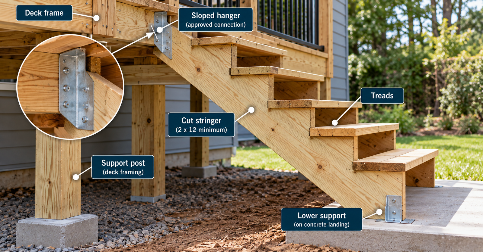
Selecting a lumber size does not finish the design. The upper end must transfer loads to a supporting rim or header.
- DCA 6 Figure 31 shows a sloped joist hanger with a minimum vertical (download) capacity of 625 lb for the illustrated attachment.
- Use fasteners and connectors that are corrosion resistant (hot-dip galvanized or stainless steel) for treated lumber.
- Blocking and the supporting member must carry the load.
That 625 lb value belongs to that detail; it is not a universal connector requirement.
Stair Stringer Bottom Support and Footings
Bearing at grade.
Stringers should be supported by bearing at the end where the stair meets grade.
- DCA 6 attaches the stringers to the stair guard posts at the bottom, with posts bearing on footings.
- A 2×4 bearing block helps avoid splitting at the stringer end, especially for cut stringers.
- The default stair footing in the guide assumes a 40 psf live load and 10 psf dead load over an 18 in. width and half of the 13 ft 3 in. solid span, about 500 lb.
- Moisture, settlement and anchorage matter; an unstable landing can invalidate suitable member dimensions.
Intermediate Stair Stringer Supports
Posts and landings that shorten the span.
When the span exceeds the limit, shorten it with intermediate support.
- DCA 6 allows a 4×4 post, notched and bolted to the stringer with two 1/2 in. through-bolts with washers.
- The post is centered on a 12 in. diameter or 10 in. square, 6 in. thick footing.
- An intermediate landing may also shorten the span; if total stair height exceeds 12 ft, an intermediate landing is required and must be built as a non-ledger deck.
An arbitrary block under a stringer does not make a compliant support. For general post sizes see the Deck Post Size Chart.
Interior vs. Exterior Stair Stringer Sizes
Different design conditions.
Interior stairs
Dry-service conditions, finished assemblies and engineered framing are common. Architectural constraints and the adopted code drive the design.
Exterior deck stairs
Wet-service conditions apply. DCA 6 requires naturally durable or preservative-treated lumber (above-ground and ground-contact use categories), field treatment of cuts, and corrosion-resistant fasteners and connectors.
The DCA 6 chart is specifically relevant to its single-level residential wood-deck scope, not to every stair.
Engineered Wood and Steel Stair Stringers
Outside the 2 x 12 chart.
LVL and other engineered-wood stringers, steel channel stringers, fabricated steel plate stringers and proprietary stair systems cannot be sized from the 2 x 12 wood chart.
- Require manufacturer design documentation or project-specific structural design.
- Do not infer a universal LVL or steel size.
Stair Stringer Size vs. Stair Width
Width changes the count, not the span.
Stair width, stringer depth and stringer spacing are different things.
- Member depth: the lumber and its remaining throat.
- Stringer spacing: on-center layout.
- Finished and clear stair width: what users walk on.
- Tread projection: how far treads extend past the outer stringers.
For a 36 in. stair, DCA 6 requires at least three cut stringers. A wider stair usually needs more stringers or closer spacing, but that does not by itself change the allowable longitudinal span.
Common Stair Stringer Sizing Mistakes
Errors that make stringers fail inspection.
Assuming 2 x 12 is 12 in. deep
The actual depth is 11-1/4 in.
Using a 2 x 10 without verifying the design
Layout fit is not approval.
Cutting below the prescribed throat
Keep at least 5 in. for the cited detail.
Overcutting past notch corners
It weakens the stringer.
Confusing span with board length
They are different numbers.
Confusing spacing with tread depth
Spacing is on center.
Mixing cut and solid span limits
6 ft versus 13 ft 3 in.
Mixing cut and solid spacing
18 in. versus 36 in.
Assuming composite follows wood-tread rules
Check the product.
Ignoring tread species and grade
Table 6 depends on species.
Using the diagonal as structural approval
It is geometry only.
Forgetting the finished floor
Measure finished to finished.
Ignoring tread thickness at the bottom
The first riser may change.
Omitting top connection details
Hangers and blocking matter.
Setting stringers on unstable ground
Bearing must be stable.
Adding unengineered intermediate supports
Use the prescribed post and footing.
Using untreated exterior lumber
Treat or use durable species.
Assuming DCA 6 covers every stair
It is limited to its scope.
More framing references are in the Construction Charts hub.
Stair Stringer Size FAQs
Short answers to common stair stringer questions.
AWC DCA 6 requires nominal 2 x 12 minimum stringers for its prescriptive residential wood-deck stairs. Other approved or engineered stair systems may use different members.
Yes within the DCA 6 prescriptive design, where all stringers must be at least nominal 2 x 12. A different member needs a separately justified design or an approved system.
Not under the DCA 6 prescriptive design. A 2 x 10 is 9-1/4 in. deep, and a typical 7-3/4 x 10 notch would leave only about 3.1 in., below the 5 in. throat required there.
About 11-1/4 in. (285.8 mm), with a thickness of about 1-1/2 in.
The cited DCA 6 cut-stringer detail requires at least 5 in. of remaining depth, measured perpendicular to the uncut lower edge.
The cited DCA 6 design limits the horizontal support span of a cut stringer to 6 ft. This is not a universal span for every stair assembly.
The cited DCA 6 design allows 13 ft 3 in. for a solid stringer in the prescribed assembly with its tread and ledger details.
In the cited AWC details, cut stringers are up to 18 in. on center and solid stringers up to 36 in. on center with the specified tread and ledger assembly. Proprietary treads can require different spacing.
With cut stringers at 18 in. maximum spacing, three (DCA 6 also requires at least three cut stringers). That assumes a 36 in. distance between outer stringer centerlines.
Four at 14 in. spacing, using the preliminary formula N = ceil(W / S) + 1 with an 18 in. maximum and a 42 in. outer centerline distance.
Four at 16 in. spacing for a 48 in. outer centerline distance under an 18 in. maximum.
Often, but it depends on the product. Use the manufacturer’s stair-tread support and fastening requirements; if one requires 12 in. maximum spacing, a 48 in. layout needs five stringers.
A cut stringer has stair-step notches in the member, which reduces its section. A solid stringer is unnotched and carries separately supported treads.
Use the geometric diagonal L = sqrt(H^2 + R^2) with total rise H and total horizontal run R. For 49 in. of rise and 60 in. of run, L is about 77.5 in. Then account for the actual profile, end details, supports and cutting allowance.
No. The diagonal is a geometric length. The structural span is the horizontal distance between supports, with the limits shown in the guide.
At least 5 in. for the cited DCA 6 cut-stringer detail, measured perpendicular to the uncut lower edge. A smaller remainder falls outside the prescriptive detail.
Divide the total rise by a target unit rise and round to a whole number, then divide the total rise by that number. Keep each riser at or below 7-3/4 in. under the 2021 IRC and within 3/8 in. of the others.
Exterior wood stringers must be preservative treated or a naturally durable species. DCA 6 also calls for field treatment of cuts and corrosion-resistant fasteners.
Engineered wood stringers are possible, but their size and span cannot be taken from the 2 x 12 wood chart. Use the manufacturer’s design documents or a project-specific design.
When its span exceeds the prescribed limit or the stair is tall. DCA 6 allows a notched and bolted 4×4 post on a footing or an intermediate landing, and requires a landing if total vertical height exceeds 12 ft.
Print This Stair Stringer Size Chart
Use your browser to save this page as a PDF for a job-site binder or estimating folder. Interactive sections are hidden when printing.