U Bolt Size Chart – Dimensions, Pipe Sizes and Thread Sizes
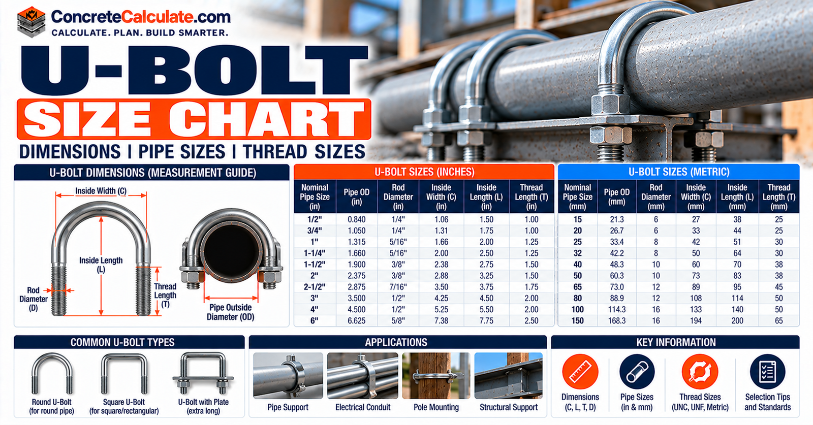
U Bolt Size Chart
Dimensions, Pipe Sizes and Thread Sizes
Learn what rod diameter, inside width, inside length and thread length mean, see a manufacturer pipe U-bolt chart, and follow the path from nominal pipe size to actual pipe OD to the U-bolt that fits.
 Reviewed by Muhammad Ramzan Babar, PhD Researcher (Plasma Physics) & Calculator Developer – View Profile
Short Answer
A U-bolt is described by at least four dimensions: rod diameter D, inside width C, inside length L and thread length T, plus thread pitch and bend style. Pipe U-bolts are sold by nominal pipe size, but the fit depends on the actual pipe OD: nominal 2 in. pipe measures 2.375 in. and the Fastenal U-bolt for it has a 2-1/2 in. inside width. Dimensions vary by manufacturer, so read the product drawing.
U-Bolt Size Chart
Start with the four dimensions that define a U-bolt: rod diameter, inside width, inside length and thread length. The chart shows one manufacturer’s pipe U-bolt dimensions, and the sections below explain how to use them.
How to Read the Chart
D is the rod and thread diameter, C is the inside width between the legs, L is the inside length and T is the reference thread length. The pipe-size column is the product’s pipe designation, and C is not the pipe’s actual outside diameter. Dimensions are in inches.
Common U-Bolt Dimensions
| Nominal Pipe Size | Rod Diameter D | Inside Width C | Inside Length L | Thread Length T (ref.) |
|---|---|---|---|---|
| 1/2″ | 3/8″ | 1″ | 2-1/4″ | 1-1/4″ |
| 3/4″ | 3/8″ | 1-1/4″ | 2-1/4″ | 1-1/4″ |
| 1″ | 3/8″ | 1-1/2″ | 2-1/2″ | 1-1/4″ |
| 1-1/4″ | 3/8″ | 1-3/4″ | 2-3/4″ | 1-1/8″ |
| 1-1/2″ | 3/8″ | 2″ | 2-5/8″ | 1-1/4″ |
| 2″ | 3/8″ | 2-1/2″ | 3-1/8″ | 1-1/4″ |
| 2-1/2″ | 3/8″ | 3″ | 3-5/8″ | 1-1/4″ |
| 3″ | 3/8″ | 3-1/2″ | 4-1/8″ | 1-1/4″ |
| 3-1/2″ | 3/8″ | 4″ | 5-1/2″ | 2-1/4″ |
| 4″ | 3/8″ | 4-1/2″ | 6″ | 2-1/4″ |
| 6″ | 1/2″ | 6-3/4″ | 8-3/8″ | 2″ |
| 8″ | 1/2″ | 8-3/4″ | 10-3/8″ | 2″ |
These are specific commercial product dimensions, not universal ASME dimensions for every U-bolt. Verify the selected manufacturer’s drawing. Fastenal lists several rod sizes for some pipe sizes; this table shows the 3/8 in. rod through 4 in. and the 1/2 in. rod for 6 and 8 in. The full list is in the rod diameter section below.
Source: Fastenal Product Standard UBOLT.Z Rev. 07 (February 2, 2024)A “2-Inch U-Bolt” Can Mean Different Things
A seller may be describing nominal pipe size, inside width or another product designation. Always inspect the dimension drawing. For a 2-in. pipe, the Fastenal U-bolt has an inside width of 2-1/2 in.
How to Read U-Bolt Dimensions
Rod Diameter
D is the diameter of the steel rod and usually the nominal thread diameter.
Inside Width
C is the clear distance between the two legs, measured between the inner faces.
Inside Length
L is the inside dimension from the bend toward the leg ends, following the manufacturer’s stated reference.
Thread Length
T is the length of the usable threaded leg. Fastenal lists it as a reference value.
| Symbol | Dimension | Meaning |
|---|---|---|
| D | Rod diameter | Diameter of the U-bolt stock and thread |
| C | Inside width | Clear width between the legs |
| L | Inside length | Inside distance from the bend to the end reference used by the product |
| T | Thread length | Length of the threaded portion |
| OD | Outside diameter | Actual outside diameter of the pipe or object being clamped |
How to Measure a U-Bolt
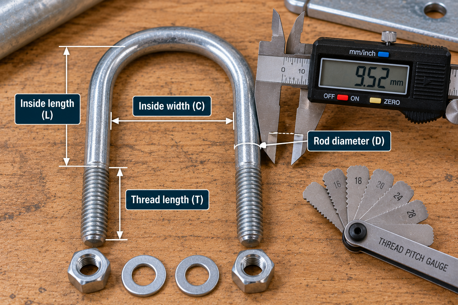
- Measure the rod diameter D across one leg.
- Measure the clear inside width C between the inner leg faces.
- Measure the inside length L from the inside bend reference to the leg-end reference.
- Measure the threaded length T.
- Determine the thread pitch with a thread gauge. The Thread Identification Chart helps.
- Identify the bend style, round or square.
- Identify the coating and material where relevant.
Do Not Identify a Replacement from Outside Width Alone
Do not measure only the outside-to-outside width and call that the nominal size. Overall and inside length conventions can differ, so check how the supplier defines L on its drawing.
Pipe U-Bolt Size Chart
Pipe U-bolts are often sold by nominal pipe size, but fit depends on the actual pipe outside diameter and the U-bolt’s manufactured inside width. The table below lists the sizes with every dimension, with the pipe’s actual OD for comparison. For the full pipe OD reference, see the Pipe Outside Diameter Chart.
| Nominal Pipe Size | Rod D | Pipe OD (in.) | Inside Width C (in.) | C minus OD (in.) | Listed Tolerance (in.) |
|---|---|---|---|---|---|
| 1/2″ | 3/8″ | 0.840 | 1.000 | +0.160 | ±.059 |
| 3/4″ | 3/8″ | 1.050 | 1.250 | +0.200 | ±.059 |
| 1″ | 3/8″ | 1.315 | 1.500 | +0.185 | ±.059 |
| 1-1/4″ | 3/8″ | 1.660 | 1.750 | +0.090 | ±.059 |
| 1-1/2″ | 3/8″ | 1.900 | 2.000 | +0.100 | ±.059 |
| 2″ | 3/8″ | 2.375 | 2.500 | +0.125 | ±.059 |
| 2-1/2″ | 3/8″ | 2.875 | 3.000 | +0.125 | ±.059 |
| 3″ | 3/8″ | 3.500 | 3.500 | +0.000 | ±.059 |
| 3-1/2″ | 3/8″ | 4.000 | 4.000 | +0.000 | ±.059 |
| 4″ | 3/8″ | 4.500 | 4.500 | +0.000 | ±.059 |
| 6″ | 1/2″ | 6.625 | 6.750 | +0.125 | ±.118 |
| 8″ | 1/2″ | 8.625 | 8.750 | +0.125 | ±.157 |
For 3, 3-1/2 and 4 in. pipe, the Fastenal inside width equals the pipe OD, within the listed tolerance. A rule that C must be larger than the pipe does not hold for every product, so rely on the manufacturer’s drawing and tolerance.
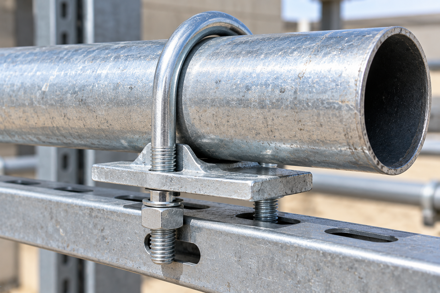
Nominal Pipe Size vs. Actual Pipe OD
Nominal pipe size is a naming system, not a direct measurement of OD. In the Fastenal series, a U-bolt sold for 2-in. pipe has an inside width of 2-1/2 in., while the 2-in. pipe OD is 2.375 in. Do not conclude that every 2-in. pipe U-bolt measures 2-1/2 in. internally. Pipe wall and schedule are in the Pipe Schedule Chart.
U-Bolt Inside Width
The inside width must accommodate the actual OD or width of the object, product-specific clearance, any coating or liner, and manufacturing tolerance. In a basic fit sense C must be at least the pipe OD, but do not invent a universal clearance value. Across the full Fastenal list, C minus OD ranges from 0.000 to 0.200 in. Manufacturer dimensions govern.
U-Bolt Inside Length
The inside length must be long enough for the object height or diameter, any saddle or mounting plate, washers, nuts, the required thread engagement and installation clearance. Do not use a universal rule such as pipe diameter plus a fixed number of inches. Check how the manufacturer defines L.
U-Bolt Thread Length
Distinguish the overall leg length, the threaded portion and the unthreaded tangent. The selected U-bolt must leave usable thread after every clamped component is assembled. Fastenal lists thread length as a reference value, for example 1-1/4 in. on most 3/8 in. rod pipe sizes and 2 in. on its 6 and 8 in. pipe U-bolts.
U-Bolt Rod Diameter Chart
Common rod diameters and their UNC thread designations are below. These are common coarse threads, not a statement that every U-bolt of that diameter must use UNC. Rod diameter alone does not establish load capacity. For bolt diameters generally see the Bolt Diameter Chart.
| Nominal Rod Diameter (in.) | Decimal (in.) | Millimeters | Common UNC Thread |
|---|---|---|---|
| 1/4 | 0.2500 | 6.350 | 1/4-20 |
| 5/16 | 0.3125 | 7.938 | 5/16-18 |
| 3/8 | 0.3750 | 9.525 | 3/8-16 |
| 7/16 | 0.4375 | 11.112 | 7/16-14 |
| 1/2 | 0.5000 | 12.700 | 1/2-13 |
| 5/8 | 0.6250 | 15.875 | 5/8-11 |
| 3/4 | 0.7500 | 19.050 | 3/4-10 |
| 7/8 | 0.8750 | 22.225 | 7/8-9 |
| 1 | 1.0000 | 25.400 | 1-8 |
Complete Fastenal UBOLT.Z Dimension List
| Part No. | Rod D | Pipe Size | Inside Width C | Inside Length L | Thread Length T (ref.) | Tolerance |
|---|---|---|---|---|---|---|
| 42000 | 1/4″ | 1/4″ | 9/16″ | 1-1/4″ | 3/4″ | ±.039 |
| 42002 | 1/4″ | 3/8″ | 3/4″ | 1-1/4″ | 5/8″ | ±.039 |
| 42003 | 1/4″ | 3/8″ | 3/4″ | 2-1/4″ | 1-1/2″ | ±.039 |
| 42004 | 1/4″ | 1/2″ | 1″ | 1-3/4″ | 1″ | ±.039 |
| 42010 | 1/4″ | 3/4″ | 1-1/8″ | 2″ | 1″ | ±.039 |
| 42005 | 1/4″ | 1/2″ | 1″ | 2-3/4″ | 1-1/4″ | ±.039 |
| 42011 | 1/4″ | 3/4″ | 1-1/8″ | 3-1/8″ | 1-1/2″ | ±.039 |
| 42001 | 1/4″ | 3/4″ | 1-1/4″ | 2-1/4″ | 1-1/4″ | ±.039 |
| 42016 | 1/4″ | 1″ | 1-1/2″ | 2-3/4″ | 1-3/8″ | ±.039 |
| 42017 | 1/4″ | 1″ | 1-3/8″ | 3-7/16″ | 2-3/8″ | ±.039 |
| 42022 | 1/4″ | 1-1/4″ | 1-3/4″ | 3″ | 1-3/8″ | ±.039 |
| 42028 | 1/4″ | 1-1/2″ | 2″ | 3-1/4″ | 1-3/8″ | ±.039 |
| 42006 | 5/16″ | 1/2″ | 1″ | 2-3/16″ | 1-3/8″ | ±.039 |
| 42012 | 5/16″ | 3/4″ | 1-1/8″ | 2-3/16″ | 1″ | ±.039 |
| 42018 | 5/16″ | 1″ | 1-3/8″ | 2-3/16″ | 1″ | ±.039 |
| 42024 | 5/16″ | 1-1/4″ | 1-3/4″ | 2-11/16″ | 1-1/8″ | ±.039 |
| 42025 | 5/16″ | 1-1/4″ | 1-3/4″ | 4-1/2″ | 2″ | ±.039 |
| 42030 | 5/16″ | 1-1/2″ | 2″ | 2-11/16″ | 1″ | ±.059 |
| 42031 | 5/16″ | 1-1/2″ | 2″ | 4-3/4″ | 3″ | ±.059 |
| 42034 | 5/16″ | 2″ | 2-1/2″ | 3-3/16″ | 1″ | ±.059 |
| 42035 | 5/16″ | 2″ | 2-1/2″ | 5-5/8″ | 3″ | ±.059 |
| 42038 | 5/16″ | 2-1/2″ | 3″ | 3-11/16″ | 1″ | ±.059 |
| 42008 | 3/8″ | 1/2″ | 1″ | 2-1/4″ | 1-1/4″ | ±.059 |
| 42014 | 3/8″ | 3/4″ | 1-1/4″ | 2-1/4″ | 1-1/4″ | ±.059 |
| 42020 | 3/8″ | 1″ | 1-1/2″ | 2-1/2″ | 1-1/4″ | ±.059 |
| 42026 | 3/8″ | 1-1/4″ | 1-3/4″ | 2-3/4″ | 1-1/8″ | ±.059 |
| 42032 | 3/8″ | 1-1/2″ | 2″ | 2-5/8″ | 1-1/4″ | ±.059 |
| 42036 | 3/8″ | 2″ | 2-1/2″ | 3-1/8″ | 1-1/4″ | ±.059 |
| 42040 | 3/8″ | 2-1/2″ | 3″ | 3-5/8″ | 1-1/4″ | ±.059 |
| 42044 | 3/8″ | 3″ | 3-1/2″ | 4-1/8″ | 1-1/4″ | ±.059 |
| 42048 | 3/8″ | 3-1/2″ | 4″ | 5-1/2″ | 2-1/4″ | ±.059 |
| 42052 | 3/8″ | 4″ | 4-1/2″ | 6″ | 2-1/4″ | ±.059 |
| 42042 | 1/2″ | 2-1/2″ | 3″ | 4-1/2″ | 1-5/8″ | ±.059 |
| 42046 | 1/2″ | 3″ | 3-1/2″ | 5″ | 1-1/2″ | ±.059 |
| 42050 | 1/2″ | 3-1/2″ | 4″ | 5-1/2″ | 1-1/2″ | ±.078 |
| 42054 | 1/2″ | 4″ | 4-1/2″ | 6″ | 1-1/2″ | ±.078 |
| 42058 | 1/2″ | 6″ | 6-3/4″ | 8-3/8″ | 2″ | ±.118 |
| 42060 | 1/2″ | 8″ | 8-3/4″ | 10-3/8″ | 2″ | ±.157 |
U-Bolt Thread Size and Pitch
Thread size is written as diameter-threads per inch, such as 3/8-16. UNC is the coarse series and UNF the fine series, each with a thread class. Fastenal’s U-bolt product standard specifies ASME B1.1 UNC and UNF Class 1A threads. Full tables are in the Thread Size Chart, the UNC Thread Chart and the UNF Thread Chart.
| Nominal Diameter (in.) | UNC (coarse) | UNF (fine) |
|---|---|---|
| 1/4 | 1/4-20 | 1/4-28 |
| 5/16 | 5/16-18 | 5/16-24 |
| 3/8 | 3/8-16 | 3/8-24 |
| 7/16 | 7/16-14 | 7/16-20 |
| 1/2 | 1/2-13 | 1/2-20 |
| 5/8 | 5/8-11 | 5/8-18 |
| 3/4 | 3/4-10 | 3/4-16 |
| 7/8 | 7/8-9 | 7/8-14 |
| 1 | 1-8 | 1-12 |
Round-Bend U-Bolt Sizes
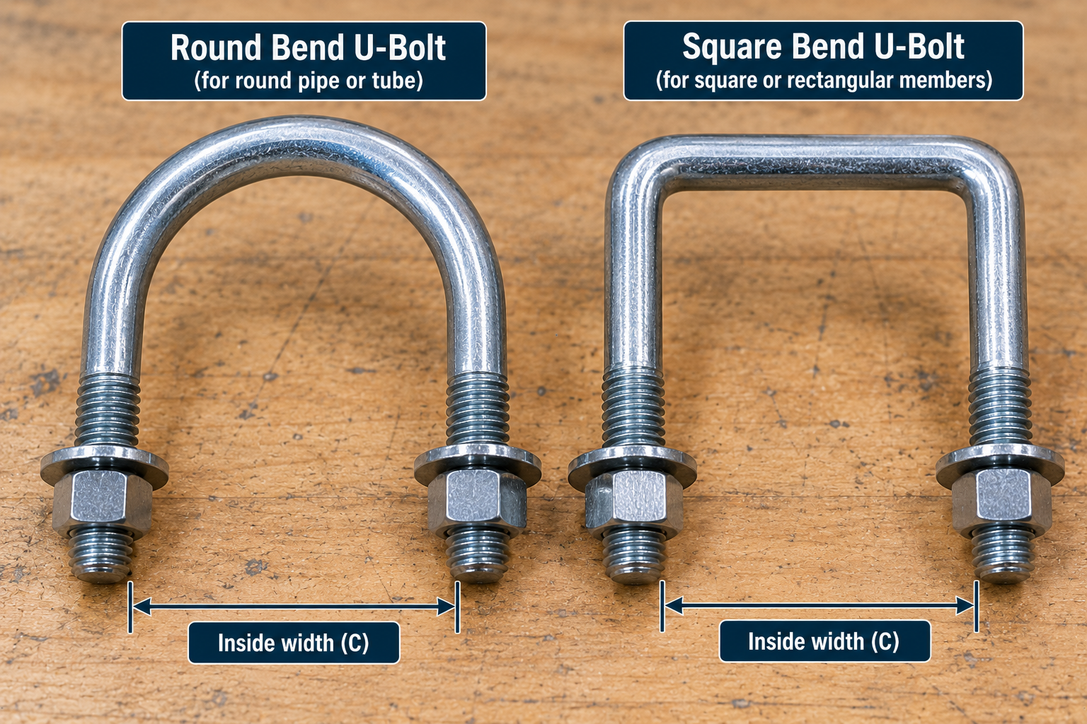
Round-bend U-bolts wrap pipe, tube and other round members. ASME B18.31.5 includes dimensional requirements for round-bend U-bolts. The bend radius and the inside width must fit the actual supported object.
Square U-Bolt Sizes
Square U-bolts go around square tubing, rectangular members, frames and equipment parts. Selection must consider both the member’s width and its depth, and the corner radius matters.
| Feature | Round Bend | Square Bend |
|---|---|---|
| Bend shape | Semicircular | Flat top with corner bends |
| Common fit | Pipe, tube and round objects | Square and rectangular members |
| Critical sizing | Inside width and bend fit | Inside width and inside length |
| Selection basis | Actual OD and the product drawing | Member dimensions and the product drawing |
Metric U-Bolt Sizes
Metric U-bolts are commonly written as the thread size, inside width and inside length, such as M10 × inside width × inside length, depending on the supplier. Convert inches to millimeters with:
3/8 in. Rod in Millimeters
Practical interpretation: 3/8 in. converts to 9.525 mm, but that does not make a 3/8 in. UNC U-bolt interchangeable with an M10 U-bolt. Thread systems differ. See the Metric Thread Chart.
| Rod Diameter (in.) | Millimeters |
|---|---|
| 1/4 | 6.350 |
| 5/16 | 7.938 |
| 3/8 | 9.525 |
| 7/16 | 11.112 |
| 1/2 | 12.700 |
| 5/8 | 15.875 |
| 3/4 | 19.050 |
| 7/8 | 22.225 |
| 1 | 25.400 |
Equipment for Your Project
Affiliate disclosure: As an Amazon Associate, ConcreteCalculate earns from qualifying purchases. We may also earn a commission from other affiliate links at no additional cost to you.
U-Bolt Materials and Grades
U-bolts are made from low-carbon steel, higher-strength or alloy steel, stainless steel and application-specific materials. Fastenal’s zinc-plated U-bolt standard specifies ASTM A307 Grade A material and mechanical requirements. ASTM A307 Grade A has a 60 ksi minimum tensile strength and is intended for general applications. Do not describe every carbon-steel U-bolt as ASTM A307, and do not treat 60 ksi as the strength of every U-bolt.
| Requirement | Specification |
|---|---|
| Material | Grade A per ASTM A307 |
| Mechanical | Grade A per ASTM A307 |
| Threads | ASME B1.1, UNC and UNF, Class 1A |
| Finish | Fe/Zn 3AN per ASTM F1941/F1941M |
Zinc-Plated, Galvanized and Stainless U-Bolts
Choose the finish for the exposure, moisture, corrosive environment, temperature and material compatibility. ASC offers plain, zinc-plated, hot-dip galvanized and stainless steel options depending on the product configuration.
| Finish | Typical Use | Note |
|---|---|---|
| Plain steel | Indoor, dry service | Little corrosion protection |
| Zinc electroplated | Indoor and mildly corrosive service | Thin coating |
| Hot-dip galvanized | Outdoor and wetter service | ASC leaves coating acceptability above 450°F to the end user |
| Stainless steel | Corrosive environments | Check material compatibility and load data |
U-Bolt Strength and Load Capacity
Size does not equal load rating. Capacity depends on the rod diameter, the material specification, thread condition, bend geometry, installation, direction of loading, support configuration, temperature and the manufacturer’s design. ASC publishes normal and side load capacities for its engineered Fig. 137 pipe-support U-bolt instead of relying on rod diameter alone, and it provides a straight-line interaction check, Pn/Pna + Ps/Psa ≤ 1, for combined loads. Its side-load values assume the nuts are snug tight.
U-Bolt Tensile Stress Area
For engineering explanation only, stress is force divided by area:
where σ is stress, P is the applied axial force and A is the resisting area. Threaded fasteners usually use the thread tensile stress area, not the full rod area.
| Nominal Diameter (in.) | UNC Thread | Tensile Stress Area (in²) |
|---|---|---|
| 1/4 | 1/4-20 | 0.0318 |
| 5/16 | 5/16-18 | 0.0524 |
| 3/8 | 3/8-16 | 0.0775 |
| 7/16 | 7/16-14 | 0.1063 |
| 1/2 | 1/2-13 | 0.1419 |
| 5/8 | 5/8-11 | 0.2260 |
| 3/4 | 3/4-10 | 0.3345 |
| 7/8 | 7/8-9 | 0.4617 |
| 1 | 1-8 | 0.6057 |
This is not a U-bolt load calculator. A U-bolt has two legs, a bend and a clamped object, and its capacity comes from the manufacturer’s design data.
Pipe Support U-Bolts
Engineered pipe-support U-bolts are a different product class from general-purpose clamps. ASC’s Fig. 137 Standard U-Bolt is recommended for support or guiding of heavy loads and is supplied with a carbon steel U-bolt and four finished hex nuts. ASC’s product page lists 1/2 through 36 in. pipe sizes and its submittal lists 3/4 through 36 in. The product complies with MSS SP-58 (Type 24), MSS SP-69 and related federal specifications. It is ordered by pipe size and rod size, for example 6 in. × 5/8 in.
Load-rated support selection needs the applicable support data. For support spacing see the Pipe Support Spacing Chart.
U-Bolts for Square and Rectangular Tubing
For square and rectangular tubing, take the inside width from the member width, and the inside length from the member depth plus any mounting plate and hardware. Choose the rod diameter from the design requirements. Do not apply nominal pipe-size charts to non-round members.
U-Bolt Plates, Saddles, Nuts and Washers
Accessories change the length you need. Saddle plates, flat mounting plates, washers, hex nuts, double nuts where specified, and liners or coatings all add to the stack. ASC’s Fig. 137 standard configuration includes four finished hex nuts. Match nuts and washers using the Nut Size Chart and the Washer Size Chart.
How to Select the Correct U-Bolt Size
- Identify the object being clamped.
- Determine its actual OD or member width.
- Select the bend style.
- Determine the required inside width.
- Determine the required inside length.
- Select the rod diameter from design and load requirements.
- Select the thread series.
- Verify the thread length.
- Select the material and finish.
- Check the manufacturer’s tolerances and load data.
Fastenal Pipe U-Bolt Lookup
The lookup covers only Fastenal product standard UBOLT.Z Rev. 07. Use it as an example, not as a universal sizing tool.
Worked U-Bolt Selection Examples
Pipe U-Bolt Example
U-Bolt for Nominal 2-in. Pipe
Practical interpretation: This is a product example, not a sizing formula. Confirm length, thread, material and load needs for your assembly.
Existing U-Bolt Replacement
Replacing an Unknown U-Bolt
Practical interpretation: Confirm the supplier’s definition of L and the material and finish.
U-Bolt Installation and Tightening
Tighten the nuts evenly, keep the U-bolt aligned and avoid spreading the legs. Set the saddle or plate in the correct position, protect the pipe or its coating where needed, and follow the manufacturer’s torque instructions. There is no universal U-bolt torque chart, because torque depends on material, diameter, thread condition, finish, lubrication, nuts and application. For general fastener torque references see the Bolt Torque Chart, which is not a U-bolt rating.
Common U-Bolt Sizing Mistakes
Treating nominal pipe size as actual OD
Nominal size is a designation.
Measuring outside width instead of inside width
Use the inner leg faces.
Ignoring rod diameter
It sets the thread and strength basis.
Ignoring thread pitch
Coarse and fine threads differ.
Confusing inside length with overall length
Check the supplier’s definition.
Ignoring thread length
Usable thread must remain after assembly.
Assuming every manufacturer’s dimensions are identical
Product drawings govern.
Selecting rod diameter from fit alone
Load requirements matter.
Treating ASTM A307 as a dimensional standard
It covers material and mechanical requirements.
Assuming galvanized and stainless U-bolts rate the same
Check the data for each.
Using a generic U-bolt as an engineered pipe support
Support products have their own data.
Assuming 3/8 in. and M10 are interchangeable
Thread systems differ.
Tightening without considering pipe or member damage
Protect coatings and walls.
Limitations
What This Chart Does Not Establish
This page is a general U-bolt dimensional reference. The main chart uses one manufacturer’s product dimensions, and ASME B18.31.5 provides the standardized dimensional context. It does not establish load capacity, structural support design or certification of any U-bolt. Use the exact manufacturer drawing and load data. For related references see the Construction Charts hub.
U-Bolt Size FAQs
How are U-bolts sized?
What does U-bolt size mean?
How do I measure a U-bolt?
Is U-bolt width measured inside or outside?
What size U-bolt fits 2-inch pipe?
Is nominal pipe size the same as pipe OD?
What does 3/8-inch U-bolt mean?
What thread does a 3/8-inch U-bolt use?
What is U-bolt inside length?
What is the difference between round and square U-bolts?
Are 3/8-inch and M10 U-bolts interchangeable?
How do I choose U-bolt material?
How much weight can a U-bolt hold?
Are U-bolt dimensions standardized?
Save the U-Bolt Size Chart as a PDF
Use your browser print function to save this reference for the shop, estimating folders and pipe-support planning.