Jack Stud Chart – Number Required, Sizes and Framing Guide
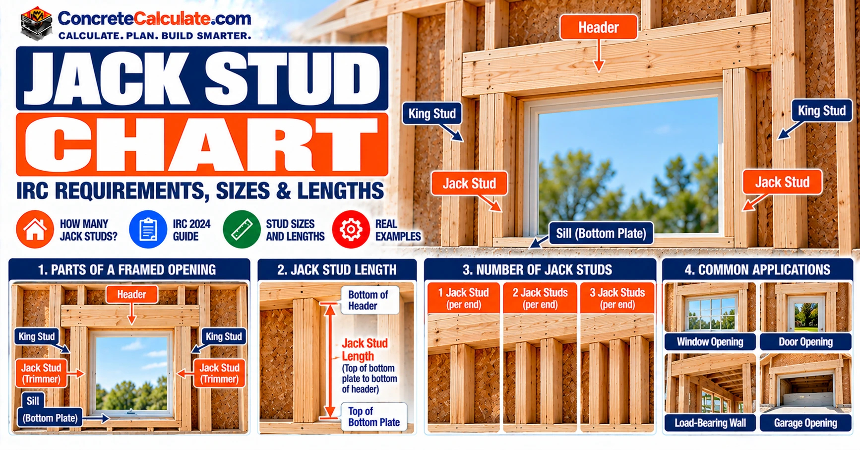
Jack Stud ChartNumber Required, Sizes and Framing Guide
A code-based reference for carpenters, framers, inspectors and homeowners: how many jack studs support each header end, how jack studs differ from king and cripple studs, and how to find bearing length and cut length.
Jump to the Chart Reviewed by Muhammad Ramzan Babar, PhD Researcher (Plasma Physics) & Calculator Developer, View Profile
Key Facts
- The number of jack studs comes from the IRC header tables, not from opening width alone. The 2024 tables list one, two or three jack studs per header end.
- Jack studs support the header. King studs run full height. Their counts are separate checks (Tables R602.7(1) and (2) vs. Table R602.7.5).
- Jack stud length = header underside elevation minus bottom plate top elevation.
Jack Stud Chart: Quick Reference
Required jack studs per header end from the 2024 IRC, with every condition stated.
The number of jack studs under a header comes from the IRC header tables, not from the opening width alone. This chart shows one clearly defined slice of the 2024 IRC so every number has stated conditions. For choosing the header itself, see the Header Size Chart.
How to Read This Chart
(2) 2×8 means a two-ply header made from nominal 2×8 lumber. Choose your building width, find the header size, and read the maximum tabulated span and the jacks per end (NJ). Jacks per end is the number at each end of the header. The span is the maximum for that header and width. A shorter opening does not automatically reduce the jack count; use a permitted header-and-support combination from the table.
| Header size | 12-ft building: max. span | Jacks per end | 24-ft building: max. span | Jacks per end | 36-ft building: max. span | Jacks per end |
|---|---|---|---|---|---|---|
| (2) 2×4 | 4 ft 0 in. | 1 | 3 ft 1 in. | 1 | 2 ft 7 in. | 1 |
| (2) 2×6 | 6 ft 0 in. | 1 | 4 ft 7 in. | 1 | 3 ft 10 in. | 1 |
| (2) 2×8 | 7 ft 7 in. | 1 | 5 ft 9 in. | 1 | 4 ft 10 in. | 2 |
| (2) 2×10 | 9 ft 0 in. | 1 | 6 ft 10 in. | 2 | 5 ft 9 in. | 2 |
| (2) 2×12 | 10 ft 7 in. | 2 | 8 ft 1 in. | 2 | 6 ft 10 in. | 2 |
- Conditions: exterior bearing wall, roof and ceiling only, 30 psf ground snow load, No. 2 grade lumber of the listed species groups, header top laterally braced as the table assumes, building widths of 12, 24 and 36 ft.
- This table does not give the number of full-height king studs. Those are checked separately in IRC Table R602.7.5, shown below.
- Snow loads of 50 and 70 psf and floor-supporting conditions are not in this simplified chart.
- The adopted IRC edition, table footnotes, approved plans and local amendments govern.
Source: 2024 International Residential Code, Table R602.7(1), exterior bearing walls, roof and ceiling only, 30 psf ground snow load, No. 2 grade Douglas fir-larch, hem-fir, southern pine and spruce-pine-fir. Building width is measured perpendicular to the ridge, and widths between the listed columns may be interpolated.
What Is a Jack Stud?
Definition and Purpose
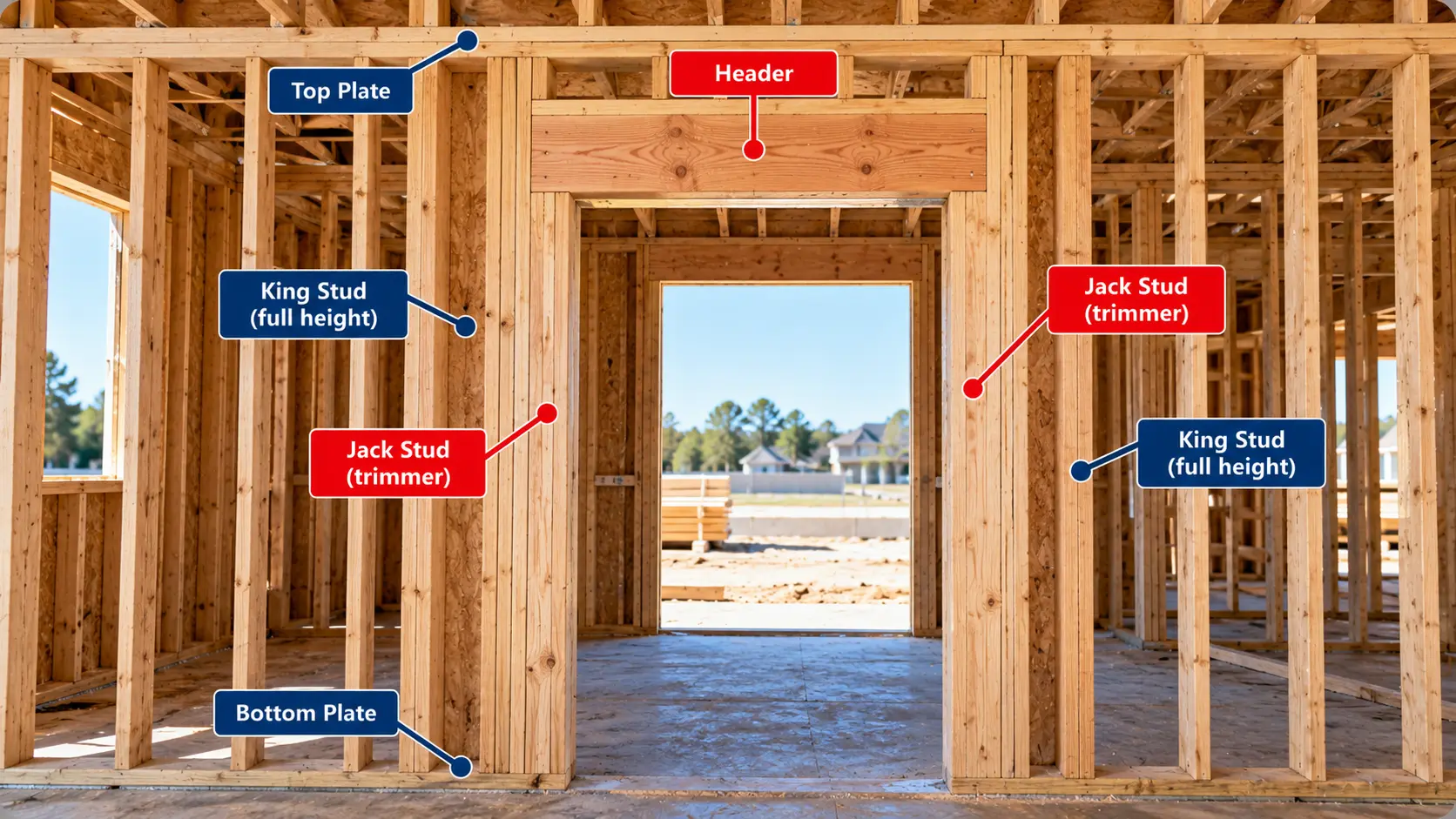
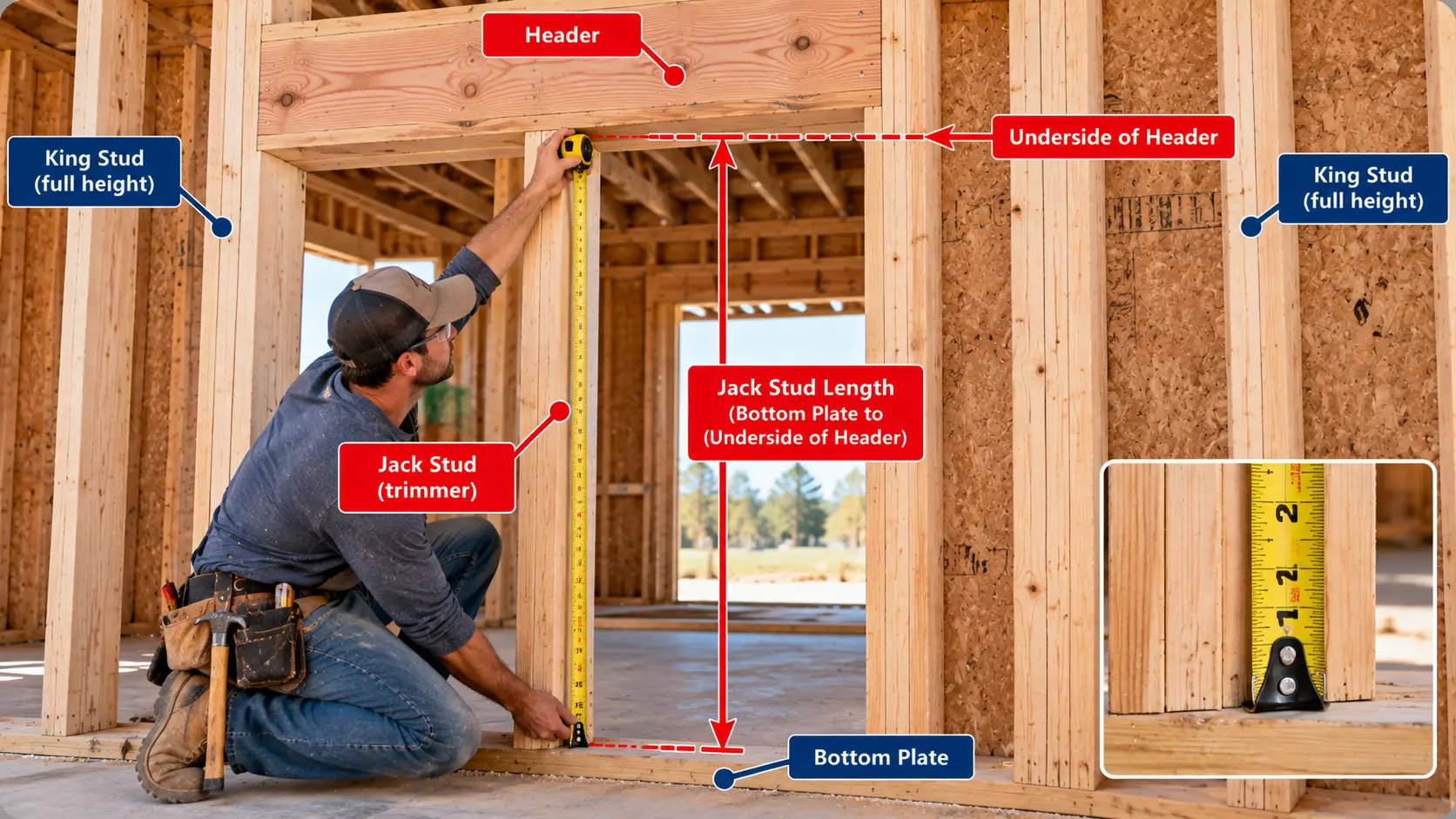
A jack stud is a shorter vertical framing member placed directly beneath the end of a header at the side of a door or window opening. It carries the header’s end reaction down into the bottom plate and the structure below. Jack studs also help hold the rough-opening geometry.
A jack stud normally runs from the top of the bottom plate to the underside of the header. It works with the full-height stud beside it to form the opening assembly.
Jack Stud vs. Trimmer Stud
In U.S. wood framing, jack stud and trimmer stud usually mean the same member. The IRC uses the term jack stud and counts them with the symbol NJ.
Jack Studs in Door and Window Framing
Door Openings
A door opening has a header, jack and king studs on each side, and cripple studs above the header. It has no sill, so the jack studs usually run from the bottom plate to the header. See the Door Rough Opening Chart for opening dimensions.
Window Openings
A window opening adds a rough sill and short cripple studs below it. The sill closes the bottom of the opening, but the header’s load goes down the jack studs, not through the sill. See the Window Rough Opening Chart for rough-opening sizes.
Header Support
In both cases the jack studs provide the bearing under the header ends. The number of jack studs and the number of full-height studs are separate code checks.
Jack Stud Building Code Requirements
The 2024 International Residential Code sets header support in Section R602.7. The tables list NJ, the number of jack studs needed to support each end of the header, for each header size, span, building width and load condition.
| IRC reference | What it covers |
|---|---|
| R602.7 | Headers: where headers are required and where to find spans |
| Table R602.7(1) | Header spans and jack studs (NJ) for exterior bearing walls |
| Table R602.7(2) | Header spans and jack studs (NJ) for interior bearing walls |
| Table R602.7(3) | Header spans for qualifying open porches |
| R602.7.4 | Headers in interior and exterior nonbearing walls |
| R602.7.5 and Table R602.7.5 | Header support and the minimum number of full-height studs at each end |
| Table R602.3(1) | Fastening schedule for framing connections |
IRC R602.7
Headers over openings in bearing walls must be sized from the tables or designed. The maximum spans themselves are covered in the Header Span Chart.
Exterior and Interior Header Tables
Table R602.7(1) covers exterior bearing walls and varies by ground snow load and by what the wall supports. Table R602.7(2) covers interior bearing walls and varies by the number of floors supported.
Header Support Rules
Section R602.7.5 requires headers to be supported at each end by jack studs or approved framing anchors as the tables allow. The full-height stud next to each header end must be end-nailed to the header in accordance with Table R602.3(1), and the minimum count of full-height studs follows Table R602.7.5.
Edition and Local Adoption
The 2024 IRC is a reference edition. The locally adopted code, any amendments and the approved plans control the job.
How Many Jack Studs Are Required?
The IRC range runs from one to three jack studs per end, and which one applies depends on the header, the building width, the roof and snow load and what the wall supports. Look at these rows from the 2024 table.
| Header | Building width | Max. tabulated span | Jacks per end |
|---|---|---|---|
| (2) 2×6 | 12 ft | 6 ft 0 in. | 1 |
| (2) 2×6 | 24 ft | 4 ft 7 in. | 1 |
| (2) 2×8 | 36 ft | 4 ft 10 in. | 2 |
| (2) 2×10 | 24 ft | 6 ft 10 in. | 2 |
| (1) 2×12 | 36 ft | 4 ft 7 in. | 3 |
Single Jack Studs
One jack per end is common for smaller headers and narrower buildings. Where the table lists one, an approved framing anchor may replace it, as explained later.
Double Jack Studs
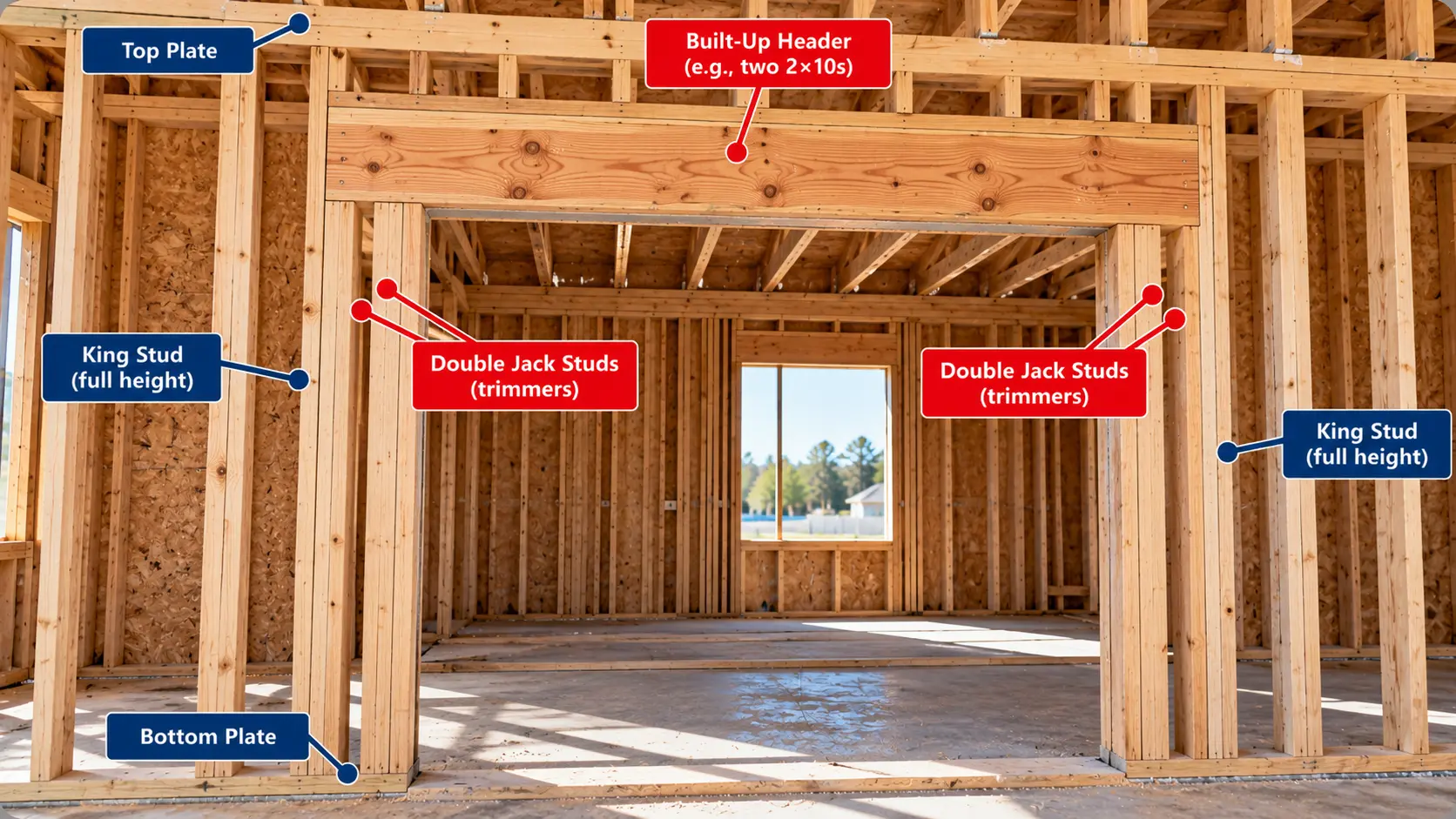
Two jacks per end appear as headers get larger or loads get heavier. Doubling the jacks doubles the bearing length under the header end.
Triple Jack Studs
Three jacks per end occur in heavier cases, such as a single-ply 2×12 header in a 36 ft wide building. Heavier snow columns can also reach three jacks for large headers.
| Header | Building width | Max. tabulated span | Jacks per end |
|---|---|---|---|
| (2) 2×8 | 24 ft | 5 ft 9 in. | 1 |
| (2) 2×10 | 24 ft | 6 ft 10 in. | 2 |
| (2) 2×10 | 12 ft | 9 ft 0 in. | 1 |
| (2) 2×10 | 36 ft | 5 ft 9 in. | 2 |
No Width-Only Rule
Never use a rule such as one jack stud for openings up to 4 ft and two for 4 to 8 ft. The IRC tables do not work that way.
Jack Stud Chart for Exterior Bearing Walls
The main chart at the top of the page is the exterior bearing-wall slice. Here is how its conditions change the answer.
Header Sizes
Bigger headers span farther, but they can also need more jack studs because they carry more load to each end.
Building Width
Width is measured perpendicular to the ridge. A wider building puts more roof load on the wall, so spans fall and jack counts rise, as the 12, 24 and 36 ft columns show.
Roof and Snow Loads
Heavier ground snow shortens spans and can add a jack. The table below uses a 24 ft building to show the effect.
| Header | 30 psf: span / jacks | 50 psf: span / jacks | 70 psf: span / jacks |
|---|---|---|---|
| (2) 2×6 | 4 ft 7 in. / 1 | 3 ft 11 in. / 1 | 3 ft 6 in. / 2 |
| (2) 2×8 | 5 ft 9 in. / 1 | 5 ft 0 in. / 2 | 4 ft 5 in. / 2 |
| (2) 2×10 | 6 ft 10 in. / 2 | 5 ft 11 in. / 2 | 5 ft 3 in. / 2 |
| (2) 2×12 | 8 ft 1 in. / 2 | 6 ft 11 in. / 2 | 6 ft 2 in. / 2 |
The full 2024 table also covers headers that support additional floors. Use the complete code table, not this slice, for those conditions.
Jack Stud Chart for Interior Bearing Walls
Interior bearing walls carry floor loads, not snow, so their table has no snow-load columns. The conditions are the number of floors supported and the building width.
One-Floor Loads
| Header size | 12-ft building: max. span | Jacks per end | 24-ft building: max. span | Jacks per end | 36-ft building: max. span | Jacks per end |
|---|---|---|---|---|---|---|
| (2) 2×4 | 4 ft 1 in. | 1 | 2 ft 10 in. | 1 | 2 ft 4 in. | 1 |
| (2) 2×6 | 6 ft 1 in. | 1 | 4 ft 4 in. | 1 | 3 ft 6 in. | 1 |
| (2) 2×8 | 7 ft 9 in. | 1 | 5 ft 5 in. | 1 | 4 ft 5 in. | 2 |
| (2) 2×10 | 9 ft 2 in. | 1 | 6 ft 6 in. | 2 | 5 ft 3 in. | 2 |
| (2) 2×12 | 10 ft 9 in. | 1 | 7 ft 7 in. | 2 | 6 ft 3 in. | 2 |
Two-Floor Loads
Two floors cut the spans sharply. A (2) 2×6 header spans 6 ft 1 in. in a 12 ft building under one floor but only 3 ft 11 in. under two. The one-floor chart must never be used for a wall supporting two floors.
| Header size | 12-ft building: max. span | Jacks per end | 24-ft building: max. span | Jacks per end | 36-ft building: max. span | Jacks per end |
|---|---|---|---|---|---|---|
| (2) 2×4 | 2 ft 7 in. | 1 | 1 ft 11 in. | 1 | 1 ft 7 in. | 1 |
| (2) 2×6 | 3 ft 11 in. | 1 | 2 ft 11 in. | 2 | 2 ft 5 in. | 2 |
| (2) 2×8 | 5 ft 0 in. | 1 | 3 ft 8 in. | 2 | 3 ft 1 in. | 2 |
Header Support
Header spans in both tables assume the header top is laterally braced by perpendicular framing. Where it is not (for example, cripple studs bearing on the header), the tabulated spans for 2×8, 2×10 and 2×12 headers are multiplied by 0.70, or the header must be designed. Where the table lists one jack, an approved framing anchor can replace it.
Jack Studs for Nonbearing Walls
Section R602.7.4 says load-bearing headers are not required in interior or exterior nonbearing walls.
Nonbearing Headers
A nonbearing wall carries only its own weight, so the bearing-wall header tables do not apply to it.
IRC Exceptions
For openings up to 8 ft wide, a single flat 2×4 may be used as a header in a nonbearing wall if the vertical distance to the parallel nailing surface above is not more than 24 inches. For such nonbearing headers, cripples or blocking are not required above the header.
Framing Requirements
Even where no structural header is needed, the opening still needs framing that suits the finishes and any bracing or connection requirements. Check the plans before assuming a partition is nonbearing.
Confirm the Wall Is Nonbearing
Do not treat a wall as nonbearing just because it is interior. Check the joist and rafter direction and the approved plans first.
Jack Stud vs. King Stud
Jack and king studs sit side by side, which is why they get confused. They have different jobs and different code counts.
| Framing member | Position | Main function | Typical length |
|---|---|---|---|
| Jack stud (trimmer) | Directly below the header end | Supports the header reaction | Bottom plate to header underside |
| King stud | Beside the jack and the opening | Full-height framing and the connection path to the plates | Bottom plate to top plate |
| Cripple stud above header | Header to top plate | Transfers load where applicable; provides framing and backing | Header top to top plate |
| Cripple stud below window | Bottom plate to rough sill | Supports the sill and completes the framing | Bottom plate to rough sill |
| Header | Across the opening | Carries loads to its supports | Sized for the opening and load |
Location
The jack is inside, directly under the header. The king is outside it and runs the full wall height.
Structural Function
The jack bears the header. The king ties the opening assembly to the top and bottom plates and takes the end nailing from the header.
Required Counts
The jack count comes from Tables R602.7(1) and R602.7(2). The full-height count comes from Table R602.7.5. One does not set the other. Wall layout is in the Stud Spacing Chart.
Jack Stud vs. Cripple Stud
A cripple stud is a short stud above a header or below a window sill.
Above-Header Cripples
These run from the top of the header to the top plate. In a bearing wall they can pass vertical load to the header, so they should not be called nonstructural.
Below-Sill Cripples
These run from the bottom plate to the rough sill and support the sill and window framing.
Framing Differences
Cripples bearing on the header mean its top is not laterally braced by perpendicular framing, so the 0.70 span factor in the table footnotes applies to 2×8, 2×10 and 2×12 headers, unless the header is designed. For example, a (2) 2×10 header tabulated at 6 ft 10 in. (82 in.) would be limited to about 57 in. (82 × 0.70 = 57.4 in.). Confirm the jack count with the code footnotes or the designer.
King Stud Requirements Under IRC R602.7.5
Full-height studs, often called king studs, run from the bottom plate to the top plate beside the opening. Table R602.7.5 sets the minimum number at each end of an exterior header from the header span and the wind condition. These are full-height stud counts, not jack stud counts.
Full-Height Stud Counts
| Maximum header span | Wind category A: full-height studs per end | Wind category B: full-height studs per end |
|---|---|---|
| 4 ft | 1 | 1 |
| 6 ft | 2 | 1 |
| 8 ft | 2 | 1 |
| 10 ft | 3 | 2 |
| 12 ft | 3 | 2 |
| 14 ft | 3 | 2 |
| 16 ft | 4 | 2 |
| 18 ft | 4 | 2 |
- For spans between those listed, use the count for the next larger listed span.
- The tabulated counts apply where jack studs support the header at each end in accordance with Table R602.7(1).
- Where an approved framing anchor replaces a jack stud, the full-height count must follow the wind category A requirements (below 140 mph, Exposure B).
Wind Conditions
The lower category B column applies only up to 115 mph in Exposure B. Heavier wind raises the count. For example, a header spanning 6 ft needs two full-height studs per end in category A but one in category B.
Header Span
The count can exceed the jack count. A 12 ft header needs three full-height studs per end in category A even if the jack table calls for two jacks.
Source: 2024 IRC Table R602.7.5, Minimum Number of Full-Height Studs at Each End of Headers in Exterior Walls.
Jack Stud Sizes and Lumber Dimensions
2×4 and 2×6 Studs
Jack studs normally match the wall studs, so a 2×4 wall uses 2×4 jacks and a 2×6 wall uses 2×6 jacks. The jack should be as deep as the wall so the header and finishes stay flush.
Actual Dimensions
Dimension lumber is smaller than its name. The table below lists the standard dressed sizes. The 1-1/2 in. thickness is the number that sets bearing length, and the depth numbers are what you subtract when finding header depth. See the Lumber Size Chart for more sizes.
| Nominal lumber | Actual thickness | Actual width |
|---|---|---|
| 2×4 | 1-1/2 in. | 3-1/2 in. |
| 2×6 | 1-1/2 in. | 5-1/2 in. |
| 2×8 | 1-1/2 in. | 7-1/4 in. |
| 2×10 | 1-1/2 in. | 9-1/4 in. |
| 2×12 | 1-1/2 in. | 11-1/4 in. |
Lumber Selection
Studs must meet the minimum grade in IRC Section R602.2, and the header tables assume No. 2 grade header lumber. Do not swap in a larger or different member without checking compatibility and loads against the plans.
Jack Stud Length Chart
Header Underside Elevation
Jack length depends on where the underside of the header sits, not on the wall height alone.
Bottom Plate Elevation
Measure from the top of the bottom plate, which is 1-1/2 in. above the floor reference in this example.
Cut-Length Examples
| Header member depth | Actual header depth Dh | Jack cut length Lj = 90 – Dh |
|---|---|---|
| 2×6 | 5-1/2 in. | 84-1/2 in. |
| 2×8 | 7-1/4 in. | 82-3/4 in. |
| 2×10 | 9-1/4 in. | 80-3/4 in. |
| 2×12 | 11-1/4 in. | 78-3/4 in. |
If the header is installed lower to leave room for cripple studs above it, the cut length must be recalculated from the actual header underside elevation. The ply count does not change the depth, so a (2) 2×10 header still has a 9-1/4 in. depth.
How to Calculate Jack Stud Length
Formula
Use the elevation-based formula when you know where the header underside sits. Use the header-depth formula when the header sits directly under the top plates.
Measurements
Take the measurements from the actual installed header and plates, not from the plan. Rough-opening dimensions must be verified in the field.
Worked Examples
Elevation-Based Jack Stud Length
Variables: Lj = jack stud cut length; Eh = elevation of the header underside; Eb = elevation of the top of the bottom plate (same datum for both)
Practical interpretation: This is the geometric length for the stated elevations. Field dimensions and tolerances must still be checked.
Header-Depth Jack Stud Length
Variables: Hu = clear distance from the top of the bottom plate to the underside of the top plates; Dh = actual header depth
Practical interpretation: Use this form only when the header sits directly under the top plates. If cripples or other framing sit between them, use the elevation formula.
Jack Stud Bearing Width
Single and Double Jacks
Each standard 2× jack adds 1-1/2 in. of bearing length along the header. Two jacks give 3 in.
| Jack studs at one header end | Combined nominal bearing length along the header |
|---|---|
| 1 | 1-1/2 in. |
| 2 | 3 in. |
| 3 | 4-1/2 in. |
| 4 | 6 in. |
Triple Jacks
Combined Bearing Length
Variables: b = combined bearing length along the header; nj = jack studs at one end; t = actual thickness of one jack stud
Practical interpretation: This assumes alignment and full bearing. It does not establish structural adequacy.
Bearing Limitations
Geometric bearing length is not the same as bearing capacity. Allowable compression perpendicular to the grain, the header reaction and the load path below all decide whether the bearing is adequate. The code tables already account for those checks, which is why the count comes from the table.
Jack Stud Load Path and Structural Support
Header End Reactions
A header acts like a short beam. Its load splits between its two supports, so each end reaction is half the total for a uniform load.
Approximate Header End Reaction (educational)
Variables: w = uniform load per foot of header; L = header span; R = reaction at each end
Practical interpretation: This is a statics illustration. Actual loads come from structural design, and the jack stud count cannot be found by dividing the reaction by a presumed universal stud capacity.
Vertical Load Transfer
The load path runs from the roof or floor above, through the top plates and any cripple studs, into the header, then through the jack studs to the bottom plate and the structure below. The first drawing on this page shows that path.
Continuous Support
The Load Path Must Continue Below
Jack studs cannot make up for a missing or misaligned support below the bottom plate. Floor framing, blocking, beams or the foundation must carry the load down. For beam loading context, see the Wood Beam Span Chart.
Jack Studs for Door Openings
Interior Doors
Interior doors in bearing walls follow the interior header table. Interior doors in nonbearing walls may use the nonbearing header provision. Door framing dimensions are in the Door Rough Opening Chart.
Exterior Doors
Exterior doors are usually in bearing walls and use the exterior table. Entry doors with sidelights can create wide openings that need a header selected for the whole width.
Wide Openings
Wider openings carry larger reactions and more often need two or three jacks and extra full-height studs.
Garage door openings are wide and are frequently outside what dimension-lumber header tables cover, so they are commonly designed by an engineer or use engineered headers and special high-wind framing details.
Jack Studs for Window Openings
Header
A window header is sized like a door header from the same tables. The window’s own rough-opening size is in the Window Rough Opening Chart.
Rough Sill
The rough sill is a flat framing member at the bottom of the opening. It does not carry the header load.
King and Jack Placement
Place the jack studs inside the king studs at each side so the header ends sit on the jacks. The jacks run from the bottom plate to the header underside, and the sill fits between them.
Cripple Stud Arrangement
Cripples go above the header to the top plate and below the sill to the bottom plate, usually at the wall’s stud spacing.
Jack Studs for Large Headers and Wide Openings
Multiple Jacks
Large reactions can call for two or three jacks per end, and the full-height stud count grows with span as Table R602.7.5 shows. The single-ply row below reaches three jacks in a 36 ft building.
| Header size | 12-ft building: max. span | Jacks per end | 24-ft building: max. span | Jacks per end | 36-ft building: max. span | Jacks per end |
|---|---|---|---|---|---|---|
| (1) 2×12 | 7 ft 1 in. | 2 | 5 ft 5 in. | 2 | 4 ft 7 in. | 3 |
LVL Headers
The IRC tables above are for dimension lumber. Engineered headers such as LVL have their own bearing length and support requirements set by the manufacturer. Do not apply the sawn-lumber chart to an LVL header. For span selection, see the LVL Span Chart.
Engineered Details
Wide openings and concentrated loads call for an engineered detail, including the support beneath the jack studs.
Header Size vs. Jack Stud Count
Header selection answers span and loading. Jack stud selection answers end support. They are separate checks that interact through the table.
Header Span
A (2) 2×8 spans 5 ft 9 in. with one jack per end in a 24 ft building, and a (2) 2×10 spans 6 ft 10 in. but needs two.
| Header | Building width | Max. span | Jacks per end |
|---|---|---|---|
| (2) 2×8 | 24 ft | 5 ft 9 in. | 1 |
| (2) 2×10 | 24 ft | 6 ft 10 in. | 2 |
End Bearing
A bigger header often moves more load to each end, which is why the count can rise.
Separate Design Checks
A header may be large enough to span an opening and still need more jacks. Adding jacks does not make an undersized header adequate. Full header sizing stays on the Header Size Chart.
Jack Stud Alternatives and Header Hangers
Approved Framing Anchors
A footnote to Tables R602.7(1) and R602.7(2) says that where the number of required jack studs equals one, the header is permitted to be supported by an approved framing anchor attached to the full-height wall stud and to the header. APA advanced-framing guidance also shows header hangers and single-ply headers as framing options.
IRC Exceptions
This exception applies only to the single-jack case. It does not remove jack studs from openings that need two or three, and it changes the full-height stud count: Table R602.7.5 requires the wind category A counts where an anchor replaces a jack stud.
Installation Requirements
Use the Exact Approved Connector
The connector must have an approved installation, adequate capacity for the actual reaction, and the manufacturer’s specified fasteners. Header hangers from different makers are not interchangeable.
A single flat member used as a header (Section R602.7.1) has its own framing and nailing rules and is a different detail.
Jack Stud Fastening and Connections
This page does not set one nail schedule for every jack stud assembly. The IRC lists specific rows, and the plans or connector maker may require more.
| Connection | Listed fastening alternatives | Method |
|---|---|---|
| Built-up header (2 in. to 2 in. with 1/2 in. spacer) | 16d common (3-1/2 × 0.162 in.) at 16 in. o.c. each edge; or 16d box (3-1/2 × 0.135 in.) at 12 in. o.c. each edge | Face nail |
| Continuous header to stud | 5-8d box (2-1/2 × 0.113 in.); or 4-8d common (2-1/2 × 0.131 in.); or 4-10d box (3 × 0.128 in.) | Toe nail |
| Adjacent full-height stud to end of header | 4-16d box (3-1/2 × 0.135 in.); or 3-16d common (3-1/2 × 0.162 in.); or 4-10d box (3 × 0.128 in.); or 4-3 × 0.131 in. nails | End nail |
| Top or bottom plate to stud | 3-16d box; or 2-16d common (3-1/2 × 0.162 in.); or 3-10d box; or 3-3 × 0.131 in. nails | End nail |
| Stud to stud, not at braced wall panels | 16d common (3-1/2 × 0.162 in.) at 24 in. o.c.; or 10d box (3 × 0.128 in.) or 3 × 0.131 in. nails at 16 in. o.c. | Face nail |
Jack-to-King Connections
The fastening schedule has no separate jack-to-king row, so ask the building official or designer how the jack and king are to be connected unless the plans show it. The stud-to-stud row is the closest listed entry.
Header Fastening
The full-height stud next to the header end is end-nailed to the header, and a continuous header is toe-nailed to the stud, as the table shows. Nail dimensions are in the Framing Nail Size Chart and the general Nail Size Chart.
Connector Requirements
Where a framing anchor is used, use the manufacturer’s connector nails and follow its installation instructions exactly.
How to Frame a Door or Window with Jack Studs
This sequence is a layout guide, not structural design. The plans and code tables decide sizes and counts.
Layout
- Confirm the plans, the wall type (bearing or nonbearing) and the header size.
- Lay out the rough opening and mark king, jack and cripple locations.
- Install the full-height king studs.
Cutting and Installation
- Measure the header underside elevation and cut the jack studs to length.
- Install the jack studs tight against the king studs and on the bottom plate.
- Set the header on the jack studs, tight to the top plates or with cripples above.
- Fasten the header, jacks and kings as the code schedule or plans require.
Inspection
- Check bearing, plumb, rough-opening size and the support below the bottom plate.
How to Estimate Jack Stud Quantities
Per-Opening Count
Find the required count from the applicable table or plan first. Then multiply by two ends.
| Opening configuration | Jacks at left end | Jacks at right end | Total jack studs |
|---|---|---|---|
| Single jacks | 1 | 1 | 2 |
| Double jacks | 2 | 2 | 4 |
| Triple jacks | 3 | 3 | 6 |
| Four per end | 4 | 4 | 8 |
Total Jack Studs for One Opening
Variables: Nj = total jack studs; NL, NR = jack studs at the left and right header ends
Practical interpretation: This does not include full-height king studs or cripple studs.
Multiple-Opening Count
Jack Studs for Several Openings
Variables: n = number of openings; N per end = required jacks per end (symmetrical supports)
Practical interpretation: Add a separate allowance for waste or damaged lumber only when preparing a purchasing estimate.
Material Takeoff
Count king studs and cripples separately. A takeoff for one opening with two jacks and one king per side has four jacks and two kings. Waste allowances belong to the purchasing estimate, not to the code count.
Common Jack Stud Framing Mistakes
Incorrect Counts
Using one jack stud for every opening
Some table cells need two or three.
Confusing jack studs with king studs
They have separate jobs and separate code counts.
Ignoring full-height stud requirements
Check Table R602.7.5 as well.
Selecting jacks using only opening width
Header, width and load decide the count.
Using a header chart for the wrong load condition
Floors above and snow change the table.
Ignoring building width and snow load
Both change the span and the count.
Using a nonbearing-wall rule in a bearing wall
Nonbearing allowances do not apply to bearing walls.
Cut-Length Errors
Cutting jack studs too short
A short jack leaves the header unsupported.
Leaving gaps beneath the header
The header must bear fully on the jacks.
Installing jack studs without proper bearing
Cut square and seat tight on the plate.
Bearing and Load-Path Errors
Ignoring support beneath the bottom plate
The load path must continue below.
Replacing jacks with unapproved connectors
Only approved anchors where the code allows.
Using incorrect fastening
Follow the code schedule or plans.
Assuming an LVL header follows the sawn-lumber chart
LVL support is product specific.
Ignoring wind and lateral-load requirements
Wind raises the full-height stud count.
Jack Stud Inspection Checklist
Header and Stud Verification
Check the header size, plies and span against the plans, then confirm the jack and king stud counts at each end.
| Inspection item | What to verify |
|---|---|
| Wall type | Bearing or nonbearing |
| Code edition | Locally adopted requirements |
| Header | Correct size, plies, grade and span |
| Jack studs | Required count at each end |
| King studs | Required full-height count |
| Lumber | Correct dimensions and grade |
| Cut length | Full bearing beneath the header |
| Load path | Continuous support below |
| Fastening | Code or approved plan |
| Connectors | Approved and correctly installed |
| Rough opening | Correct dimensions |
| Wind and bracing | Required framing details maintained |
Fastening
Check nail type, number and placement against the code schedule or the plans and connector instructions.
Structural Support
Confirm continuous support beneath the jacks, down to the foundation or a supporting beam.
Jack Stud Chart Limitations and Safety
Code and Design Limitations
This chart does not independently establish header structural capacity, jack stud compression capacity, bearing adequacy, foundation or floor support adequacy, full-height stud requirements in all wind conditions, engineered header compatibility, seismic or high-wind compliance, or structural adequacy after wall alterations.
Altering a Bearing Wall
For bearing-wall modifications, follow approved structural plans and obtain qualified professional review where required. The adopted code, the plans and the engineer control.
Structural Alterations
Removing or shortening jack studs in a remodel can overload the header and the framing below. Do not remove them without a design.
Primary References
Jack Stud FAQs
Sizes and Counts
What is a jack stud?
A jack stud, also called a trimmer, is a shorter vertical stud directly under the end of a header. It runs from the top of the bottom plate to the header underside and carries the header reaction down.
Is a jack stud the same as a trimmer stud?
In U.S. wood framing, yes. The two terms are used for the same member. The IRC uses jack stud.
How many jack studs are needed for a door?
There is no single number. In the 2024 IRC tables, the count per header end is one, two or three, depending on header size, building width, loads and whether the wall is bearing. A nonbearing wall may not need a bearing-wall header at all.
How many jack studs are needed for a window?
The same tables apply as for doors. The count depends on the header and loads, not on the window size alone.
Does every header need two jack studs?
No. Many 2024 table entries list one jack per end, such as a (2) 2×6 header in a 12 ft wide building. Others list two or three.
When are double jack studs required?
When the applicable table lists NJ = 2 for the header, such as a (2) 2×10 header at 24 ft building width in the 30 psf roof and ceiling slice.
When are triple jack studs required?
When the table lists NJ = 3. Examples include a single-ply 2×12 header in a 36 ft wide building, or a (2) 2×12 header at 70 psf ground snow and 36 ft width.
Can a header rest on one jack stud?
Yes where the applicable table lists one jack stud per end. The header is permitted to be supported by an approved framing anchor in that case as well.
Can a header hanger replace a jack stud?
Only where the table lists one jack stud and the connector is an approved framing anchor attached to the full-height stud and header. The full-height stud count then follows the higher wind category.
What is the difference between a king stud and a jack stud?
The jack stud sits under the header and supports it. The king stud runs from bottom plate to top plate beside the opening.
Are king studs and jack studs counted separately?
Yes. Jack stud counts come from Tables R602.7(1) and R602.7(2). Full-height stud counts come from Table R602.7.5.
How long should a jack stud be?
It runs from the top of the bottom plate to the underside of the header. In the example with a 90 in. clear height and a 2×10 header, the cut length is 80-3/4 in.
How do you calculate jack stud length?
Subtract the bottom plate top elevation from the header underside elevation, or subtract the actual header depth from the clear height when the header sits directly under the top plates.
Are jack studs needed in nonbearing walls?
Load-bearing headers are not required in nonbearing walls. A single flat 2×4 can serve for openings up to 8 ft where the nailing surface above is within 24 in.
Do LVL headers require more jack studs?
They can. Engineered headers use the manufacturer’s bearing and support requirements, so do not apply the sawn-lumber table.
What supports the load beneath a jack stud?
The bottom plate and the floor framing, blocking, beam or foundation below it. The load path must be continuous.
Can jack studs be removed during remodeling?
Not without a design. Removing them from a bearing opening can overload the header and the support below.
Which IRC table gives the number of jack studs?
Table R602.7(1) for exterior bearing walls and Table R602.7(2) for interior bearing walls. Table R602.7.5 gives full-height stud counts.
Download Jack Stud Chart PDF
Use your browser’s print function to save this page as a PDF for jobsite binders and plan sets. The printed version hides interactive elements and keeps the tables.