Header Size Chart: Wood Headers for Doors, Windows & Bearing Walls
Header Size Chart: Wood Headers for Doors, Windows & Bearing Walls
Common built-up header dimensions, plus the wall type, loads, building width, snow load, bracing and support factors that decide which header size works.
 Reviewed by Muhammad Ramzan Babar, PhD Researcher (Plasma Physics) & Calculator Developer. View Profile
Key Facts
- A header cannot be sized from the opening width alone. The IRC uses separate tables for exterior bearing walls, interior bearing walls and open porches, plus separate rules for nonbearing walls.
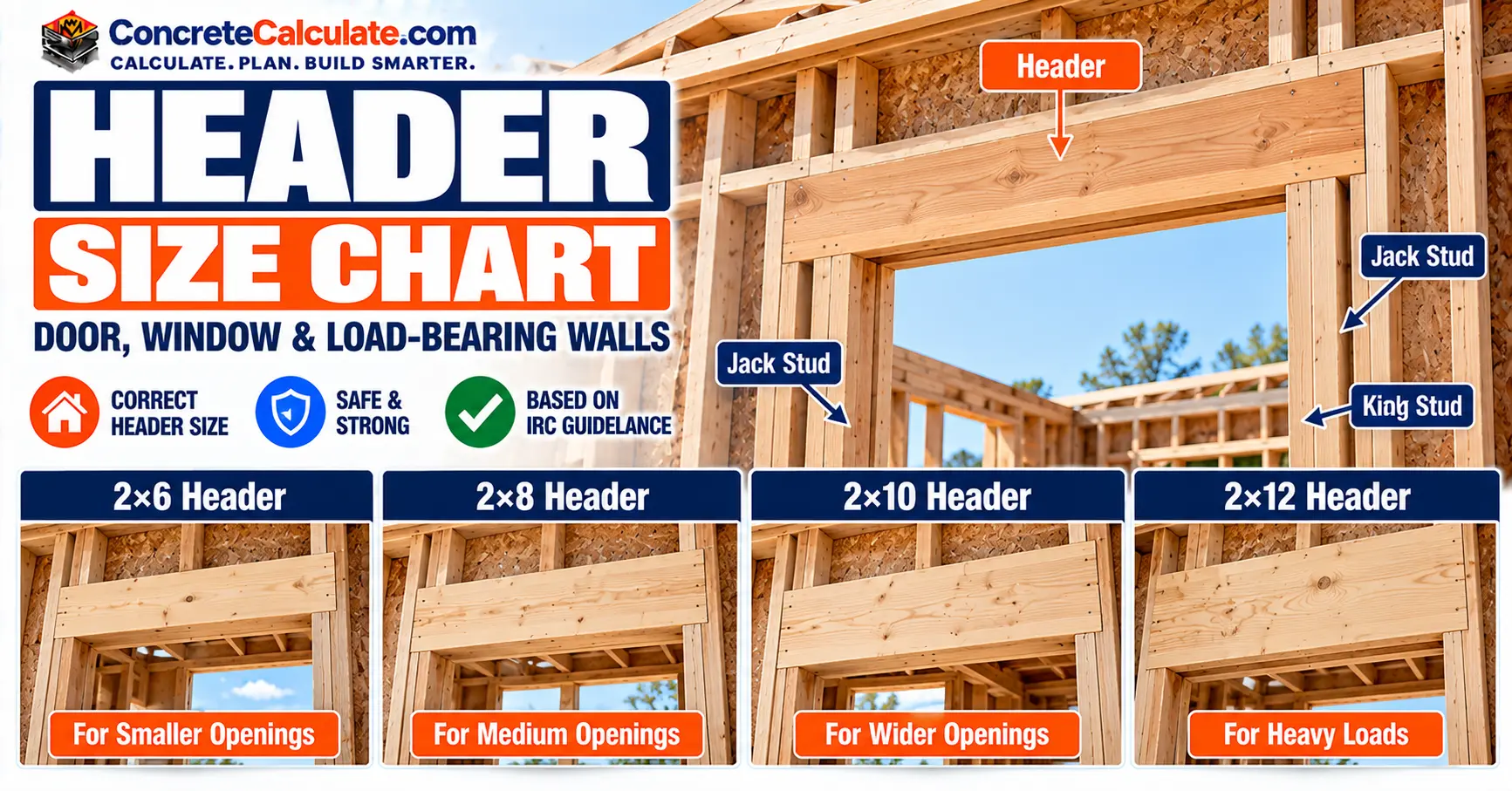
- Built-up headers are 1.5 in. wide per ply: (2) = 3 in., (3) = 4.5 in., (4) = 6 in., with actual depths of 5.5, 7.25, 9.25 or 11.25 in.
- Verified example (24-ft building, 30 psf snow, roof and ceiling only): (2) 2×6 to 4′-7″, (2) 2×8 to 5′-9″, (2) 2×10 to 6′-10″, with the jack studs shown in the chart below.
- For full span lookups, use the Header Span Chart. This page covers sizes and what determines them.
Header Size Chart: Double, Triple & Quadruple Lumber
Common built-up lumber header dimensions, with the warning that dimensions alone never set the span.
How to Read This Chart
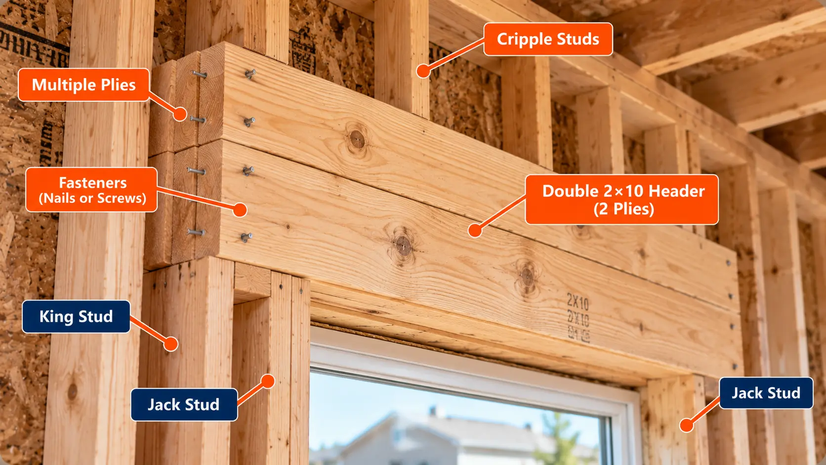
The configuration “(2) 2×8” means two 2×8 boards fastened face to face. Total width is 1.5 in. times the number of plies, and depth is the actual depth of one board. These are dimensions only. They do not tell you how far the header can span.
| Header configuration | Plies | Typical actual width (in.) | Actual depth (in.) | Approx. mm (converted) | Type |
|---|---|---|---|---|---|
| (2) 2×4 | 2 | 3 | 3.5 | 76 × 89 | Built-up dimensional lumber |
| (2) 2×6 | 2 | 3 | 5.5 | 76 × 140 | Built-up dimensional lumber |
| (2) 2×8 | 2 | 3 | 7.25 | 76 × 184 | Built-up dimensional lumber |
| (2) 2×10 | 2 | 3 | 9.25 | 76 × 235 | Built-up dimensional lumber |
| (2) 2×12 | 2 | 3 | 11.25 | 76 × 286 | Built-up dimensional lumber |
| (3) 2×8 | 3 | 4.5 | 7.25 | 114 × 184 | Built-up dimensional lumber |
| (3) 2×10 | 3 | 4.5 | 9.25 | 114 × 235 | Built-up dimensional lumber |
| (3) 2×12 | 3 | 4.5 | 11.25 | 114 × 286 | Built-up dimensional lumber |
| (4) 2×8 | 4 | 6 | 7.25 | 152 × 184 | Built-up dimensional lumber |
| (4) 2×10 | 4 | 6 | 9.25 | 152 × 235 | Built-up dimensional lumber |
| (4) 2×12 | 4 | 6 | 11.25 | 152 × 286 | Built-up dimensional lumber |
Dimensions Are Not Spans
These dimensions do not establish allowable header spans. Selection depends on the supported loads, building width, ground snow load, structural wall classification, lumber grade and species, bracing and required supports. A 3 in. wide double 2× header does not fill a typical 3-1/2 in. 2×4 wall cavity by itself. Spacers or other approved detailing may be used, but a spacer does not add structural capacity. For maximum spans under stated IRC conditions, use the Header Span Chart.
Common Double-Lumber Sizes
Two-ply headers are the most common built-up configuration: (2) 2×4, (2) 2×6, (2) 2×8, (2) 2×10 and (2) 2×12. Each ply is 1.5 in. thick, so the assembly is 3 in. wide.
Triple and Quadruple Headers
Three and four plies add width for more bending and bearing area. (3) assemblies are 4.5 in. wide and (4) assemblies are 6 in. wide. They are typically used in thicker walls or for heavier loads, and they must be fastened as the code and design require. The IRC tables list built-up headers from two to four plies, plus single-member options for specific table conditions.
Nominal vs. Actual Dimensions
A nominal 2×8 is 1.5 in. by 7.25 in. in actual dressed size, and a nominal 2×10 is 1.5 in. by 9.25 in. Always calculate with actual dimensions. See the Lumber Size Chart for every nominal-to-actual conversion.
What Is a Header in Wood Framing?
The member that carries load around an opening.
A structural header is a horizontal member above an opening that carries supported loads around the opening and into adjoining framing. It is used over door openings, window openings, garage doors, openings in interior bearing walls and porch openings. Not every opening needs a structural header; nonbearing walls follow a different rule covered later.
| Step | Member | What it does |
|---|---|---|
| 1 | Roof and floor load | Imposed load from the framing above |
| 2 | Header | Carries the load across the opening |
| 3 | Jack studs or designed supports | Receive the header ends and carry load down |
| 4 | Supporting framing and foundation | Resist the load into the ground |
What Determines Header Size?
Wall type, loads, building width, snow load, lumber, bracing and supports all take part.
The most important rule on this page: a header cannot be correctly selected from the opening width alone. The IRC provides separate header-sizing tables for different structural conditions, and the exterior-wall table adds the number of floors supported, the building width and the ground snow load.
| IRC reference | Application |
|---|---|
| Table R602.7(1) | Exterior bearing walls |
| Table R602.7(2) | Interior bearing walls |
| Table R602.7(3) | Open porches |
| Section R602.7.1 | Single-member headers |
| Section R602.7.2 | Rim board headers |
| Section R602.7.3 | Wood structural panel box headers |
| Section R602.7.4 | Nonbearing walls |
| Section R602.7.5 | Supports and full-height studs |
Variables That Decide Header Size
| Variable | Why it matters | Can it be ignored? |
|---|---|---|
| Wall classification | Bearing or nonbearing decides whether a table applies | No |
| Opening span | Structural span between supports | No |
| What the header supports | Roof and ceiling, one or two floors, porch roof or floor | No |
| Building width | Sets the tributary roof and floor load | No |
| Ground snow load | Changes span and jack studs in exterior walls | No |
| Species and grade | Set the design values behind the tables | No |
| Lateral bracing | May trigger the 0.70 span factor | No |
| Supports | Jack studs and full-height studs carry the reaction | No |
| Concentrated loads | Fall outside the prescriptive tables | No |
Header Size vs. Header Span
Design span, opening width and cut length are three different measurements.
Header size and header span are different things. The design span, Lh, is the structural span the header must clear between its supports. The cut length of the header, Lpiece, is the physical length of the member. The header needs bearing at its supports, so the cut length is longer than the clear opening.
A 6-ft opening cannot automatically be framed with a 6-ft-long header that has no bearing allowance. No single cut-length addition is correct for every framing design, because bearing and support details depend on the framing. For maximum spans by size under precisely stated conditions, use the Header Span Chart.
Where the Page Ownership Splits
This page answers what sizes exist and what determines the size. The Header Span Chart answers how far a particular header can span under stated IRC conditions.
Header Size vs. Rough Opening Width
Why the rough opening is not the same as the header span or the header length.
A nominal 36-in. door does not automatically need a 36-in. rough opening. The rough opening comes from the door or window manufacturer or the installation specifications. Keep these dimensions separate:
| Dimension | What it is | Where it comes from |
|---|---|---|
| Nominal unit size | The name of the door or window | Product catalog |
| Rough opening | Framed opening that receives the unit | Manufacturer instructions |
| Structural framed opening | Clear distance between supports | Framing design |
| Header span | Span used to read a header table | Structural span between supports |
| Header cut length | Full length of the header member | Header span plus bearing |
For manufacturer-dependent dimensions, use the Door Rough Opening Chart or the Window Rough Opening Chart. They own those dimensions, so this page does not repeat them.
Verified IRC Header Size Example
One IRC table column, four double headers, with spans and required jack studs side by side.
The table below comes from a single column of IRC Table R602.7(1): an exterior bearing wall supporting roof and ceiling only, 24-ft building width and 30 psf ground snow load, using minimum design properties for No. 2 Douglas Fir-Larch, Hem-Fir, Southern Pine or Spruce-Pine-Fir, with the top of the header laterally braced as the table footnote requires.
| Header configuration | Maximum tabulated span | Jack studs required at each end |
|---|---|---|
| (2) 2×4 | 3′-1″ | 1 |
| (2) 2×6 | 4′-7″ | 1 |
| (2) 2×8 | 5′-9″ | 1 |
| (2) 2×10 | 6′-10″ | 2 |
Critical Interpretation
Under these exact conditions a double 2×6 is tabulated to 4′-7″, a double 2×8 to 5′-9″ and a double 2×10 to 6′-10″. A deeper header can raise the tabulated span under fixed assumptions. That does not mean “a double 2×10 spans 6′-10″ in all houses.” The value applies only to the identified conditions, and the jack stud count comes from the same table cell.
How Building Width Affects Header Size
The same header, three building widths, three different spans.
Hold everything constant except building width, and the same double 2×8 header loses span as the building gets wider. A wider building usually means a larger supported roof and ceiling area, so more load reaches the header and the allowable span drops.
| Building width | Maximum tabulated header span | Jack studs per end |
|---|---|---|
| 12 ft | 7′-7″ | 1 |
| 24 ft | 5′-9″ | 1 |
| 36 ft | 4′-10″ | 2 |
Building Width Is Not Opening Width
Building width is measured perpendicular to the roof ridge, and the table allows interpolation between listed widths under its footnotes. It is not the window width, and it is not the rafter spacing. Two houses with the same 6-ft window can need different headers. For roof members, see the Roof Rafter Span Chart, the Roof Rafter Size Chart and the Roof Truss Span Chart.
How Snow Load Affects Header Size
Why a header that works in a mild climate may fail in snow country.
Higher ground snow loads shorten the tabulated span and can raise the number of jack studs. Here the double 2×8 is held constant, in a 24-ft-wide exterior bearing wall supporting roof and ceiling only.
| Ground snow load | Maximum tabulated header span | Jack studs per end |
|---|---|---|
| 30 psf | 5′-9″ | 1 |
| 50 psf | 5′-0″ | 2 |
| 70 psf | 4′-5″ | 2 |
Ground Snow Load Is Not Flat-Roof Snow Load
Ground snow load (pg) is not automatically equal to flat-roof snow load (pf). Do not use them interchangeably. The 30 psf column is also used where the local ground snow load is lower and the roof live load is no more than 20 psf, as the table footnote explains. Your building department can give the design value for your site, and the Snow Load Calculator explains how the numbers relate.
Header Size for Exterior Bearing Walls
Table R602.7(1), and why it needs four qualifiers before it gives a size.
This is where most header questions land. IRC Table R602.7(1) sorts headers by what the wall supports, then by ground snow load, then by building width. Do not use one “exterior header size” without those qualifiers.
Roof and Ceiling
The lightest case. The verified example earlier on this page uses it: roof and ceiling only, 24-ft building, 30 psf ground snow. A double 2×8 is tabulated to 5′-9″ with 1 jack stud at each end.
One Supported Floor
Adding a floor adds gravity load, so the same header is tabulated to a shorter span and often needs more jack studs. The table separates a center-bearing floor (an interior wall picks up part of the joist load) from a clear-span floor, so identify which one you have before reading a row. For the floor framing itself, see the Floor Joist Span Chart.
Two Supported Floors
Two floors are heavier again, and the tabulated spans for the same header shrink further. Do not carry a roof-only value into a two-story wall. Read the row for the exact number of floors and the exact floor type.
Ground Snow Load, Building Width and Jack Studs
The 30-, 50- and 70-psf columns are explained in the snow-load section above, and the 12-, 24- and 36-ft columns in the building-width section. In every cell, NJ gives the number of jack studs required at each end, which can change with header size, supported loads, building width and snow load. Jack studs and full-height studs are covered separately below.
Lateral Bracing
Listed spans assume the header top is laterally braced by perpendicular framing. When it is not, the 2×8, 2×10 and 2×12 spans must be multiplied by 0.70, as explained in the bracing section below.
Where to Find Every Row
This page shows only a few examples on purpose. The complete combinations by supported floors, building width, snow load and jack-stud count are in the Header Span Chart.
Header Size for Interior Bearing Walls
Table R602.7(2): floors, building width and no snow column.
Interior bearing walls use IRC Table R602.7(2). It is organized by building width and by the number of floors the wall supports, and it has no ground-snow column. An interior wall may support one or more floors even if it supports little or no roof load directly, so do not assume interior headers are nonstructural.
| Characteristic | Exterior bearing wall | Interior bearing wall |
|---|---|---|
| Primary IRC table | R602.7(1) | R602.7(2) |
| Roof load | Included as applicable | Depends on supported framing and load path |
| Supported floors | Separate categories | One-floor or two-floor categories |
| Building width | Included | Included |
| Ground snow load columns | Included | Not arranged in the same form |
| Header size and jack studs | Tabulated | Tabulated |
| Bracing assumptions | Important | Important |
| Can values be exchanged? | No | No |
Verified Interior Bearing-Wall Example
| Header size | Maximum tabulated span | Jack studs required at each end |
|---|---|---|
| (2) 2×6 | 4′-4″ | 1 |
| (2) 2×8 | 5′-5″ | 1 |
| (2) 2×10 | 6′-6″ | 2 |
| (2) 2×12 | 7′-7″ | 2 |
A header supporting a floor must be sized for that floor loading condition, not from a roof-only chart. Header selection also has to respect continuity and any concentrated loads, which fall outside the prescriptive table. For the floor framing on the other side of the load path, see the Floor Joist Span Chart.
Do Not Swap Tables
A header selected from the exterior bearing-wall table is not automatically suitable for an interior bearing wall. The loading categories differ.
Header Size for Nonbearing Walls
Section R602.7.4 and the limits that come with it.
IRC Section R602.7.4 says load-bearing headers are not required in nonbearing interior or exterior walls. Under its stated conditions, a single flat nominal 2×4 can be used as the header for an opening up to 8 ft wide, as long as the vertical distance to the parallel nailing surface above is not more than 24 in. In that configuration, cripple studs or blocking are not required above the header.
Do Not Apply This to Bearing Walls
Never apply the nonbearing-wall provision to exterior bearing walls, interior bearing partitions, load-supporting openings or concentrated-load locations. A wall’s structural classification must be established from the framing it carries, not guessed from its position in the house. The roof, floor or trusses above determine whether it bears load.
For ordinary stud layout around a nonbearing opening, the Stud Spacing Chart covers wall framing.
Single-Member, Rim Board and Box Headers
Code-recognized assemblies that are not the same as a double 2× header.
Three code-recognized assemblies sit outside the ordinary built-up header, and each is a specific system with its own conditions. They are not interchangeable with each other or with an arbitrary substitution.
Single-Member Headers
Section R602.7.1 describes a single-member header framed with a single flat nominal 2-in. member or the wall plate at the top and bottom of the header, fastened with 10d box nails (3 in. by 0.128 in.) at 12 in. on center. The single-member rows in the tables apply to this assembly. It is not the same as swapping a single 2×8 for a double 2×8.
Rim Board Headers
Section R602.7.2 addresses rim board headers. Their size, material and span follow Table R602.7(1), they are built per the code figure and they are supported at each end by full-height studs. The IRC requires rim board headers that support concentrated loads to be designed in accordance with accepted engineering practice. Do not label every rim board a structural header without checking its application.
Wood Structural Panel Box Headers
Section R602.7.3 includes a prescribed box-header assembly built from wood structural panel faces, framing and a specified fastening pattern. Its table looks at header depth, house depth and whether panels are on one side or both sides. The spans are based on a single story with a clear-span trussed roof, or a two-story house with the floor and roof supported by interior bearing walls. It is an alternative structural system, not plywood installed over a door opening.
| Assembly | IRC section | Key feature | Common mistake |
|---|---|---|---|
| Single-member header | R602.7.1 | Flat 2× member or plate top and bottom, specified nailing | Substituting one member for a double |
| Rim board header | R602.7.2 | Sized per Table R602.7(1), full-height studs at ends | Treating any rim board as a header |
| Panel box header | R602.7.3 | Panel faces, framing and nailing work together | Installing plywood without the full assembly |
Built-Up Header Sizes and Number of Plies
Depth and ply count are separate variables.
Two independent size variables describe every built-up header: the depth of each board (2×6, 2×8, 2×10 or 2×12) and the number of plies (1, 2, 3 or 4).
🧮 Built-Up Width
Variables: b = actual total width (in.), n = number of adjacent nominal 2× plies. So b = 3.0 in. for 2 plies, 4.5 in. for 3 plies and 6.0 in. for 4 plies. These are geometric dimensions, not automatic engineered capacities.
Fastening, Spacers and Fit
Built-up headers must be fastened as the IRC fastening table requires, and that table includes a built-up header entry for two plies with a 1/2-in. spacer. A spacer can help the assembly match wall thickness, but it must not be assumed to add structural capacity. Also confirm the assembly fits the wall thickness, has adequate bearing width and transfers its load into an adequate support.
Moisture and lumber condition matter too, because wet, split or twisted lumber does not behave like the clean material the tables assume. Adding one more 2×10 does not always fix an undersized header. The larger assembly must fit, be connected properly, have enough bearing and be carried by adequate supports.
Why Header Depth Matters
Depth drives section modulus and moment of inertia, but not alone.
For a rectangular section, bending strength depends on the section modulus S and bending stiffness depends on the moment of inertia I. Both grow quickly with depth, because depth is squared in S and cubed in I.
Section Modulus and Moment of Inertia
🧮 Formulas
Variables: S = section modulus (in3), I = moment of inertia (in4), b = section width (in.), d = section depth (in.). Values below assume two identical 1.5-in. members acting as one connected rectangular section.
| Header size | Idealized actual section | Calculated S (in³) | Calculated I (in⁴) |
|---|---|---|---|
| (2) 2×6 | 3 × 5.5 in. | 15.13 | 41.59 |
| (2) 2×8 | 3 × 7.25 in. | 26.28 | 95.27 |
| (2) 2×10 | 3 × 9.25 in. | 42.78 | 197.86 |
| (2) 2×12 | 3 × 11.25 in. | 63.28 | 355.96 |
Limits of These Numbers
These are not allowable loads or spans. The calculation assumes nominally identical plies, proper fastening and load sharing, and it ignores differences in grade between plies. A 2-ply header does not automatically have twice the usable capacity in every loading or connection condition. Greater depth does not by itself make an adequate header, because species and grade, load, connections, stability and service conditions also control. See the Beam Size Chart for broader beam sizing.
Lumber Species and Grade for Headers
The tables assume specific species groups and No. 2 grade.
The IRC header tables identify minimum design properties for No. 2 lumber from specific species groups: Douglas Fir-Larch, Hem-Fir, Southern Pine and Spruce-Pine-Fir. One set of span numbers covers all four, so the table does not give longer spans for a better species.
To use the tables correctly, you need the lumber’s grade stamp, which shows the species group, grade, grading agency and mill. Design behavior comes from bending design value Fb, modulus of elasticity E, shear design values, compression perpendicular to grain and relevant adjustments. Do not assume an ungraded board has equivalent structural properties. For span context across species, see the Lumber Span Chart.
| Property | What it governs |
|---|---|
| Fb | Bending strength |
| E | Stiffness and deflection |
| Fv | Shear near supports |
| Fc⊥ | Bearing on jack studs and plates |
Double 2×6 vs. Double 2×8 vs. Double 2×10
What depth really buys you, and what it does not.
Use the verified IRC example for the spans and the geometric section properties for the stiffness comparison, and keep the two separate. A deeper header has far more geometric stiffness, but the tabulated span rises by much less.
| Header | Actual section | S (in³) | I (in⁴) | I ratio vs. previous | Tabulated span (24 ft, 30 psf) | Jack studs per end |
|---|---|---|---|---|---|---|
| (2) 2×6 | 3 × 5.5 in. | 15.13 | 41.59 | n/a | 4′-7″ | 1 |
| (2) 2×8 | 3 × 7.25 in. | 26.28 | 95.27 | 2.29 | 5′-9″ | 1 |
| (2) 2×10 | 3 × 9.25 in. | 42.78 | 197.86 | 2.08 | 6′-10″ | 2 |
Geometry vs. Tabulated Span
What it means: Do not read a geometric ratio as a span ratio or a capacity ratio. The IRC span depends on the full design basis behind the table. In the same way, the I of a (2) 2×10 is about 2.08 times that of a (2) 2×8, which does not make it “twice as strong”.
LVL Headers vs. Dimensional-Lumber Headers
Engineered wood is a different system, not a swap.
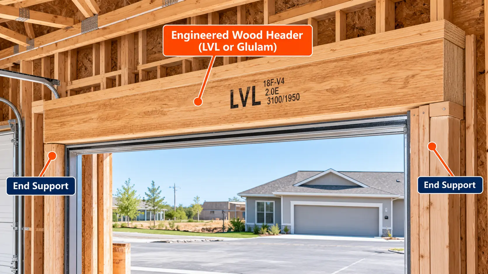
Laminated veneer lumber (LVL) is a common engineered alternative. Its design values come from the specific product, not from the IRC sawn-lumber tables. Manufacturer span tables or an engineered design give the allowable spans, bearing requirements and fastening for multiple plies. Moisture and service conditions also apply, so always work from current product documentation.
LVL commonly comes about 1-3/4 in. thick in a range of depths. A nominal 1-3/4 in.-thick LVL is not automatically interchangeable with a 1-1/2 in. sawn-lumber ply. For that reason, do not use substitutions such as “(2) 2×12 equals (2) 1-3/4 × 11-7/8 LVL.” The materials have different properties and need product-specific evaluation.
Where to Go Next
For span tables and sizing context on engineered products, use the LVL Span Chart, and for wide openings or point loads compare the Wood Beam Span Chart. Neither replaces the manufacturer’s tables for a specific product.
Glulam and Other Engineered Header Alternatives
When a wide opening or heavy load goes beyond dimensional lumber.
Glued-laminated timber (glulam) is another engineered header option. APA publishes structural glulam design resources, and designing with glulam involves checks for bending, shear and deflection. Compared with built-up lumber, glulam comes in stress classes and species with different design properties, in a range of depths and widths, and with its own bearing and connection requirements.
Other engineered alternatives include parallel strand lumber (PSL), laminated strand lumber (LSL) and steel. Each is sized from manufacturer tables or an engineered design. Keep detailed glulam sizing on the Glulam Beam Size Chart, and use the Beam Size Calculator only as a starting point for beams that support joists.
Jack Studs vs. King Studs
NJ counts jack studs, not every stud beside the opening.
Three types of studs appear around an opening, and the code treats them differently.
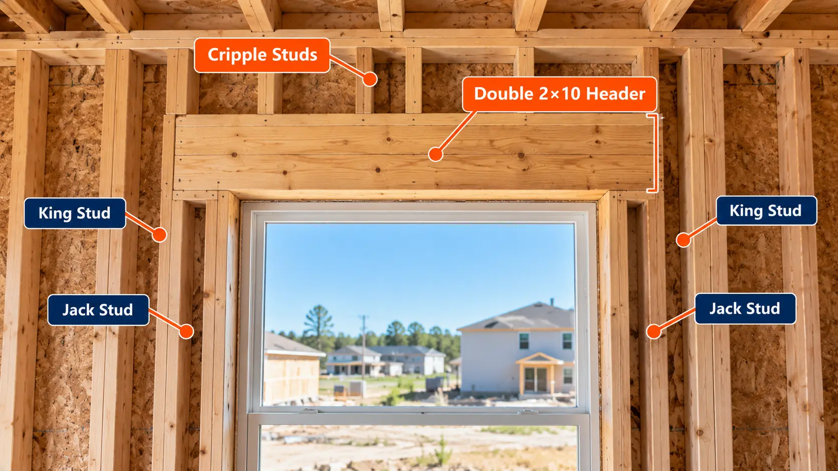
| Stud | Location | Role |
|---|---|---|
| Jack stud (trimmer) | Directly under each header end | Provides bearing support for the header |
| King stud (full-height stud) | Beside the jack studs, full wall height | Stabilizes the opening and joins the wall framing and load path |
| Cripple stud | Above or below the opening | Short stud where framing is needed above or below |
The tables report jack studs only. NJ is the number of jack studs required at each end of the header, and it is read from the same cell as the span. Where the cell lists one jack stud, an approved framing anchor can be used in its place under the table note. The full-height stud count comes from a separate section, so NJ is not the total number of studs at each jamb.
Minimum Full-Height Stud Requirements
Table R602.7.5 and the wind conditions behind it.
Section R602.7.5 requires headers to be supported at each end by jack studs or approved framing anchors per the tables, with the full-height stud adjacent to each end of the header end nailed to the header. Table R602.7.5 then sets the minimum number of full-height studs at each end of headers in exterior walls. The count depends on the maximum header span, the ultimate design wind speed and the exposure category.
For illustration, published summaries of the table show that for the typical 115 mph or lower, Exposure B column, a span of 4 through 8 ft needs 1 full-height stud at each end and spans of 10 ft and up need 2, while the higher-wind column needs between 2 and 4 depending on span. The same header span therefore needs different support depending on the wind and exposure column, so read your exact row and column in the adopted edition.
| Factor | Effect on the table result |
|---|---|
| Maximum header span | Longer spans need more full-height studs |
| Ultimate design wind speed | Higher wind speed columns need more studs |
| Exposure category | More exposed sites need more studs |
| Framing anchor in place of a jack stud | Follows the below-140-mph, Exposure B requirement |
Scope Matters
The tabulated count applies where jack studs are provided at each end per Table R602.7(1). Do not read “one jack stud” as “one supporting stud,” and do not use the full-height stud table without its wind and exposure scope.
Header Bearing and Structural Load Path
Why the supports matter as much as the header.
A header can be adequate in bending and still fail because the support is inadequate. The load path runs from the header into its supports, down through the bottom plate and subfloor framing, and into the foundation. Bearing area, compression perpendicular to grain, jack-stud load transfer, concentrated loads and connections all take part.
An adequate header does not equal an adequate entire opening assembly. For posts and columns that receive concentrated loads below, see the Column Size Chart, and for beams that collect loads from above, see the Wood Beam Span Chart.
Header Lateral Bracing and the IRC 0.70 Factor
The footnote that many generic header charts leave out.
The IRC header spans assume the top of the header or girder is laterally braced by perpendicular framing, such as floor joists, ceiling joists or trusses attached to the top plate. Where that bracing is absent, for example when cripple studs bear on the header, the tabulated spans for 2×8, 2×10 and 2×12 headers must be multiplied by 0.70, or the header must be designed.
🧮 Unbraced Header Span Adjustment
Variables: Ltable = tabulated span (in.), Ladjusted = reduced span (in.). It applies only to the 2×8, 2×10 and 2×12 sizes and only under the table’s stated conditions.
Applying the 0.70 Factor
What it means: Do not apply the factor outside the table conditions, and do not assume simple multiplication finishes the design. Jack studs, full-height studs and bearing still have to be checked.
Header Size for Doors
Why no door width gives one header size.
Door headers depend on whether the wall is bearing, which wall it is in, and the loads above, not on the door width alone. No generic statement such as “a 36-inch door always needs a double 2×6” is reliable.
- Door size and rough opening: take the rough opening from the door manufacturer. See the Door Rough Opening Chart.
- Load-bearing status: an interior door in a nonbearing partition follows the nonbearing rule, while an exterior door in a bearing wall follows Table R602.7(1).
- Exterior vs. interior wall: use the matching IRC table.
- Jamb support: jack studs and full-height studs carry the header ends.
- Headroom and tolerances: header depth affects clear height, and installation tolerances need their own allowance.
To compare a door opening quickly, try the Door Header Size Calculator.
Header Size for Windows
Rough opening, structural span and building width all play a part.
Window headers follow the same logic. Exterior walls with window openings are usually bearing walls, so the table is entered by the loads the wall supports, the building width and the snow load.
- Rough opening vs. structural span: the manufacturer sets the rough opening, and the header must clear the structural span between supports. See the Window Rough Opening Chart.
- Exterior bearing walls, snow and building width: these decide the tabulated span.
- Jamb and sill framing: king studs, jack studs, the sill and cripple studs where needed frame the opening.
- Movement: allow for installation movement and deflection under the header.
Garage Door Header Sizes
Wide openings usually leave the prescriptive tables.
Garage door openings are among the most searched header questions, and they are also the ones most likely to leave the prescriptive tables. A 9-ft opening and a 16-ft opening cannot be sized from opening width alone.
- Wide opening: long spans increase bending, shear and deflection demand quickly.
- Concentrated loads: girders, posts or beam ends landing on the header fall outside the tables.
- Supports: jack studs, full-height studs and the connections between them matter more at wide openings.
- Wind and lateral framing: large openings interact with wall bracing, so check the wall bracing requirements.
- Manufacturer clearances: the garage door maker sets headroom and mounting requirements.
For wide openings, unusual load paths or conditions beyond the scope of the code tables, an engineered design may be required. Engineered LVL, glulam or steel headers are the normal path, selected for the actual loads. Compare options in the LVL Span Chart and Glulam Beam Size Chart, and check the load path with the Live and Dead Load Calculator.
Porch Header Size Requirements
Table R602.7(3) has its own conditions.
IRC Table R602.7(3) covers open porches. Its columns distinguish whether the header or beam supports a roof or a floor, the porch depth and the ground snow load. These are different conditions from a conventional exterior bearing-wall header.
Do Not Substitute Table Results
Do not use porch table results for a standard exterior bearing-wall header, or the reverse. Each table has its own load basis. For beams in other locations, see the Beam Size Chart.
Header Loads, Bending, Shear and Deflection
A simplified look at how load becomes bending, reaction and deflection.
The formulas below are simplified teaching tools. They explain how loads, bending, reactions and deflection scale, but they do not size a real header.
🧮 Formula 1: Uniform Load
Variables: w = uniform line load (plf), q = surface load (psf), T = contributing tributary width (ft). This is a teaching model, not an IRC snow-load conversion.
Illustrative Header Load, Moment, Reaction and Stress
What it means: The 720 lb reaction is not a jack-stud design load, and 493 psi is not a code check. Real design adjusts lumber values and also checks shear, deflection, bearing, connections and stability.
🧮 Formula 2: Deflection
Variables: w in lb/in., L in inches, E in psi, I in in4. Because L enters to the fourth power, a longer opening produces a much greater deflection demand under the idealized relationship, with all else equal. Do not turn this formula into a universal header calculator.
For deflection concepts, see the Beam Deflection Chart and the Beam Deflection Calculator.
How to Choose the Correct Header Size
A decision sequence instead of a one-column table.
- Determine whether the wall is bearing or nonbearing. Never guess from interior or exterior location alone.
- Identify the opening. Door, window or garage opening, the manufacturer rough opening and the structural header span.
- Identify the supported loads. Roof and ceiling only, with one or two floors, interior floors, a porch roof or floor, and any concentrated loads.
- Determine building width and snow conditions. Use the variables as the selected IRC table defines them.
- Choose the correct IRC table. R602.7(1) exterior bearing, R602.7(2) interior bearing, R602.7(3) open porch, or an alternative assembly section.
- Select a candidate. Member depth, number of plies, species and grade, and material type.
- Verify the maximum span. Use the exact row and column.
- Verify jack studs and full-height studs. Do not ignore the support requirements.
- Verify bracing and connections. Lateral restraint, framing connections, bearing and the load path.
- Check for engineered-design conditions. Ask the building department or a design professional when the opening exceeds the prescriptive limits or loading is unusual.
Worked Selection Example
Suppose an exterior bearing wall supports roof and ceiling only, the building is 24 ft wide, ground snow is 30 psf and the opening needs a 5′-6″ header span, with the prescribed species, grade and bracing conditions met.
| Candidate | Tabulated span | Meets 5′-6″ span? | Jack studs per end |
|---|---|---|---|
| (2) 2×6 | 4′-7″ | No | 1 |
| (2) 2×8 | 5′-9″ | Yes, by tabulated span | 1 |
| (2) 2×10 | 6′-10″ | Yes, by tabulated span | 2 |
Interpret Cautiously
The double 2×8 meets the span comparison under the listed conditions, with the table’s jack studs. That does not finish the design. The adopted code must match, the actual loads and building width must be confirmed, bracing must be established, the jack and full-height studs must satisfy their provisions, bearing and connections must be adequate, and unusual loads may call for engineered design. For a quick estimate, try the Door Header Size Calculator or the Framing Calculator, then confirm against the code tables.
Common Header Sizing Mistakes
The errors that cause the most trouble when people pick a header size.
Sizing from opening width alone
Selecting a header from the opening width alone, calling every double 2×8 suitable for a 6-ft opening, or using a generic online chart without stated assumptions.
Confusing building width and opening size
Mixing up building width with opening width, and rough opening with header cut length.
Ignoring wall classification
Skipping the bearing classification, using exterior-wall tables for interior bearing walls, or applying nonbearing-header rules to bearing walls.
Ignoring what the header supports
Using roof-only values when a floor is supported, or ignoring the number of supported floors and any concentrated loads.
Snow load errors
Ignoring ground snow load, or confusing ground snow load with roof snow load.
Ignoring the lumber
Ignoring the actual species and grade, using nominal size in calculations, or confusing header depth with built-up width.
Ignoring bracing
Ignoring lateral-bracing conditions or forgetting the 0.70 factor where it applies.
Support mistakes
Omitting required jack studs, confusing jack studs with full-height studs, or assuming one jack stud means one total stud.
Skipping wind requirements
Ignoring wind-related full-height stud requirements in Table R602.7.5.
Weak load path
Ignoring bearing on the supporting framing, or assuming added plies automatically solve every design issue.
Built-up assembly errors
Assuming spacer material adds capacity, or installing improperly fastened built-up plies.
Engineered wood substitutions
Substituting LVL without product-specific sizing, or assuming engineered wood is interchangeable with sawn lumber.
Altering a bearing wall
Removing bearing-wall studs without temporary support and an alteration plan, or cutting a large opening without evaluating the load path.
Mixing up headers, beams and garages
Confusing header size with beam size, or using garage-header advice for ordinary door openings.
Treating simple math as compliance
Ignoring shear, bending, deflection or compression perpendicular to grain, or treating a simplified beam calculation as full code compliance.
Skipping local code
Ignoring the locally adopted code edition and amendments.
Header Size FAQs
Straight answers to the questions people ask most about header sizes.
What is a standard header size?
No single header size is standard. Common built-up headers are two plies of 2×6, 2×8, 2×10 or 2×12 lumber, and the right one depends on the wall, loads, building width, snow load and opening span.
What size header do I need?
Decide whether the wall is bearing, identify the supported loads, building width and snow load, pick the matching IRC table, and read the exact row and column. Then check jack studs, full-height studs, bracing and connections.
What size header for a 3-foot opening?
Under one verified set of conditions (exterior bearing wall, roof and ceiling only, 24-ft building, 30 psf ground snow, braced top) a double 2×4 is tabulated to 3′-1″ with 1 jack stud per end. A floor above, heavier snow or a wider building changes that, so check the Header Span Chart.
What size header for a 4-foot opening?
Under one verified set of conditions (exterior bearing wall, roof and ceiling only, 24-ft building, 30 psf ground snow, braced top) a double 2×6 is tabulated to 4′-7″ with 1 jack stud per end. Other conditions give different answers.
What size header for a 5-foot opening?
Under one verified set of conditions (exterior bearing wall, roof and ceiling only, 24-ft building, 30 psf ground snow, braced top) a double 2×8 is tabulated to 5′-9″ with 1 jack stud per end. Other conditions give different answers.
What size header for a 6-foot opening?
Under one verified set of conditions (exterior bearing wall, roof and ceiling only, 24-ft building, 30 psf ground snow, braced top) a double 2×10 is tabulated to 6′-10″ with 2 jack studs per end, while a double 2×8 falls short at 5′-9″. Other conditions give different answers.
What size header for an 8-foot opening?
Under one verified set of conditions (exterior bearing wall, roof and ceiling only, 24-ft building, 30 psf ground snow, braced top) a double 2×12 is tabulated to 8′-1″ with 2 jack studs per end. Wider buildings, snow or floors above can rule that out.
What size header for a 10-foot opening?
A 10-ft opening is beyond the double-header values in the verified example. Check the triple and quadruple rows for your exact conditions in the Header Span Chart, or have the header engineered.
What size header for a 12-foot opening?
A 12-ft opening usually needs a designed header, such as LVL or glulam, or a carefully checked row from the code table. It cannot be sized from width alone.
What size header for a 16-foot garage door?
A 16-ft garage door opening generally needs an engineered header selected for the actual loads, such as LVL, glulam or steel, with proper end supports.
Can a double 2×6 be used as a header?
Yes, where the applicable IRC table allows it. In the verified example (24-ft building, 30 psf snow, roof and ceiling only) it is tabulated to 4′-7″ with 1 jack stud per end.
How far can a double 2×8 header span?
Under roof and ceiling only and 30 psf ground snow, it is tabulated to 7′-7″ in a 12-ft building, 5′-9″ in a 24-ft building and 4′-10″ in a 36-ft building. Other conditions change it. See the Header Span Chart.
How far can a double 2×10 header span?
In the verified example it is tabulated to 6′-10″ with 2 jack studs per end. Building width, snow, supported floors and bracing change that. See the Header Span Chart.
How far can a double 2×12 header span?
In the verified example it is tabulated to 8′-1″ with 2 jack studs per end. Other conditions change it, so use the Header Span Chart for the exact row.
Is a double 2×10 stronger than a double 2×8?
Geometrically it has about 2.08 times the moment of inertia and about 1.63 times the section modulus. Real capacity also depends on species, grade, loads, bracing and supports, so do not read those ratios as span or load ratios.
How many jack studs does a header need?
The IRC span tables list the jack studs required at each end (NJ) for each cell, such as 1 for a double 2×8 and 2 for a double 2×10 in the verified example. The number changes with header size, supported loads, building width and snow load.
How many king studs do I need?
King studs are not counted by the NJ column. The minimum number of full-height studs comes from Table R602.7.5 and depends on header span, wind speed and exposure.
Does a nonbearing wall need a header?
A load-bearing header is not required in a nonbearing wall. Under specific conditions a single flat 2×4 can be used for an opening up to 8 ft where the distance to the nailing surface above is 24 in. or less.
Can I use a flat 2×4 header in a nonbearing wall?
Yes, under the conditions in IRC Section R602.7.4: an opening up to 8 ft and no more than 24 in. to the parallel nailing surface above. Do not use it in a bearing wall.
What is the difference between a king stud and a jack stud?
A jack stud sits directly under the header end and provides bearing. A king stud runs full height beside the jack stud and helps tie the opening into the wall framing.
What is the difference between a header and a beam?
A header carries loads over a wall opening into jack studs, while a beam carries loads over a longer span to posts or walls. Header tables do not size beams. See the Beam Size Chart.
Can I use LVL instead of dimensional lumber?
Often yes, but only with product-specific sizing from the manufacturer or an engineer. LVL is not a one-for-one substitute for sawn-lumber plies.
Can a header be made from three 2×8 boards?
Yes. A three-ply 2×8 header is 4.5 in. wide and 7.25 in. deep, and the IRC tables list built-up headers up to four plies. It must still be sized from the correct table and fastened properly.
Can I use plywood spacers between header plies?
A spacer, such as 1/2 in. material, can help match wall thickness, and the IRC fastening table covers a two-ply header with a spacer. A spacer does not add structural capacity.
Does snow load change header size?
Yes. In the verified example, a double 2×8 drops from 5′-9″ at 30 psf to 5′-0″ at 50 psf and 4′-5″ at 70 psf, and needs 2 jack studs instead of 1.
Does building width affect header span?
Yes. A double 2×8 is tabulated to 7′-7″, 5′-9″ and 4′-10″ in 12-, 24- and 36-ft buildings under the same roof-and-ceiling, 30 psf conditions.
Does header size change between one- and two-story houses?
Yes. A header that supports a floor carries more load, so use the row for the exact number and type of floors supported.
What is the required bearing length for a header?
There is no universal value. Bearing depends on the header, the jack studs and the support design, so follow the applicable code provisions or the engineered design.
Do headers need lateral bracing?
The IRC tables assume the header top is laterally braced. Without that bracing, spans for 2×8, 2×10 and 2×12 headers are multiplied by 0.70, or the header must be designed.
What does NJ mean in an IRC header table?
NJ is the number of jack studs required at each end of the header.
What is the maximum span of a single-member header?
It depends on the IRC table row and the code assembly for single-member headers in R602.7.1. Do not treat a single member as equal to a double 2× header.
Can I remove studs to enlarge a door opening?
Not without checking the load path. If the wall is bearing, the opening needs a properly sized header, supports and temporary shoring during the work, plus any required permit.
Cite or Embed This Chart
📄 Print or Save This Chart as PDF
Use your browser’s print function to save the page as a PDF reference for jobsite binders and estimating folders.
Sources and Standards Used
Header spans, jack stud counts and provisions come from the IRC header tables and sections listed below. Table values shown match the 2021 edition and are reported unchanged in the 2024 edition, so confirm the table in the edition and local amendments adopted in your jurisdiction. Section properties, tributary loads, moments and bending stress are calculated from the formulas shown and are marked as derived.