Framing Nail Size Chart – Lengths, Diameters and Code Requirements
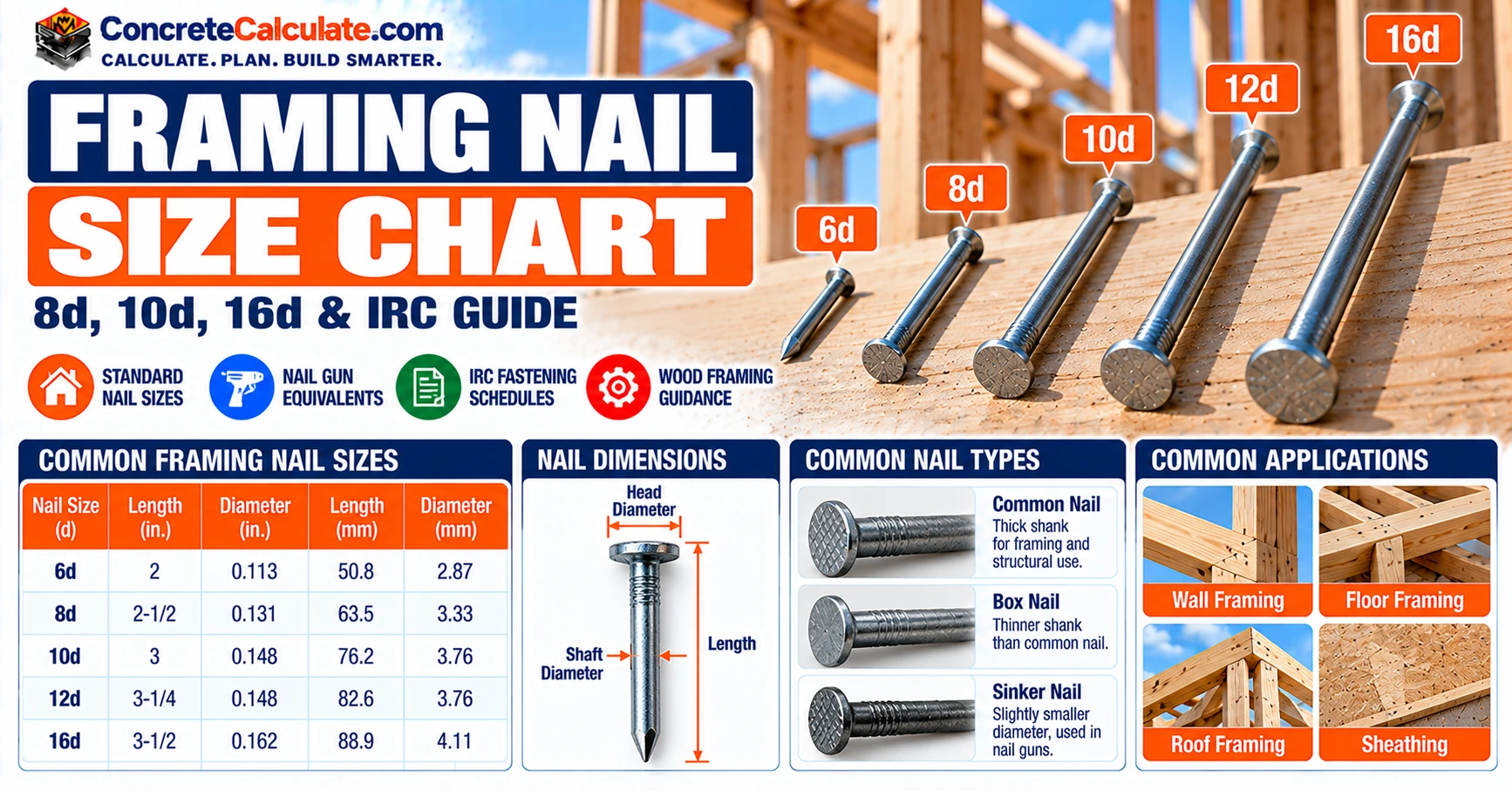
Framing Nail Size ChartLengths, Diameters and Code Requirements
A practical reference for carpenters, framers, inspectors and DIY builders: penny sizes, actual nail lengths and shank diameters, nail-gun equivalents and selected 2024 IRC fastening schedule entries.
Jump to the Chart Reviewed by Muhammad Ramzan Babar, PhD Researcher (Plasma Physics) & Calculator Developer, View Profile
Key Facts
- 8d common: 2-1/2 in. × 0.131 in. 10d common: 3 in. × 0.148 in. 16d common: 3-1/2 in. × 0.162 in.
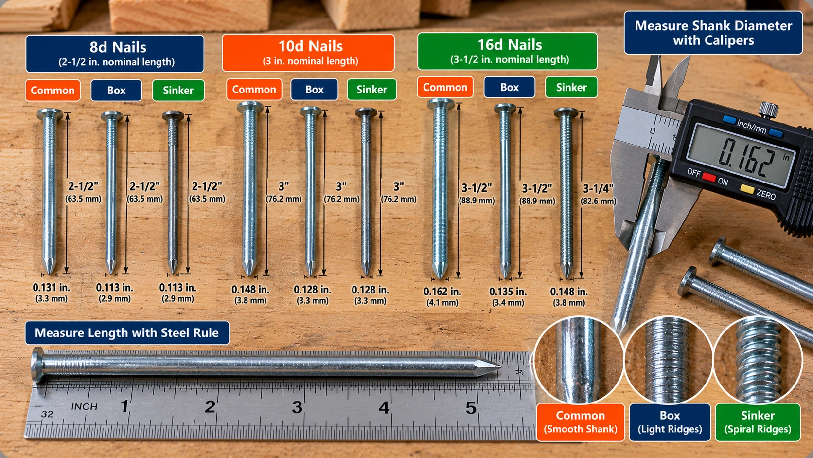
- An 8d, 10d or 16d label does not fix a nail’s dimensions. Box and sinker nails with the same label are thinner, and sinkers can be shorter.
- Always identify a framing nail by length, shank diameter and type, and use the exact nail the code row or plan lists.
Framing Nail Size Chart: Quick Reference
Penny size, length, diameter and nail type for the framing nails most often specified in the U.S.
How to Read This Chart
Find the penny size in the first column, then read across for the length and shank diameter of each nail family. Box nails are the same length as common nails but thinner. Sinker nails can be both shorter and thinner. All diameters are nominal shank diameters in inches. For the full penny-size system and non-framing nails, see the general Nail Size Chart.
| Penny size | Common length (in.) | Common shank dia. (in.) | Box shank dia. (in.) | Sinker length (in.) | Sinker shank dia. (in.) |
|---|---|---|---|---|---|
| 6d | 2 | 0.113 | 0.099 | 1-7/8 | 0.092 |
| 7d | 2-1/4 | 0.113 | 0.099 | 2-1/8 | 0.099 |
| 8d | 2-1/2 | 0.131 | 0.113 | 2-3/8 | 0.113 |
| 10d | 3 | 0.148 | 0.128 | 2-7/8 | 0.120 |
| 12d | 3-1/4 | 0.148 | 0.128 | 3-1/8 | 0.135 |
| 16d | 3-1/2 | 0.162 | 0.135 | 3-1/4 | 0.148 |
| 20d | 4 | 0.192 | 0.148 | 3-3/4 | 0.177 |
- The penny size alone does not establish code compliance. The IRC lists nails by quantity, length and shank diameter for each connection.
- Pneumatic (nail-gun) nails are identified by exact diameter × length, such as 3 in. × 0.131 in., and are covered separately below.
- This chart is a dimensional reference, not a fastening schedule. Rows shaded orange (8d, 10d and 16d) are the sizes most often called out in residential framing.
Dimensions: Simpson Strong-Tie nail reference, which cites the AWC NDS (Appendix L) and ASTM F1667. Head diameters and metric conversions follow in the length and diameter section.
What Is a Framing Nail?
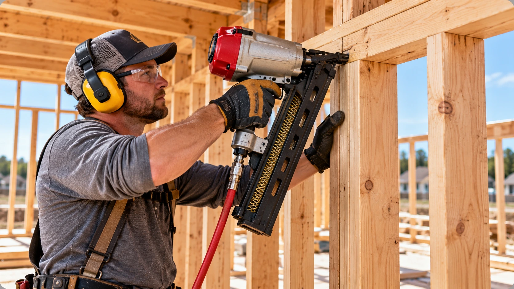
A framing nail is a driven fastener used to assemble the wood members of a building frame: studs, plates, headers, joists, rafters, blocking and sheathing. Framing nails are driven by hammer or by a pneumatic or cordless framing nailer. They are heavier than finish nails, brads and staples, and they are chosen by length, shank diameter and head, not only by a trade label.
Framing Nail Types
- Common nails: the heavier-shank nail that the IRC often uses as its reference dimension.
- Box nails: same length as common, thinner shank, often with a coating for easier driving.
- Sinker nails: a coated nail that is usually shorter and thinner than the matching common nail; a 16d sinker is 3-1/4 in. × 0.148 in.
- Connector nails: shorter, specified nails made for metal hangers, straps and ties.
Hand-Driven vs. Pneumatic Nails
Hand-driven nails are sold loose by penny size and type. Pneumatic framing nails are collated into strips or coils and are sold by diameter, length, head style and the angle of the tool they fit. Finish nails, brads, roofing nails and staples are different products with different jobs, and they stay on the general nail chart.
Framing Nail Standards and Building Codes
2024 IRC Fastening Schedule
Section R602.3 of the 2024 International Residential Code requires wood wall components to be fastened in accordance with its tables. Table R602.3(1) is the main fastening schedule. Each row names a framing connection, the number and type of nails, and the spacing or method (face nail, end nail or toe nail). Where several alternatives are listed, they are alternatives for that row only.
Footnotes to the table also set a minimum nail bending yield strength: 80 ksi for a 0.192 in. shank (20d common), 90 ksi for shanks larger than 0.142 in. up to 0.177 in., and 100 ksi for shanks of 0.142 in. or less. Nails of other materials, such as stainless steel, must be designed by accepted engineering practice or approved by the building official.
ASTM F1667
ASTM F1667/F1667M covers driven fasteners (nails, spikes and staples), including types, dimensions, tolerances, materials and coatings. The AWC National Design Specification requires nails to comply with it, and the NDS summarizes the structural nail dimensions in Appendix L.
AWC NDS and APA Guidance
The 2024 NDS gives the engineering method for nail withdrawal and lateral resistance. APA publishes panel installation and fastening guidance for roof, wall and floor sheathing. Use the NDS for engineered connections and the panel manufacturer or APA documents for panel-specific details.
Edition and Local Adoption
The 2024 IRC is a reference edition, not proof of nationwide adoption. The locally adopted code and amendments, the approved plans and the product requirements control the job.
Understanding Framing Nail Penny Sizes
The penny system is a traditional length designation. The letter d comes from the Latin denarius, and a larger number means a longer nail. It does not specify shank diameter, head, coating or point, so two nails with the same penny size can differ in strength and fit.
What 8d, 10d and 16d Mean
- 8d common: 2-1/2 in. × 0.131 in.
- 10d common: 3 in. × 0.148 in.
- 16d common: 3-1/2 in. × 0.162 in.
Penny Size vs. Actual Dimensions
Simpson Strong-Tie recommends calling out a nail by diameter and length to avoid confusion. A framer who asks for “16d nails” may receive a 16d box nail (0.135 in.) or a 16d sinker (3-1/4 in. long), neither of which equals a 16d common. For the complete penny-size ladder, including the long spikes, use the general Nail Size Chart.
Framing Nail Length and Diameter Chart
Standard Dimensions
The main chart above gives the lengths and shank diameters. Shank diameter matters as much as length: a 0.131 in. nail has about 34% more shank cross-section than a 0.113 in. nail of the same length, which is why the IRC lists box and common nails with different quantities.
Metric Conversions
Inch to Millimeter Conversion
Variables: in. = nail length or shank diameter in inches; mm = the same dimension in millimeters
Practical interpretation: The conversions are nominal values for reference. Manufactured nails carry tolerances set in ASTM F1667, so measured values can differ slightly.
| Common nail | Length (in.) | Length (mm) | Shank dia. (in.) | Shank dia. (mm) |
|---|---|---|---|---|
| 6d | 2.00 | 50.80 | 0.113 | 2.87 |
| 8d | 2.50 | 63.50 | 0.131 | 3.33 |
| 10d | 3.00 | 76.20 | 0.148 | 3.76 |
| 12d | 3.25 | 82.55 | 0.148 | 3.76 |
| 16d | 3.50 | 88.90 | 0.162 | 4.11 |
| 20d | 4.00 | 101.60 | 0.192 | 4.88 |
Shank and Head Size
Head diameter affects pull-through resistance and whether a nail fits a given tool. The IRC sheathing rows even list head diameters, such as 0.266 in. and 0.281 in. Values below are the nominal heads for full-round-head hand nails.
| Penny size | Common head | Box head | Sinker head |
|---|---|---|---|
| 6d | 0.266 | 0.266 | 0.234 |
| 7d | 0.266 | 0.266 | 0.250 |
| 8d | 0.281 | 0.297 | 0.266 |
| 10d | 0.312 | 0.312 | 0.281 |
| 12d | 0.312 | 0.312 | 0.312 |
| 16d | 0.344 | 0.344 | 0.344 |
| 20d | 0.406 | 0.375 | 0.375 |
Head diameters per Simpson Strong-Tie (citing NDS Appendix L and ASTM F1667). Simpson’s collated connector nails carry a 0.285 in. head for 8d, 10d and 16d sizes.
Common vs. Box vs. Sinker Framing Nails
The three families are separate products, and the code treats them that way. Look at the 16d row: the box nail is the same length as the common nail but about 31% smaller in shank cross-section, and the sinker is 1/4 in. shorter as well.
| Nominal size | Common nail | Box nail | Sinker nail |
|---|---|---|---|
| 8d | 2-1/2 × 0.131 | 2-1/2 × 0.113 | 2-3/8 × 0.113 |
| 10d | 3 × 0.148 | 3 × 0.128 | 2-7/8 × 0.120 |
| 16d | 3-1/2 × 0.162 | 3-1/2 × 0.135 | 3-1/4 × 0.148 |
Dimensional Differences
| Comparison | Shank dia. (in.) | Smaller shank area |
|---|---|---|
| 8d box vs 8d common | 0.113 vs 0.131 | 26% |
| 8d sinker vs 8d common | 0.113 vs 0.131 | 26% (and 1/8 in. shorter) |
| 10d box vs 10d common | 0.128 vs 0.148 | 25% |
| 10d sinker vs 10d common | 0.120 vs 0.148 | 34% (and 1/8 in. shorter) |
| 16d box vs 16d common | 0.135 vs 0.162 | 31% |
| 16d sinker vs 16d common | 0.148 vs 0.162 | 17% (and 1/4 in. shorter) |
Code Recognition
Table R602.3(1) lists nail types by name and dimension in each row, and it often gives alternatives that offset the thinner shank with more nails or tighter spacing. For example, a built-up 2-inch header with a 1/2 in. spacer takes a 16d common nail at 16 in. on center along each edge, or a 16d box nail at 12 in. on center. A continuous header to stud toe-nail connection takes four 8d common nails, or five 8d box nails, or four 10d box nails.
Substitution Limitations
Thinner Does Not Mean Equivalent
A box or sinker nail is not a drop-in replacement for a common nail. Use the exact nail and quantity listed for that row, and do not assume that adding extra thin nails automatically restores capacity unless the schedule says so.
8d Framing Nail Size and Uses
8d is the small framing nail. The IRC uses it for toe-nailing and for roof sheathing, where a long nail is not needed.
8d Common
2-1/2 in. long with a 0.131 in. shank and a 0.281 in. head.
8d Box and Sinker
The 8d box nail is 2-1/2 in. × 0.113 in. and the 8d sinker is 2-3/8 in. × 0.113 in. The IRC lists 8d box nails in several rows with a higher count than 8d common, for instance five 8d box nails where four 8d common are listed for a continuous header toe-nail connection.
Framing Applications
| Connection (2024 IRC Table R602.3(1)) | Listed fastening | Method |
|---|---|---|
| Continuous header to stud | 4-8d common (2-1/2 × 0.131) | Toe nail |
| Top or bottom plate to stud | 4-8d common (2-1/2 × 0.131) | Toe nail |
| Ceiling joists to top plate | 3-8d common (2-1/2 × 0.131) per joist | Toe nail |
| Bridging or blocking to joist, rafter or truss | 2-8d common (2-1/2 × 0.131) at each end | Toe nail |
| Roof sheathing, 3/8 in. to 3/4 in. panels | 8d common (2-1/2 × 0.131 × 0.281 head) | Edge and intermediate nailing |
Selected rows only. Each row has alternatives and footnotes, so 8d is not assigned to one use everywhere.
10d Framing Nail Size and Uses
10d sits between the small and large framing nails. It appears in both its common and box forms in the IRC schedule.
10d Common
3 in. long with a 0.148 in. shank and a 0.312 in. head.
10d Box and Sinker
The 10d box nail is 3 in. × 0.128 in. and the 10d sinker is 2-7/8 in. × 0.120 in.
IRC Alternatives
The IRC also lists a dimensionally specified 3 in. × 0.131 in. nail in many rows, usually beside 10d box. A 3 in. × 0.131 in. nail is not the same as a 10d common nail (3 in. × 0.148 in.), and it is accepted only where the row names it.
| Connection (2024 IRC Table R602.3(1)) | Listed fastening | Method |
|---|---|---|
| Stud to stud, not at braced wall panels | 10d box (3 × 0.128) or 3 × 0.131 nails, 16 in. o.c. | Face nail |
| Top plate to top plate | 10d box (3 × 0.128) or 3 × 0.131 nails, 12 in. o.c. | Face nail |
| Rafter or roof truss to plate | 3-10d common (3 × 0.148), 2 toe nails on one side and 1 on the other | Toe nail |
| Collar tie to rafter | 3-10d common (3 × 0.148) at each rafter | Face nail |
| Roof sheathing, 7/8 in. to 1-1/4 in. panels | 10d common (3 × 0.148) at 6 in. edges, 12 in. intermediate | Edge and intermediate nailing |
16d Framing Nail Size and Uses
16d is the large framing nail and the one most people picture when they say “framing nail.” It is also the nail most often mislabeled.
16d Common
3-1/2 in. long, 0.162 in. shank and a 0.344 in. head.
16d Box and Sinker
The 16d box nail is 3-1/2 in. × 0.135 in. and the 16d sinker is 3-1/4 in. × 0.148 in. A 3-1/4 in. nail should never be described as a 3-1/2 in. 16d common nail.
Framing Connections
| Connection (2024 IRC Table R602.3(1)) | Listed fastening | Method |
|---|---|---|
| Stud to stud, not at braced wall panels | 16d common (3-1/2 × 0.162), 24 in. o.c. | Face nail |
| Top or bottom plate to stud | 2-16d common (3-1/2 × 0.162) | End nail |
| Double top plate splice | 8-16d common each side of end joint, 24 in. minimum lap each side | Face nail |
| Adjacent full-height stud to end of header | 3-16d common (3-1/2 × 0.162) | End nail |
| Band or rim joist to joist | 3-16d common (3-1/2 × 0.162) | End nail |
| 2 in. subfloor to joist or girder | 2-16d common (3-1/2 × 0.162) | Blind and face nail |
Pneumatic Framing Nail Size Chart
Collated framing nails are sold by exact size rather than penny label. Most full-size framing nailers drive nails from roughly 2 in. to 3-1/2 in. long, but the supported length and diameter range depends on the tool model, so check the nailer manual.
Common Nail-Gun Lengths
| Nail specification | Nominal length (in.) | Shank dia. (in.) | Interpretation |
|---|---|---|---|
| 2 × 0.113 | 2 | 0.113 | Appears in IRC sheathing rows for 3/8 in. to 1/2 in. wall and subfloor panels; check the row |
| 2-3/8 × 0.113 | 2-3/8 | 0.113 | Matches 8d sinker dimensions; the IRC roof sheathing ring-shank nail (RSRS-01) uses this size |
| 2-1/2 × 0.131 | 2-1/2 | 0.131 | Matches 8d common |
| 3 × 0.131 | 3 | 0.131 | Named as an alternative in many IRC fastening rows |
| 3 × 0.148 | 3 | 0.148 | Matches 10d common |
| 3-1/4 × 0.148 | 3-1/4 | 0.148 | Matches 16d sinker |
| 3-1/2 × 0.162 | 3-1/2 | 0.162 | Matches 16d common |
Shank Diameters
Typical collated framing nails have 0.113 in., 0.120 in., 0.131 in., 0.148 in. and 0.162 in. shanks. A thinner gun nail needs the quantity or spacing listed for that diameter, not the quantity listed for a common nail.
Code-Compatible Alternatives
The 2024 IRC names 3 in. × 0.131 in. nails in many rows, so that size is widely used. Nails sold as 3-1/4 in. × 0.131 in. are common in the market, but the IRC rows name 3 in. × 0.131 in., so a longer nail of that diameter is not a listed alternative unless the code or an approval says so.
Dimensional Match Is Not Equivalence
Verify head shape, shank type, nail bending properties, tool compatibility, installation conditions and code acceptance before treating a gun nail as a hand-driven nail.
Framing Nailer Angles and Collation
The angle of a framing nailer describes the magazine, not the strength of the nail. A nail can fit a tool and still fail to match the connection’s fastening schedule, and the reverse is also true.
| Nailer category | Common collation format | Main consideration |
|---|---|---|
| 15° | Wire-collated coil | Many 15° coil tools are siding, fencing or pallet models; confirm the tool is rated for framing nails |
| 21° | Plastic-collated strip | Commonly used with full-round-head nails; check the tool manual for head style |
| 28° | Wire-collated strip | Check which head styles the tool accepts |
| 30° | Paper-collated strip | Verify tool and nail specifications |
| 34° | Paper-collated strip | Verify head style and tool compatibility |
21° and 28° Nailers
21° tools use plastic-collated strips, usually with full-round-head nails. 28° tools use wire-collated strips. Both are common in residential framing.
30° and 34° Nailers
30° and 34° tools use paper-collated strips. The tighter angle holds more nails per strip and lets the tool reach into closer corners, and these tools are often paired with clipped or offset heads.
Magazine Compatibility
Wire, plastic and paper strips are not interchangeable between tools. Match the magazine angle, collation type, length range and shank diameter in the owner’s manual of your specific nailer.
Angle Is Not a Structural Rating
No magazine angle is universally code-approved or stronger than another. Only the nail’s dimensions, head, shank and the fastening schedule matter for structural performance.
Full-Round-Head vs. Clipped-Head Framing Nails
Head shape determines the bearing area under the nail and how well the nail resists pulling through the wood or sheathing.
Head Geometry
A full-round head is a complete disc, such as the 0.344 in. head on a 16d common nail. Clipped-head (also called D-head) and offset-head nails trim or shift part of the head so the nails can sit closer together in the strip. Less head area means less bearing area at the same shank size.
Code and Product Approval
Neither style is universally prohibited or universally accepted. Some clipped-head products carry an ICC-ES evaluation for use under the IBC and IRC, and engineered shear-wall and diaphragm designs may list the head diameter they require. Some jurisdictions or engineers also restrict them. Check the adopted code, the nail’s evaluation report and the approved plans.
Nail-Gun Compatibility
Many 21° tools take full-round-head nails, while 28°, 30° and 34° tools often take clipped or offset heads. The tool manual lists what it accepts.
Smooth-Shank vs. Ring-Shank vs. Screw-Shank Nails
| Shank | Description | Withdrawal behavior | Typical use |
|---|---|---|---|
| Smooth | No deformations; easiest to drive | Least pull-out resistance of the three | Conventional wall, floor and roof framing |
| Ring (annular) | Rings formed on the shank | Generally the best withdrawal resistance | Roof and subfloor sheathing, where withdrawal matters |
| Screw (spiral) | Spiral thread causes the nail to rotate while driving | Higher withdrawal than smooth | Dense woods and decking-type work |
Withdrawal Resistance
Ring and screw shanks hold better against pull-out, but the test conditions, wood species and nail diameter all affect the result, so do not apply a universal percentage.
Structural Applications
A ring-shank nail cannot replace a common nail in every row. Check diameter, length, head, bending yield strength and the specific fastening schedule.
Sheathing Nails
The 2024 IRC names a roof sheathing ring-shank nail, RSRS-01, at 2-3/8 in. × 0.113 in. with a 0.281 in. head, as an alternative to the 8d common roof sheathing nail. ASTM F1667 describes a roof sheathing ring shank as a round-head nail with at least 1.5 in. of shank deformed with annular rings. Deformed-shank nails also appear in the subfloor and combination subfloor-underlayment rows.
Framing Nail Size for Wall Studs
The nailing for a wall stud depends on the connection, not on the stud width. A 2×4 and a 2×6 wall use the same fastening rows; the stud size and spacing come from Table R602.3(5). For example, a 2×4 bearing stud may be spaced at 24 in. where it supports only a roof and ceiling, but 16 in. where it also supports one floor. See the Stud Spacing Chart for layout.
Stud-to-Plate Connections
A stud is end-nailed through the plate or toe-nailed from the stud side, using the quantities in the table below.
| Connection | Listed fastening alternatives | Method |
|---|---|---|
| Stud to stud, not at braced wall panels | 16d common (3-1/2 × 0.162) at 24 in. o.c.; or 10d box (3 × 0.128) or 3 × 0.131 nails at 16 in. o.c. | Face nail |
| Stud to stud and abutting studs at wall corners, at braced wall panels | 16d common at 16 in. o.c.; or 16d box (3-1/2 × 0.135) or 3 × 0.131 nails at 12 in. o.c. | Face nail |
| Top or bottom plate to stud | 2-16d common (3-1/2 × 0.162) | End nail |
| Stud to top or bottom plate | 4-8d common (2-1/2 × 0.131) | Toe nail |
Stud-to-Stud Connections
Built-up studs, doubled studs and corner studs use face nailing at an on-center spacing.
Braced Wall Panels
At braced wall panels the stud-to-stud spacing is tighter than at ordinary walls, as the table shows. Wind, seismic and bracing provisions in R602.10 may add further fastening requirements.
Framing Nail Size for Top and Bottom Plates
Double Top Plates
The code requires a double top plate with end joints offset at least 24 in. The plates are face-nailed together, and each side of an end joint takes the larger group of nails shown below. A single top plate is allowed only with the splice plates and nail counts in Table R602.3.2.
| Connection | Listed fastening alternatives | Method |
|---|---|---|
| Top plate to top plate | 16d common at 16 in. o.c.; or 10d box (3 × 0.128) or 3 × 0.131 nails at 12 in. o.c. | Face nail |
| Double top plate splice (24 in. minimum lap each side of joint) | 8-16d common; or 12-16d box (3-1/2 × 0.135); or 12-10d box (3 × 0.128); or 12-3 × 0.131 nails, each side of end joint | Face nail |
| Top plates, laps at corners and intersections | 2-16d common; or 3-10d box (3 × 0.128); or 3-3 × 0.131 nails | Face nail |
| Bottom plate to joist, rim joist, band joist or blocking (not at braced wall panels) | 16d common at 16 in. o.c.; or 16d box (3-1/2 × 0.135) or 3 × 0.131 nails at 12 in. o.c. | Face nail |
Sole Plates
A sole plate that sits on a wood floor is nailed down through the plate into the joist, rim joist or blocking at the spacing in the last row. Plates are also toe-nailed or end-nailed to the studs as described in the stud section.
Connection Requirements
Concrete Foundations Need Anchors, Not Framing Nails
A wood sole plate on a concrete slab or foundation is held down by anchor bolts or approved anchors, not by ordinary framing nails. See the Anchor Bolt Spacing Chart for spacing.
Framing Nail Size for Headers and Built-Up Beams
Built-Up Headers
The built-up header row assumes two 2-inch members with a 1/2 in. spacer, so the total thickness fits a 3-1/2 in. nail. Nails go in along both edges at the listed spacing. Header size, span and jack-stud count come from separate tables; see the Header Size Chart.
| Connection | Listed fastening alternatives | Method |
|---|---|---|
| Built-up header, 2 in. to 2 in. with 1/2 in. spacer | 16d common (3-1/2 × 0.162) at 16 in. o.c. along each edge; or 16d box (3-1/2 × 0.135) at 12 in. o.c. along each edge | Face nail |
| Continuous header to stud | 4-8d common (2-1/2 × 0.131); or 5-8d box (2-1/2 × 0.113); or 4-10d box (3 × 0.128) | Toe nail |
| Adjacent full-height stud to end of header | 3-16d common (3-1/2 × 0.162); or 4-16d box (3-1/2 × 0.135); or 4-10d box (3 × 0.128); or 4-3 × 0.131 nails | End nail |
Header-to-Stud Fastening
The header is toe-nailed to a continuous stud, and the full-height stud next to each header end is end-nailed into the header, with quantities as listed.
Engineered Member Requirements
LVL, PSL, LSL and glulam headers are not covered by this schedule. Follow the manufacturer’s published fastening schedule for each ply and connection.
Framing Nail Size for Rafters and Roof Framing
Rafters and Blocking
Roof framing mostly uses toe-nailing and face nailing, as shown below. Rafter size, spacing and span are separate design questions; see the Rafter Spacing Chart and the Roof Rafter Size Chart.
| Connection | Listed fastening alternatives | Method |
|---|---|---|
| Blocking between ceiling joists, rafters or trusses to top plate | 3-8d common (2-1/2 × 0.131); or 4-8d box; or 3-10d box; or 3-3 × 0.131 nails | Toe nail |
| Ceiling joists to top plate | 3-8d common per joist; or 4-8d box; or 3-10d box; or 3-3 × 0.131 nails | Toe nail |
| Ceiling joist not attached to parallel rafter, laps over partitions | 3-16d common (3-1/2 × 0.162); or 4-10d box (3 × 0.128); or 4-3 × 0.131 nails | Face nail |
| Collar tie to rafter | 3-10d common (3 × 0.148); or 4-10d box (3 × 0.128); or 4-3 × 0.131 nails | Face nail, each rafter |
| Rafter or roof truss to plate | 3-10d common (3 × 0.148); or 3-16d box (3-1/2 × 0.135); or 4-10d box; or 4-3 × 0.131 nails | 2 toe nails one side, 1 toe nail opposite side |
Ceiling Joists
Ceiling joists are toe-nailed to the top plate and lapped or tied to rafters as listed. Heel joints follow the separate roof tables in the code.
Wind-Uplift Connections
Nailing Alone Does Not Resist High Uplift
Section R602.3.5 allows the table nailing as the uplift load path only when conditions are met, including an ultimate design wind speed of 115 mph or less, Exposure B, a roof pitch of 5:12 or greater, a roof span of 32 ft or less and a net uplift of 100 plf or less. Otherwise approved uplift connectors or an engineered load path are required.
Equipment for Your Project
Affiliate disclosure: As an Amazon Associate, ConcreteCalculate earns from qualifying purchases. We may also earn a commission from other affiliate links at no additional cost to you.
Framing Nail Size for Floor Joists and Blocking
Rim Joists
The band or rim joist is end-nailed through its face into each joist and toe-nailed to the sill or plate below. Joist sizing is covered in the Floor Joist Size Chart.
| Connection | Listed fastening alternatives | Method |
|---|---|---|
| Joist to sill, top plate or girder | 3-8d common (2-1/2 × 0.131); or 4-8d box; or 3-10d box; or 3-3 × 0.131 nails | Toe nail |
| Band or rim joist to joist | 3-16d common (3-1/2 × 0.162); or 4-10d box (3 × 0.128); or 4-3 × 0.131 nails | End nail |
| Rim joist, band joist or blocking to sill or top plate | 8d common (2-1/2 × 0.131) at 6 in. o.c.; or 8d box at 4 in. o.c. | Toe nail |
| Bridging or blocking to joist, rafter or truss | 2-8d common; or 2-10d box (3 × 0.128); or 2-3 × 0.131 nails | Each end, toe nail |
| Built-up girders and beams, 2 in. lumber layers | 20d common (4 × 0.192) at 32 in. o.c. top and bottom, staggered, plus 2-20d common at ends and each splice | Face nail |
| Ledger strip supporting joists or rafters | 3-16d common (3-1/2 × 0.162); or 4-16d box; or 4-10d box; or 4-3 × 0.131 nails | Face nail at each joist or rafter |
Blocking and Bridging
Blocking and bridging are toe-nailed at each end with the small quantity listed above.
Built-Up Girders
Built-up 2-inch girders use a 20d common nail in staggered rows, or the listed 10d box alternative at 24 in. o.c. Joist hangers are not covered by this schedule and must use the hanger manufacturer’s nails.
Roof Sheathing Nail Size and Spacing
6/12 Is Not the Roof Rule in the 2024 IRC
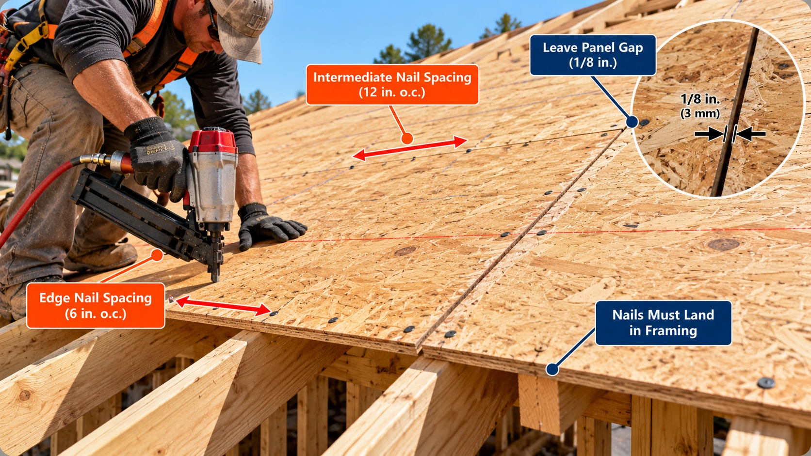
Many references still quote 6 in. at edges and 12 in. at intermediate supports for all sheathing. In Table R602.3(1) of the 2024 IRC, the 8d common and RSRS-01 roof sheathing entries use 6 in. at both edges and intermediate supports. The 6/12 pattern still applies to the wall, subfloor and thicker-panel entries.
Roof panel thickness and span rating are covered in the Roof Sheathing Thickness Chart. This section covers the nails.
Edge and Field Nailing
| Panel thickness | Roof nail alternatives | Edges (in. o.c.) | Intermediate supports (in. o.c.) |
|---|---|---|---|
| 3/8 in. to 1/2 in. | 8d common (2-1/2 × 0.131 × 0.281 head) or RSRS-01 ring-shank (2-3/8 × 0.113 × 0.281 head) | 6 | 6 |
| 19/32 in. to 3/4 in. | 8d common (2-1/2 × 0.131 × 0.281 head) or RSRS-01 ring-shank (2-3/8 × 0.113 × 0.281 head) | 6 | 6 |
| 7/8 in. to 1-1/4 in. | 10d common (3 × 0.148) or 8d deformed (2-1/2 × 0.131 × 0.281 head) | 6 | 12 |
Footnotes also set spacing at 6 in. at all supports where panel spans are 48 in. or greater, and 4 in. on center within 48 in. of roof edges and ridges and at gable end framing where the ultimate design wind speed exceeds 130 mph in Exposure B or 110 mph in Exposure C. The listed spacing applies where roof framing has a specific gravity of 0.42 or larger; for framing from 0.35 up to 0.42 the code calls for RSRS-03 (2-1/2 × 0.131 × 0.281 head) nails.
Ring-Shank Nails
The IRC names RSRS-01 (2-3/8 in. × 0.113 in.) as a ring-shank alternative to the 8d common roof sheathing nail, and RSRS-03 (2-1/2 in. × 0.131 in.) for lower-density framing. Other ring-shank products need to match the table or hold an approval.
Wind Requirements
Higher wind speeds tighten the nail spacing as noted above and may require engineered diaphragm or uplift design.
Perimeter Nailing Intervals for One 4 × 8 ft Panel (illustrative)
Variables: P = panel perimeter (in.); s = nail spacing (in. o.c.); N = number of spacing intervals around the perimeter
Practical interpretation: This is not the nail count per sheet. Actual counts depend on corner counting, which edges are supported, intermediate rows, openings, edge distances and the governing schedule. Estimate only; use the project schedule for ordering.
Wall Sheathing Nail Size and Spacing
Structural Panels
Table R602.3(1) lists 6d common (2 in. × 0.113 in.) nails for 3/8 in. to 1/2 in. panels and 8d common (2-1/2 in. × 0.131 in.) nails for 19/32 in. to 3/4 in. panels at 6 in. on edges and 12 in. at intermediate supports for subfloor and interior wall sheathing. Exterior wood structural panel wall sheathing refers to Table R602.3(3), shown below. Thicker 7/8 in. to 1-1/4 in. panels take 10d common or 8d deformed nails. Plywood thickness categories are in the Plywood Thickness Chart.
Braced Wall Nailing
Braced wall panels follow the bracing methods in R602.10, which have their own nail sizes and spacing. Do not assume the ordinary sheathing row satisfies a braced wall method.
Shear Wall Requirements
Engineered shear walls specify nail size, head, spacing and edge distance in the design. When the panels must resist wind pressure, use Table R602.3(3) below.
| Minimum nail (in.) | Min. penetration (in.) | Panel span rating | Panel thickness (in.) | Max. stud spacing (in.) | Edges / field (in. o.c.) | Max. ultimate wind, Exp. B (mph) | Exp. C (mph) | Exp. D (mph) |
|---|---|---|---|---|---|---|---|---|
| 6d common (2 × 0.113) | 1.5 | 24/0 | 3/8 | 16 | 6 / 12 | 140 | 115 | 110 |
| 8d common (2-1/2 × 0.131) | 1.75 | 24/16 | 7/16 | 16 | 6 / 12 | 170 | 140 | 135 |
| 8d common (2-1/2 × 0.131) | 1.75 | 24/16 | 7/16 | 24 | 6 / 12 | 140 | 115 | 110 |
Where wall framing specific gravity is from 0.35 up to 0.42, the maximum field nail spacing in Table R602.3(3) becomes 8 in.
Subfloor Nail Size and Spacing
Plywood and OSB
Panel subfloor uses the same thickness-based rows as walls, with 6 in. at supported edges and 12 in. at intermediate supports.
| Panel thickness | Nail alternatives | Edges (in. o.c.) | Intermediate (in. o.c.) |
|---|---|---|---|
| 3/8 in. to 1/2 in. | 6d common or deformed (2 × 0.113 × 0.266 head), or 2-3/8 × 0.113 × 0.266 head nail | 6 | 12 |
| 19/32 in. to 3/4 in. | 8d common (2-1/2 × 0.131), or deformed 2-3/8 × 0.113 × 0.266 head | 6 | 12 |
| 7/8 in. to 1-1/4 in. | 10d common (3 × 0.148), or 8d deformed (2-1/2 × 0.131 × 0.281 head) | 6 | 12 |
| Combination subfloor-underlayment, 3/4 in. and less | Deformed (2 × 0.113 or 2 × 0.120), or 8d common (2-1/2 × 0.131) | 6 | 12 |
Fastener Patterns
Edge spacing applies to panel edges supported by framing or blocking and at floor perimeters. Ring or deformed shanks are listed as alternatives in several rows.
Subfloor Adhesives
Construction adhesive is commonly paired with nailing to reduce squeaks. Use the panel manufacturer’s and adhesive manufacturer’s instructions, and still follow the nail schedule.
Face Nailing vs. End Nailing vs. Toe Nailing
The same nail behaves differently depending on how it enters the wood.
Connection Geometry
- Face nailing: driven through the face of one member into another, perpendicular to the grain of both, such as stud to stud.
- End nailing: driven through a member into the end grain of another, such as a plate to a stud end.
- Toe nailing: driven at an angle through the side of one member into another, such as a stud to a plate.
Nail Placement
The schedule gives different quantities for each method. For a stud to a plate, it lists 4-8d common nails when toe-nailed but 2-16d common nails when end-nailed. Follow the row for the method you actually use.
Splitting Prevention
Keep nails away from member ends and edges as the connection allows, stagger rows where permitted, and avoid overdriving.
The simple penetration formula in the next section only fits a perpendicular nail. Toe-nailing cannot be checked with it.
Framing Nail Penetration Depth
Penetration Formula
For a nail driven straight through one member into another, the nominal penetration is the nail length minus the thickness of the attached member. Actual lumber is thinner than its nominal name, so use real thickness; see the Lumber Size Chart for actual dimensions (a nominal 2× is 1-1/2 in. thick).
3-Inch vs. 3-1/2-Inch Nails
| Nail length (in.) | Nominal penetration (in.) |
|---|---|
| 2 | 0.50 |
| 2-1/2 | 1.00 |
| 3 | 1.50 |
| 3-1/4 | 1.75 |
| 3-1/2 | 2.00 |
| 4 | 2.50 |
Worked Examples
Nail Penetration Through 2× Lumber
Variables: p = nominal penetration into the receiving member (in.); L = nail length (in.); t = thickness of the attached member (in.)
Practical interpretation: This assumes a perpendicular nail with the head seated flush. It is an illustrative geometric value, not a statement that the connection is adequate.
Penetration With a 3-Inch Framing Nail
Variables: Same variables as Example 1
Practical interpretation: The 3 in. nail gives 1/2 in. less nominal penetration than the 16d common. That does not by itself show which nail the connection allows.
Design Penetration Is Different
For engineered connections, the NDS sets penetration-based design values and reductions. The code schedule, not this simple subtraction, governs the actual nail length. Toe-nailed and angled nails need separate consideration.
Framing Nail Spacing and Edge Distance
On-Center Spacing
On-center (o.c.) spacing is measured center to center between nails in a row. The tables give it for each row, for instance 24 in. for 16d common stud-to-stud nailing and 12 in. for a double top plate with 10d box nails.
End and Edge Distances
Nails placed too close to a member’s end or edge can split the wood. The IRC schedule does not list a universal distance for every row. Engineered connections follow NDS end distance, edge distance and spacing rules. For particleboard wall sheathing, the code notes nails must be at least 3/8 in. from panel edges.
Staggered Nail Patterns
Where two or more rows are required, such as the top and bottom of a built-up girder, the rows are staggered so nails do not line up along one grain line. Spacing for ordinary framing, sheathing and engineered connections is not interchangeable.
Framing Nail Strength and Load Capacity
Nail strength is not a function of penny size alone, so this page does not publish a single load value for an 8d, 10d or 16d nail.
Lateral Resistance
Under the NDS, lateral capacity depends on nail diameter, bending yield strength, wood species and specific gravity, member thickness, penetration, load direction, spacing, end and edge distance, and adjustment factors such as load duration and moisture.
Withdrawal Resistance
Withdrawal resistance depends on diameter, penetration, species and specific gravity, shank type and moisture condition.
NDS Design Requirements
Use NDS Chapter 12 and the project’s design conditions. Do not mix provisions or design values from different NDS editions. The shank area comparison earlier on this page shows size only; it is not a capacity ratio.
Framing Nails for Pressure-Treated and Exterior Lumber
Preservative chemicals corrode some metals quickly. The 2024 IRC (Section R304.3, formerly R317.3.1) requires fasteners in contact with preservative-treated wood to be hot-dipped zinc-coated galvanized steel, stainless steel, silicon bronze or copper.
| Nail finish | Typical exposure | Code and installation note |
|---|---|---|
| Bright (plain) steel | Interior, dry framing | Not suitable for preservative-treated wood or wet exterior use |
| Hot-dip galvanized | Preservative-treated and exterior wood | Named in the code for treated wood; check the coating standard |
| Stainless steel | Treated wood and severe exposure | Named in the code; the IRC nail schedule requires engineering or approval for stainless framing nails |
| Silicon bronze or copper | Treated wood where specified | Also named in the code for treated wood |
Galvanized Nails
Hot-dip galvanized nails carry a thick zinc coat and are the usual choice for treated framing and exterior work. Electroplated or bright nails do not carry the same protection.
Stainless Steel Nails
Stainless nails give the best corrosion resistance, but their structural use in framing must be engineered or approved as noted under Table R602.3(1).
Corrosion Compatibility
Match the nail, the metal connector and the lumber treatment. Follow the treated-lumber supplier’s fastener recommendations.
Framing Nails for Metal Connectors
Metal connectors are tested with specific nails. A 16d hardware nail from Simpson Strong-Tie is 2-1/2 in. × 0.162 in., a full inch shorter than a 16d common nail, because a long nail can poke through a joist or hanger flange.
| Penny label | Simpson Strong-Tie hardware nail | Common framing nail |
|---|---|---|
| 8d | 1-1/2 × 0.131 | 2-1/2 × 0.131 |
| 10d | 1-1/2 × 0.148 | 3 × 0.148 |
| 16d | 2-1/2 × 0.162 | 3-1/2 × 0.162 |
Joist Hangers
Fill every hanger hole with the nail type the manufacturer lists, in the quantity shown in its table.
Hurricane Ties and Straps
Ties, straps and hold-downs carry load calculated for a defined fastener. Different nail dimensions change the published capacity.
Manufacturer-Specified Nails
No Substitutions Without Approval
Use the connector manufacturer’s published fastening schedule. A standard framing nail may be too long, too thin, have the wrong head or fail to meet the listed requirement.
How to Choose the Correct Framing Nail Size
Connection and Code
- Identify the exact connection.
- Check the adopted code and approved plans.
Nail Dimensions
- Determine the specified nail length.
- Verify the shank diameter.
- Verify the nail type and head.
- Confirm the required quantity and spacing.
- Check penetration against the wood thickness.
Installation and Material
- Verify the material and coating for the exposure.
- Check the nailer’s compatibility, if using a tool.
- Inspect the installed nails for quality.
Common Framing Nail Mistakes
Size and Diameter Errors
Choosing by penny size alone
Penny size does not set diameter, head or type.
Treating 16d sinkers as 16d commons
A 16d sinker is 1/4 in. shorter and thinner.
Assuming every 3 in. nail is a 10d common
3 × 0.131 is not 3 × 0.148.
Using thinner nails without an approved alternative
Use only the diameters the row lists.
Ignoring shank diameter
Diameter drives lateral and withdrawal resistance.
Nail-Gun Errors
Using the wrong collation
Wire, plastic and paper strips do not interchange.
Using incompatible head styles
Match the tool manual and the approved nail.
Overdriving nails
Crushed wood cuts bearing and holding.
Underdriving nails
Proud heads leave the connection loose.
Missing the framing member
A nail through sheathing alone holds nothing.
Structural Fastening Errors
Using insufficient penetration
The nail must reach well into the receiving member.
Splitting lumber near edges
Reposition or stagger nails before they split the wood.
Ignoring braced wall nailing
Bracing methods have their own nailing rules.
Using ordinary nails in metal connectors
Use the manufacturer’s specified nails.
Using bright nails in treated or wet exposure
Use hot-dip galvanized or stainless nails.
Assuming 6/12 spacing fits every sheathing
Roof entries differ, and wind changes spacing.
Ignoring wind and seismic requirements
High-load areas need engineered fastening.
Framing Nail Chart Limitations and Safety
Reference vs. Structural Design
This chart does not determine structural connection capacity, complete framing compliance, the required fastener count for every connection, shear wall resistance, wind-uplift capacity, seismic resistance, suitable connector nails, corrosion performance or nail-gun safety.
The Adopted Code and Approved Plans Control
Table rows shown here are selected examples from the 2024 IRC. Check the adopted code edition, local amendments, the approved plans, the engineer’s design and the manufacturer’s instructions. Always wear eye and hearing protection and follow the tool manual when using a nail gun.
Code and Inspection Requirements
Inspectors check the nail size, type, number and spacing against the plans and the adopted code. Keep nail boxes or product data on site when a nail is not the standard common nail.
Primary References
- 2024 International Residential Code, Chapter 6, Wall Construction (ICC)
- ASTM F1667/F1667M, Driven Fasteners: Nails, Spikes, and Staples
- American Wood Council, National Design Specification (NDS) for Wood Construction
- Simpson Strong-Tie, Fastener Overview: Nails
- APA, The Engineered Wood Association
For related fasteners, the Wood Screw Size Chart covers screws, which are sometimes specified in place of nails for ledgers, subfloors and connectors.
Framing Nail Size FAQs
Nail Sizes and Types
What size nails are used for framing?
Most residential framing uses 8d, 10d and 16d common nails, or nail-gun nails with matching dimensions. The exact nail comes from the fastening schedule for each connection, so check the code row and the approved plans.
What size nails should I use for 2×4 framing?
Nail size depends on the connection, not the stud width. In the 2024 IRC schedule, a stud is end-nailed to a plate with two 16d common nails (3-1/2 × 0.162 in.) or toe-nailed with four 8d common nails (2-1/2 × 0.131 in.), and studs are face-nailed to each other with 16d common nails at 24 in. on center where not at braced wall panels. A 2×6 wall uses the same rows.
What is the difference between 8d, 10d and 16d nails?
The common versions are 2-1/2 × 0.131 in. (8d), 3 × 0.148 in. (10d) and 3-1/2 × 0.162 in. (16d). Box and sinker versions of the same penny size are thinner, and sinkers can also be shorter.
How long is a 16d framing nail?
A 16d common nail is 3-1/2 in. (88.9 mm) long, and a 16d box nail is the same length. A 16d sinker nail is 3-1/4 in. long.
Is a 3-1/4-inch nail a 16d nail?
It matches the length of a 16d sinker (3-1/4 × 0.148 in.), not a 16d common nail (3-1/2 × 0.162 in.). Do not treat it as a 16d common nail unless the code or an approval allows it.
Is a 3-inch framing nail the same as a 10d common?
No. A 10d common nail is 3 in. × 0.148 in., while many gun nails are 3 in. × 0.131 in. The IRC names 3 × 0.131 in. nails in specific rows, but that does not make them equal to a 10d common nail.
What size framing nails should I use for wall studs?
Use the row for the exact connection: end-nailed or toe-nailed to plates, face-nailed to other studs, and tighter spacing at braced wall panels. The wall stud section above shows selected 2024 IRC entries.
What size nails are used for double top plates?
The 2024 IRC lists face nailing of one top plate to the other with 16d common nails at 16 in. on center, or 10d box or 3 × 0.131 in. nails at 12 in. on center. Plate end joints take a larger group of nails and must be offset at least 24 in.
What nails are used for headers?
A built-up header of two 2-inch members with a 1/2 in. spacer uses 16d common nails at 16 in. on center along each edge, or 16d box nails at 12 in. on center. Engineered headers follow the manufacturer’s schedule.
What size nails are used for rafters?
Rafters and roof trusses are toe-nailed to the plate with three 10d common nails (two on one side, one on the other), or the listed alternatives. Wind uplift may require metal connectors instead.
What nails are used for roof sheathing?
For 3/8 in. to 3/4 in. panels, the 2024 IRC lists 8d common (2-1/2 × 0.131 in.) or the RSRS-01 ring-shank nail (2-3/8 × 0.113 in.) at 6 in. on edges and 6 in. on intermediate supports. Thicker panels, high wind and low-density framing change the requirement.
What nails are used for subflooring?
Panels 3/8 in. to 1/2 in. thick list 6d common or deformed nails, and 19/32 in. to 3/4 in. panels list 8d common or deformed nails, at 6 in. on edges and 12 in. on intermediate supports. Check the panel manufacturer’s instructions as well.
Are ring-shank nails better for framing?
Ring-shank nails resist pull-out better than smooth nails, which is why roof and subfloor sheathing allow them. They are not a universal substitute for common nails, because diameter, length, head and the fastening schedule still apply.
Are pneumatic nails code-approved?
Not automatically. The IRC recognizes some dimensionally specified nails, such as 3 × 0.131 in. in certain rows. Any other gun nail must match the listed nail or carry an approval for that use.
Can clipped-head nails be used for framing?
Sometimes. Some clipped-head nails have evaluation reports for use under the IRC, but some jurisdictions and engineered plans restrict them. Check the adopted code, the product evaluation and the plans.
What is the difference between 21° and 30° framing nails?
The numbers describe the magazine angle and, generally, the strip type: 21° tools use plastic-collated strips and 30° tools use paper-collated strips. The angle is not a strength rating.
Can I use framing nails in joist hangers?
Not unless the hanger manufacturer lists them. Connectors use specified nails, which can be shorter than standard framing nails, and the load tables assume that nail.
How deep should framing nails penetrate?
There is no single minimum for every connection. For a perpendicular nail, penetration is the nail length minus the attached member’s thickness. The code schedule and, for engineered work, the NDS decide what is adequate.
What nails are suitable for pressure-treated lumber?
The code names hot-dipped zinc-coated galvanized steel, stainless steel, silicon bronze or copper for fasteners in contact with preservative-treated wood. Follow the lumber treatment supplier’s recommendations too.
How many nails are needed per 4×8 sheathing panel?
There is no single number. A 4 × 8 ft panel has a 288 in. perimeter, which is 48 intervals at 6 in. spacing, but the actual count depends on supported edges, intermediate framing rows, corner counting, openings and the governing schedule.
Download Framing Nail Size Chart PDF
Use your browser’s print function to save this page as a PDF for jobsite binders and estimating folders. The printed version hides interactive elements and keeps the tables.