Anchor Bolt Spacing Chart – Foundation & Sill Plate Rules
Anchor Bolt Spacing Chart
Foundation & Sill Plate Rules
Anchor bolt spacing, minimum diameter, embedment, end distances, and sill plate layouts under the 2024 IRC, with practical bolt-count examples.
 Reviewed by Muhammad Ramzan Babar, PhD Researcher (Plasma Physics) & Calculator Developer, View Profile
The familiar 6-foot rule is only a starting point
A compliant anchor bolt layout must satisfy spacing, end distance, quantity, embedment, positioning, and applicable wind/seismic requirements together, not merely place bolts every six feet. This page uses the model 2024 IRC as its baseline; always verify the locally adopted code edition and any amendments before finalizing a layout.
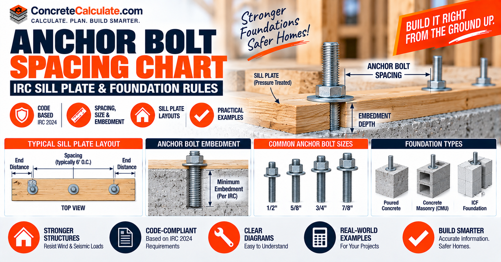
2024 IRC Foundation Anchor Bolt Quick Reference
Based on the model 2024 IRC R403.1.6 and R403.1.6.1. Special short-wall exceptions, seismic requirements, approved alternative anchors, and local amendments can alter the applicable details.
| Requirement | Value |
|---|---|
| Minimum bolt diameter | 1/2 in |
| Maximum spacing on center | 6 ft |
| Minimum embedment | 7 in into concrete or grouted masonry cells |
| End distance | Not more than 12 in, not less than 7 bolt diameters, from each plate-section end |
| Minimum quantity | 2 bolts per plate section |
| Position across plate width | Middle third of the plate |
| Nut and washer | Required; larger plate washer required in specified seismic braced wall applications |
Seven-Bolt-Diameter Minimum End Distance
| Bolt Diameter | Seven Bolt Diameters |
|---|---|
| 1/2 in | 3-1/2 in |
| 5/8 in | 4-3/8 in |
| 3/4 in | 5-1/4 in |
These are arithmetic equivalents of the IRC’s seven-diameter rule, not separate universal minimum distances for all concrete anchors.
Important Distinction
Maximum spacing between bolts, distance from a plate end, and minimum spacing between adjacent anchors are three different measurements. The IRC’s general 6-ft rule is not an ACI minimum-spacing rule for concrete breakout or a universal spacing requirement for equipment anchor groups.
What Is Anchor Bolt Spacing?
The distance between adjacent foundation anchor bolts.
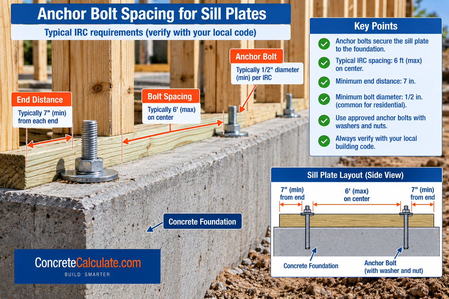
Anchor bolt spacing is the distance between adjacent foundation anchor bolts, measured center to center. This chart focuses on ordinary sill-plate anchorage, which is distinct from column base plates, hold-down anchors, mechanical anchors, and adhesive anchors, each of which follows its own spacing rules covered in later sections.
Center-to-Center Spacing vs Clear Spacing
Two related but distinct dimensional measurements.
Definitions
Center-to-center spacing (s): distance between bolt centerlines. Clear distance between bolt shafts: s(clear) = s – d, where d is bolt diameter.
Prescriptive sill-plate layout normally uses on-center spacing, whereas engineered anchor design also checks clearances, edge distances, and group effects that go beyond the simple on-center measurement.
2024 IRC Foundation Anchorage Requirements
The core authority section for this entire chart.
Section R403.1.6 covers which sill plates and sole plates require anchorage, minimum diameter, maximum spacing, required nuts and washers, bolt positioning, and accepted alternatives. Wood sill plates and wood wall sole plates resting on continuous concrete or masonry foundations, and wood sole plates of braced wall panels at building interiors on monolithic slabs, are subject to these anchorage requirements. The local jurisdiction determines which code edition applies.
✓ Verified Against 2024 IRC Section R403.1.6The 6-Foot Anchor Bolt Spacing Rule
The general prescriptive maximum, explained carefully.
The general maximum is 6 ft on center for applicable prescriptive foundation anchorage. Measure successive centerlines along the plate to verify compliance. An uninterrupted long sill plate still requires bolts near both ends, since the end-distance requirement applies independently of the maximum on-center spacing rule.
4-Foot vs 6-Foot Anchor Bolt Spacing
When the tighter spacing applies.
Ordinary prescriptive anchorage uses the 6-ft maximum. The IRC requires a 4-ft maximum for buildings over two stories in specified seismic design category provisions. Closer spacing can also be specified by engineered wind or seismic design for other conditions, but 4 ft should not be presented as a universal high-wind or seismic requirement; the specific applicable provision must be identified for the project.
✓ Verified Against 2024 IRC Section R403.1.6.1Anchor Bolt End Distance Chart
One of the most valuable additional tables on this page.
| Requirement | Value |
|---|---|
| Maximum distance from plate-section end | 12 in |
| Minimum distance from plate-section end | 7 bolt diameters |
| 1/2-in bolt minimum | 3-1/2 in |
| 5/8-in bolt minimum | 4-3/8 in |
| 3/4-in bolt minimum | 5-1/4 in |
Distance along the wood sill plate is a separate measurement from distance to the edge of the concrete or masonry itself; see the concrete edge distance section later on this page.
Minimum Number of Anchor Bolts per Sill Plate
Why short sections do not qualify for a single bolt.
The ordinary minimum is two bolts per plate section, including for short offset sections subject to the express exceptions permitted in R403.1.6. A 4-ft plate section does not automatically qualify for a single bolt just because it is shorter than the maximum 6-ft spacing; the two-bolt minimum applies regardless of section length.
Anchor Bolt Layout for Common Sill-Plate Lengths
A practical illustrative example chart, not a substitute for the full code requirements.
| Plate Length | Bolt Count at 6-ft Max | Bolt Count at 4-ft Max |
|---|---|---|
| 4 ft | 2 | 2 |
| 6 ft | 2 | 2 |
| 8 ft | 2 | 3 |
| 10 ft | 3 | 3 |
| 12 ft | 3 | 4 |
| 16 ft | 4 | 5 |
| 20 ft | 4 | 6 |
Assumes ordinary straight sill-plate sections, one bolt positioned 12 in from each end, at least two bolts per section, and no special engineered anchorage. These are illustrative layouts, not a substitute for the code’s full requirements. The 4-ft column is particularly useful when a project requires that closer spacing, but the correct requirement must be established first. The layout also needs to be reconsidered wherever a continuous wall is divided into separate plate sections.
How to Calculate the Number of Anchor Bolts
A repeatable layout method.
Bolt Count Workflow
Anchor Bolt Spacing at Sill-Plate Joints
Why separate plate sections each need their own end anchorage.
Butt joints, corners, openings, and short sections each create a separate plate section requiring its own minimum two bolts and compliant end distances. Two abutting sill plates each need their own end bolt near the joint; the joint does not count as a single continuous run for spacing purposes.
Anchor Bolt Position Across the Sill Plate
The IRC’s middle-third requirement.
Anchor bolts must be located in the middle third of the plate width. A standard 2×4 sill plate (actual width 3-1/2 in) has a much narrower middle-third zone than a 2×6 sill plate (actual width 5-1/2 in). See the Lumber Size Chart for the actual dimensions behind these nominal plate sizes.
✓ Verified Against 2024 IRC Section R403.1.6Anchor Bolt Embedment Depth
The IRC’s minimum embedment for prescriptive sill-plate anchorage.
The minimum embedment is 7 in into concrete or grouted CMU cells for applicable prescriptive sill-plate anchorage. This is distinct from total bolt length, and also distinct from the effective embedment used in engineered anchor calculations, which can account for additional factors beyond this simple prescriptive minimum.
✓ Verified Against 2024 IRC Section R403.1.6Anchor Bolt Length vs Embedment Depth
The components that make up total bolt length.
Total anchor bolt length includes embedment, the concrete-to-sill projection, sill-plate thickness, washer, nut, and sufficient thread engagement beyond the nut. See the Anchor Bolt Size Chart for complete bolt-length and dimension information across common diameters.
Anchor Bolt Washers and Nuts
Ordinary requirements and the separate seismic plate washer provision.
A nut and washer are required for ordinary sill plate anchorage. Under the 2024 IRC, Section R602.11.1 requires larger plate washers measuring at least 0.229 in by 3 in by 3 in for specified seismic braced wall panel anchorage, subject to its stated details and exceptions. Do not assume every installation needs the larger seismic plate washer; verify which condition applies to the specific wall.
✓ Verified Against 2024 IRC Section R602.11.1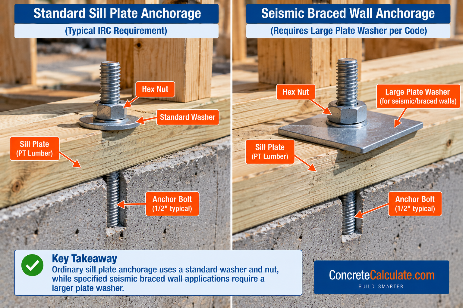
Cast-in-Place Anchor Bolts vs Post-Installed Anchors
Two fundamentally different installation approaches.
Cast-in-place J-bolt, L-bolt, and headed anchor bolts are set into wet concrete before it cures. Mechanical and adhesive post-installed anchors are drilled and set into cured concrete afterward. Post-installed fasteners have product-specific minimum spacing, edge distance, embedment, drilling, cleaning, and installation requirements established through product evaluation testing, distinct from the IRC’s cast-in-place sill-plate rule.
Concrete Edge Distance vs Bolt End Distance
A frequently confused but critical distinction.
Bolt end distance measures from the anchor bolt to the end of the wood sill plate section. Concrete edge distance measures from the anchor to the edge of the concrete or masonry itself. An IRC-compliant location along the wood plate does not automatically establish adequate concrete breakout capacity; these are two entirely separate measurements that both matter for a fully compliant installation.
Concrete Foundation Walls vs Grouted CMU Foundations
Why the foundation material changes installation details.
Anchor placement into cast concrete follows different installation considerations than placement into grouted masonry cells. A hollow, ungrouted cell cannot be assumed to provide the same anchorage as solid concrete or a properly grouted cell; the prescriptive embedment requirement specifically assumes grouted cells, not hollow masonry construction.
Anchor Bolt Spacing for Braced Wall Panels
How anchorage connects the lateral-load path to the foundation.
Anchorage connects braced wall lines to the foundation as part of the overall lateral-load path. Prescriptive anchor-bolt spacing generally applies, but panel configuration, uplift demand, bracing method, and other connection details can lead to special anchorage requirements beyond the ordinary sill-plate rule.
Anchor Bolt Spacing in Seismic Design Categories
Comparing categories without creating one universal spacing-by-zone table.
The 2024 IRC includes specific requirements for light-frame structures in Seismic Design Categories D0, D1, and D2, and for qualifying townhouses in Category C. These include the 4-ft spacing condition for buildings over two stories, interior plate anchorage requirements, large plate washers, and implications for stepped cripple walls. Do not turn this into one universal spacing-by-seismic-zone table; the specific seismic design category and building configuration together determine the applicable requirement.
✓ Verified Against 2024 IRC Section R403.1.6.1Anchor Bolt Spacing in High-Wind Areas
Why wind cannot be reduced to a single nationwide chart.
Wind design involves the complete roof-to-foundation load path, uplift, lateral shear, local exposure, and engineered requirements specific to the site. Wind demands may lead to closer spacing, hold-downs, or alternative anchors, but this cannot be reduced to a single nationwide wind-speed spacing chart; the specific design wind speed, exposure category, and building configuration all factor into the actual requirement.
Anchor Straps and Alternative Foundation Anchorage
Approved alternatives to ordinary bolts.
Approved anchor straps or other anchorage systems may replace ordinary bolts where equivalent performance is documented. Manufacturer guides publish specific approved installations and replacement-spacing tables, not universal one-for-one substitutions for bolts; the specific product’s evaluation and installation instructions govern its approved use.
Hold-Down Anchors vs Ordinary Sill-Plate Bolts
Distributed anchorage versus concentrated connections.
Ordinary sill-plate bolts provide distributed anchorage along the length of the wall. Hold-down anchors provide concentrated overturning and uplift connections at shear-wall ends. Hold-down anchor diameter, quantity, location, and reinforcement require system-specific structural design rather than the general sill-plate spacing rule covered throughout the rest of this chart.
ACI 318-25 Anchor Spacing and Edge Distance
The principal engineered-anchorage section.
ACI 318-25 Chapter 17 governs anchoring to concrete, including tension, shear, interaction, spacing, edge distance, concrete member thickness, and earthquake-resistant anchor design. Section 17.9 (numbered 17.7 in some prior editions) addresses spacing, edge-distance, and thickness requirements to preclude splitting. In the absence of product-specific test information, the code identifies minimum edge distances that vary by anchor type, for example roughly 6 times the anchor diameter for adhesive and undercut anchors and roughly 8 times the anchor diameter for torque-controlled expansion anchors, with critical edge distance requirements expressed as a multiple of effective embedment depth.
✓ Verified Against ACI 318-25 Chapter 17Minimum Anchor Spacing by Anchor Type
Why one universal table cannot serve every anchor product.
Cast-in anchors, expansion anchors, screw anchors, and adhesive anchors cannot share one universal minimum-spacing table, since their capacity and required spacing depend on the specific product’s evaluated test data. For detailed numerical examples, refer to a specific manufacturer’s evaluated anchor product, diameter, embedment, and base-material condition rather than a generic cross-product table.
How Spacing and Edge Distance Affect Anchor Capacity
The engineering concept without reproducing a full design manual.
Overlapping concrete breakout regions, splitting, group action, and edge proximity all reduce an anchor’s effective capacity when anchors are placed too close together or too near a concrete edge. Manufacturer product data commonly show that a given anchor’s allowable spacing depends on edge distance and product configuration, meaning the same anchor diameter can have different allowable spacing depending on where it is installed relative to the concrete edge.
Anchor Bolt Spacing for Column Base Plates
Kept concise, since this page’s primary focus is residential foundation anchorage.
Steel column base plates involve bolt patterns dictated by the base plate’s hole positions, concrete pier or footing edges, and applied moment and shear. This is an engineered layout question, not a residential prescriptive one; see the Base Plate Calculator for base-plate-specific sizing.
Anchor Bolt Spacing for Equipment and Post Bases
A warning against misapplying the residential rule.
Equipment and post base anchorage depends on manufacturer base-plate patterns, equipment loads, vibration, edge distances, and anchor group effects. Do not transfer the residential 6-ft spacing rule to these applications; each equipment or post base product has its own specified anchor pattern and spacing requirements.
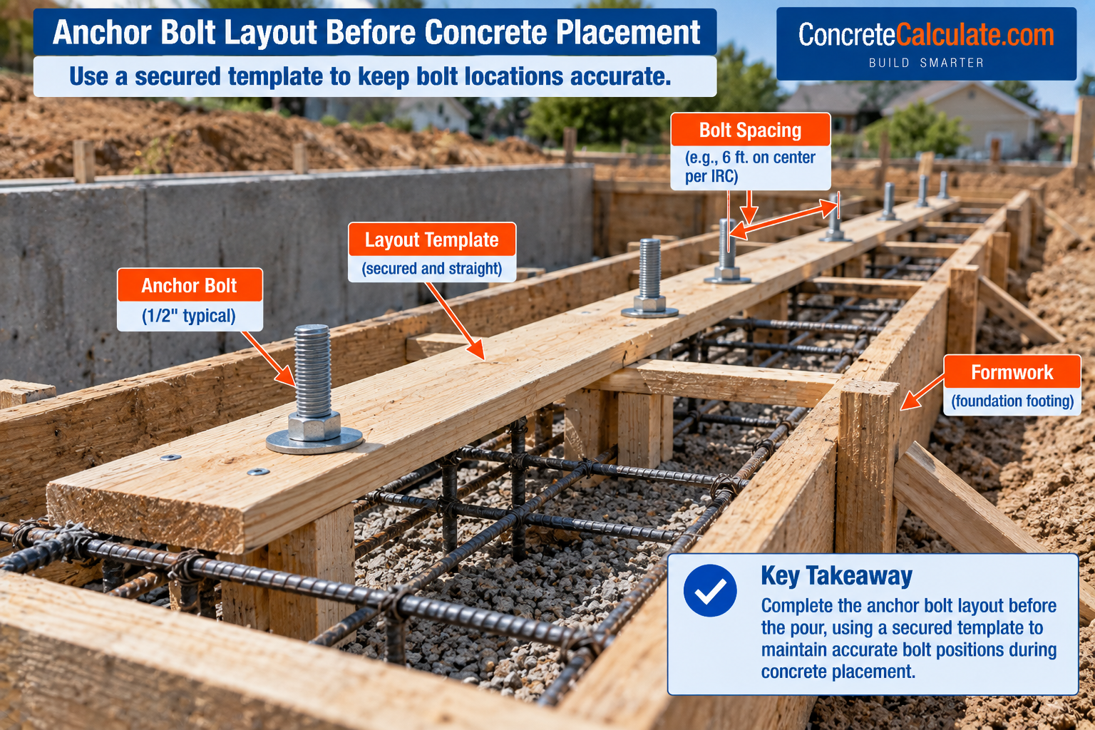
How to Lay Out Anchor Bolts Before Pouring Concrete
A practical construction workflow.
Pre-Pour Layout Workflow
Anchor Bolt Spacing Inspection Checklist
A printable field checklist.
| Item | Check |
|---|---|
| Diameter | Minimum 1/2 in or as specified |
| Spacing | Maximum 6 ft on center, or 4 ft where required |
| Plate end distance | 12 in max, 7 diameters min, from each end |
| Bolt count | Minimum 2 per plate section |
| Embedment | Minimum 7 in into concrete or grouted cells |
| Bolt position | Middle third of plate width |
| Washer/nut | Standard or large seismic plate washer as applicable |
| Foundation type | Solid concrete or properly grouted masonry cell |
| Approved plan details | Match installed condition to approved plans |
| Special notes | Seismic or wind provisions applied where required |
How to Check Existing Anchor Bolt Spacing
A field verification method for existing construction.
Measure center-to-center spacing along each plate section. Check each separate plate section individually rather than the wall as a whole. Inspect washer and nut engagement for proper tightening. Identify any missing anchors near plate ends or joints. Review the locally adopted code or an approved retrofit detail for the specific project rather than assuming an unsupported universal retrofit approach applies.
Common Anchor Bolt Spacing Mistakes
Using 6 ft for every condition
Seismic and wind provisions can require closer spacing than the ordinary maximum.
Omitting end bolts
The end-distance requirement applies independently of the maximum on-center spacing.
Overlooking separate plate sections
Each joint, corner, or opening creates its own plate section requiring compliant anchorage.
Confusing plate-end and concrete-edge distances
These are two separate measurements that both matter for a compliant installation.
Providing inadequate embedment
The 7-in minimum applies to ordinary prescriptive anchorage; some conditions require more.
Misaligning bolts outside the middle third
Bolts placed too close to either edge of the plate do not satisfy the positioning rule.
Using incorrect washers
Seismic braced wall applications require a larger plate washer than the standard washer.
Assuming ungrouted masonry cells provide adequate anchorage
Prescriptive embedment assumes grouted cells, not hollow masonry construction.
Using improper anchor substitutions
Alternative anchors and straps require documented equivalent performance, not assumption.
Using residential rules for engineered base plates
Column base plates and equipment anchors require engineered, product-specific layouts.
Anchor Bolt Spacing Chart Limitations
Read Before Foundation Anchorage Design or Installation
Model-code prescriptive guidance applies only to qualifying buildings and details. It does not replace project-specific foundation design, post-installed anchor evaluation reports, engineered wind or seismic design, or local code amendments. Column base plates, equipment anchors, and hold-down connections require product-specific or engineered layouts rather than this general sill-plate reference. Always verify the locally adopted code edition, any amendments, and the applicable seismic design category or wind design criteria for the specific project before finalizing an anchor bolt layout.
Frequently Asked Questions
Download Anchor Bolt Spacing Chart PDF
Save or print this reference including the IRC quick-reference table, end-distance and bolt-count charts, embedment and washer requirements, and the pre-pour layout and inspection workflows.