Wood Beam Span Chart – size, Load, Species & Grade Guide
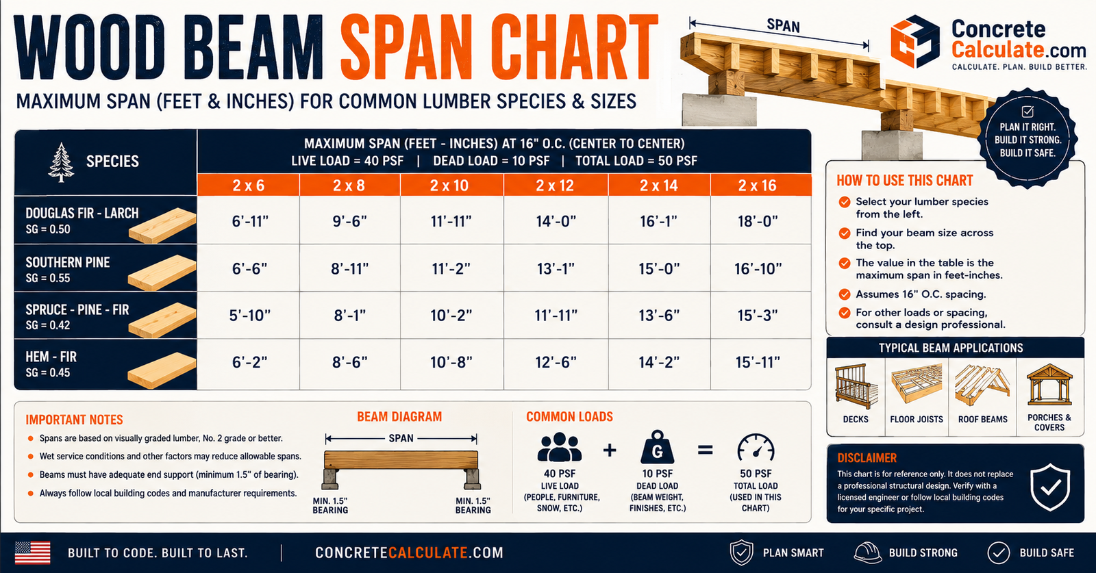
Wood Beam Span Chart
Size, Load, Species & Grade Guide
Use this chart to understand the inputs behind wood-beam selection. A valid span depends on actual loading, species, grade, member size, stiffness, shear, bearing and support conditions.
 Reviewed by Muhammad Ramzan Babar, PhD Researcher & Calculator Developer · View Profile
A statement such as “a 2×10 spans 15 feet” is incomplete and potentially unsafe without load, tributary width, species, grade, support, deflection and other assumptions. Use the Wood Beam Span Calculator or obtain a qualified structural design for an actual project.
⭐ Wood Beam Span Chart: Quick Answer
A wood beam span chart links a known span and load to a trial lumber size, species and grade. It then requires verification of bending, stiffness, shear, bearing and applicable adjustment factors.
| Wood Beam Size | Span | Load | Species | Grade | Allowable Load |
|---|---|---|---|---|---|
| Any solid-sawn size | Clear support-to-support span | Uniform load and any point loads | Specified commercial species group | Marked lumber grade | Calculated or table value for stated assumptions |
| 2×6 through 2×16 | Not a standalone input | Floor, roof, deck or other stated load | Example: S. Pine, D.Fir-L, Hem-Fir, SPF | Select Structural, No.1, No.2 or No.3 | Verify Fb, E, Fv, bearing and deflection |
| 4×6 through 6×12 | Not a standalone input | Actual tributary area and reactions | Use identified species values | Use identified grade values | Check member and supports together |
AWC’s beam-load-table procedure starts with known span and load, selects a trial species, size and grade, then checks bending capacity, stiffness and shear. Bearing and other applicable conditions must also be verified.
⭐ Master Wood Beam Span Chart
This is a selection matrix for common residential beam sizes, not a list of universal maximum spans. AWC beam-load tables cover spans from 4 to 32 feet and member sizes from 2×4 to 24×24 inches.
| Common Size | Typical Role | Design Inputs Required | Selection Check |
|---|---|---|---|
| 2×6 | Light beams, headers or short-span framing where designed | Span, load, species, grade, support | Bending, E, shear, bearing |
| 2×8 | Light to moderate designed beam applications | Tributary width, distributed and point loads | Strength and deflection |
| 2×10 | Common deeper lumber trial size | Application, support and lateral restraint | Fb, E, Fv and bearing |
| 2×12 | Higher-depth solid lumber option | Load path and deflection criterion | Strength, stiffness and stability |
| 2×14 / 2×16 | Availability-dependent deep solid lumber | Actual dressed dimensions and grade | Consider handling and engineered alternatives |
| 4×6 / 4×8 | Timber, porch or deck-related applications where designed | Orientation, outdoor exposure, post reactions | Strong-axis installation and bearing |
| 4×10 / 4×12 | Heavier solid-sawn beam candidates | Species, grade, load duration and moisture | All member and connection checks |
| 6×6 / 6×8 | Posts or beams depending on orientation and load | Actual structural role and load combination | Do not confuse post capacity with beam capacity |
| 6×10 / 6×12+ | Large solid-sawn applications where available | Full design and procurement verification | Consider glulam, LVL or steel alternatives |
⭐ Wood Beam Span by Beam Size
Every listed size has a different allowable span under a different load and species/grade combination. Use the sections below as long-tail selection guidance, not as preapproved spans.
| Beam Size | What Controls Its Span | Most Useful Next Step |
|---|---|---|
| 2×6 | Limited depth makes bending and deflection important quickly | Define load and check a table or calculator |
| 2×8 | Species, grade and tributary width can change suitability substantially | Verify Fb and E requirements |
| 2×10 | Often a trial size for moderate spans, never a universal answer | Check bending, shear and deflection |
| 2×12 | Greater depth improves moment and stiffness performance | Confirm bearing and lateral support too |
| 2×14 / 2×16 | Availability, actual dimensions and handling become relevant | Compare solid lumber with engineered wood |
| 4×6 / 4×8 | Orientation is critical for rectangular timbers | Install with depth vertical unless designed otherwise |
| 4×10 / 4×12 | Heavier member but still controlled by loading and support | Check posts, footings and connections |
| 6×6 / 6×8 / 6×10 / 6×12 | May function as a post or beam based on orientation | Use the correct beam, column or deck-design procedure |
Wood Beam Span by Span Length
AWC generic beam-load tables use a broad 4 to 32 foot range. The practical question at every length is what load and deflection requirement the beam must satisfy.
| Clear Span | Planning Focus | Typical Design Direction |
|---|---|---|
| 6 ft | Short span, but point loads and bearing can still control | Establish actual reactions |
| 8 ft | Common opening and deck-module length | Check load path and species/grade |
| 10 ft | Common remodeling opening length | Do not size by span alone |
| 12 ft | Deflection becomes increasingly influential for floor loads | Compare depth and stiffness options |
| 14–16 ft | Long residential opening range | Deeper solid lumber, built-up or engineered beam may be evaluated |
| 18–20 ft | Long-span loading and support reactions increase | Professional or engineered selection is often appropriate |
| 24–28 ft | Large opening or special application | Engineered wood or steel comparison often becomes useful |
| 30–32 ft | Upper generic-table range cited by AWC WSDD | Full project-specific design required |
⭐ Wood Beam Span by Load
The same beam can have very different allowable spans under light roof loading, a residential floor, a deck or a significant point reaction.
| Load Category | Typical Source | Beam Design Issue |
|---|---|---|
| Light uniform load | Limited ceiling or light roof component | Still verify loading and deflection |
| Moderate uniform load | Typical framed floor or roof area | Tributary width converts area load to line load |
| Heavy uniform load | Storage, heavy roof assembly or broad structural load | Bending, shear and support reactions rise |
| Floor load | Occupants, furniture, flooring, joists and ceiling | Strength plus serviceability are important |
| Roof load | Roof dead load, snow and rafters or trusses | Snow and point reactions may govern |
| Deck load | Decking, joists, occupants and railing system | Exterior exposure, posts and footings matter |
| Point load | Post above, truss reaction, wall reaction or beam reaction | Do not apply a generic uniform-load table without analysis |
Total load vs uniform load
Total load is measured in pounds. Uniform line load is pounds per linear foot, abbreviated plf. A total 10,000 lb load is not automatically 10,000 lb/ft. Its location and distribution along the beam affect moment, shear and deflection.
Area load to line load
Floor and roof loads are commonly specified in pounds per square foot. Multiply the applicable area load by tributary width in feet to obtain an approximate uniform line load in plf, after establishing the actual framing geometry.
Wood Beam Span for Floor, Roof, Deck & Remodeling Applications
Application changes the load path and design inputs.
Floor beams and basement beams
Floor joists deliver tributary floor load to the beam, then beam reactions travel through posts to foundations. Open-plan floors, crawlspaces and basement beams require post and footing checks in addition to beam selection.
Roof beams and trusses
Rafters or trusses can deliver roof dead load, roof live load and snow load. Truss bearings may introduce concentrated reactions that differ from a uniform roof load.
Deck beams
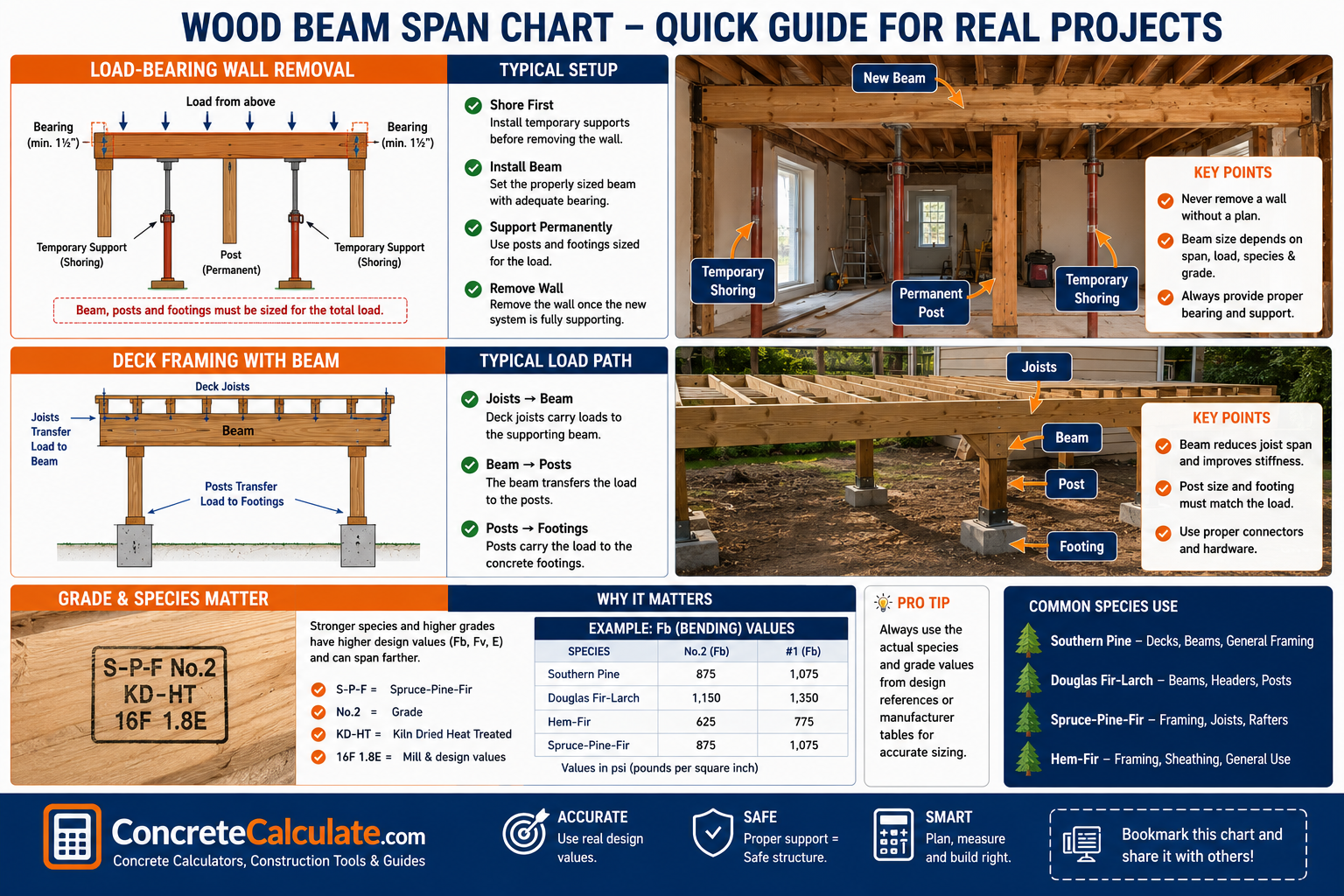
Deck joists transfer load to a beam, which transfers reactions to posts and footings. Use the Deck Beam Span Chart, Deck Joist Span Chart and Deck Footing Size Chart where applicable.
Garage openings
Large garage openings can support roof, wall and concentrated loads. Do not select a garage beam from a generic span number alone.
Load-bearing wall removal
Existing wall → temporary support → beam → posts → foundation. Temporary shoring, reactions, post capacity, footing capacity and existing foundation support are part of the project. See the Header Span Chart and Beam Size Chart.
Open-concept remodeling
Long openings may need more beam depth, designed posts and a verified support path to soil. Confirm what the existing wall supports before any removal.
⭐ Wood Beam Span by Species & Lumber Grade
Species and grade are design inputs, not labels to be guessed. Select lumber whose marked species and grade meet the required values for the chosen size.
| Selection Variable | Why It Changes Span Capacity | Examples |
|---|---|---|
| Species / species group | Different groups have different bending and stiffness properties | Southern Pine, Douglas Fir-Larch, Hem-Fir, Spruce-Pine-Fir |
| Grade | Visual grade affects reference design values | Select Structural, No.1, No.2, No.3 |
| Member size | Actual dressed breadth and depth affect section properties | Nominal 2×10 is not 2 by 10 actual inches |
| Adjustment factors | Loading duration, moisture, temperature, size and stability can modify values | Use the applicable NDS procedure |
Never assume all 2×12 lumber has the same capacity. AWC design methodology requires the selected species and grade to meet the required design values for the stated application.
⭐ Wood Beam Span: Fb, E, Shear & Deflection
A beam must be strong enough and stiff enough. Passing one check does not automatically pass the others.
| Term | Meaning | Why It Matters |
|---|---|---|
| Fb | Bending design value for extreme fibers | Helps determine resistance to bending moment |
| E | Modulus of elasticity | Controls stiffness and deflection behavior |
| Fv | Shear design value parallel to grain | Important near supports and at high reactions |
| Fc⊥ | Compression perpendicular to grain design value | Used to check bearing at supports |
| L/180 | Relatively permissive deflection criterion | Commonly associated with some roof or nonfinished conditions |
| L/240 | Intermediate serviceability criterion | Used for some structural elements and limited-storage conditions |
| L/360 | More restrictive deflection criterion | Common for occupied floors and finishes sensitive to movement |
| L/480 | Stricter serviceability criterion | May be selected where finishes or performance require it |
AWC explains that a member may avoid breaking but still deflect enough to create a bouncy floor or finish damage. Check the applicable deflection limit with the Beam Deflection Calculator.
Wood Beam Bearing, Tributary Width & Point Loads
Beam selection includes the supports and the loads delivered to them.
Bearing
At walls or posts, reaction forces create compression perpendicular to grain. Bearing length, support material, post alignment and the foundation beneath the post must be checked.
Tributary width
Tributary width is the portion of a floor or roof that transfers load to a beam. It is determined by framing geometry, commonly based on half the distance to the next parallel support on each side.
Point loads
A post above, a truss reaction, a wall reaction or a beam framing into the member can create a concentrated load. Uniform-load assumptions may not apply.
Beam orientation
Rectangular lumber must normally be installed with its larger dimension vertical for strong-axis bending. Flat orientation substantially reduces bending and stiffness performance unless explicitly designed.
Wood Beam Span by Number of Plies
Built-up beams are multiple members designed and connected to work together. Do not multiply a single member’s capacity without verifying the applicable built-up-member and connection assumptions.
| Configuration | Construction | Critical Checks |
|---|---|---|
| Single solid beam | One solid-sawn member | Species, grade, actual size, bearing and stability |
| Double-member beam | Two plies fastened together | Load sharing, fastener schedule, bearing and connection details |
| Triple-member beam | Three plies fastened together | Same checks plus installation sequence and support detail |
| Built-up beam at point load | Reaction may not distribute evenly without detailing | Connection and load-transfer design |
| Feature | Solid-Sawn Beam | Built-Up Beam |
|---|---|---|
| Construction | Single member | Multiple plies |
| Availability | Size-dependent | Often more flexible from standard lumber |
| Connections | Simpler member itself | Requires proper fastening and load transfer |
| Load sharing | One member | Depends on member and connection design |
| Design | Species and grade dependent | Member, connection, bearing and assembly dependent |
⭐ Solid Wood Beam vs LVL, Glulam, PSL & Steel
Engineered and steel alternatives may be useful when depth, long spans, consistent properties or high load capacity govern.
| Feature | Solid-Sawn Wood | LVL | Glulam | PSL / Steel |
|---|---|---|---|---|
| Material | Visually graded lumber | Veneer-based engineered lumber | Glued laminated timber | Engineered strand lumber / structural steel |
| Properties | Species and grade dependent | Consistent manufacturer-specific values | Designed engineered-timber values | Manufacturer-specific / steel design values |
| Long spans | Availability and depth can limit use | Often useful | Often useful, including architectural use | Often useful for demanding spans |
| Design source | NDS values and project conditions | Manufacturer literature and design requirements | Manufacturer literature and design requirements | Manufacturer or steel design requirements |
| Installation | Read grade stamp and orient properly | Follow manufacturer handling, holes and bracing rules | Follow manufacturer details | Heavier handling, connection and fire/corrosion considerations |
See the LVL Span Chart and Steel Beam Size Chart. Do not use LVL or steel tables to select a solid-sawn lumber beam.
Wood Beam Depth, Width & Lateral Stability
Depth generally influences bending resistance and stiffness more strongly than adding a small amount of width, but both dimensions and installation conditions matter.
Depth vs span
A deeper member has a larger section modulus and greater moment of inertia, which usually improves bending resistance and deflection performance. This is why increasing depth is often a powerful design option.
Width vs span
Increasing width can improve capacity and bearing area, but it does not have the same geometric influence as increasing vertical depth. Built-up width also requires proper connection design.
Compression-edge bracing
The compression edge needs lateral support to reduce lateral displacement and rotation. Joist attachment, blocking, sheathing and end restraint can be part of the stability system.
Lateral stability
AWC stability guidance identifies support of the compression edge and lateral support at bearing points as key assumptions. Do not remove bracing or rotate a beam without design review.
Wood Beam Span: Moisture, Exterior Use, Snow, Dead & Live Load
Exposure conditions and load duration can affect design values and durability requirements.
| Condition | Design / Durability Concern | Practical Check |
|---|---|---|
| Wet service / exterior | Moisture can require wet-service adjustments and increases decay risk | Use appropriate treated or naturally durable material and details |
| Decks and porches | Weather exposure, connections, posts and footings | Use exterior-rated materials and applicable deck provisions |
| Snow load | Local climate can govern roof design | Use locally applicable ground and roof snow requirements |
| Dead load | Permanent weight of framing, finishes, walls, roofing and equipment | Include all components supported by the beam |
| Live load | Occupants, furniture, storage or deck use | Use applicable code loading and deflection criteria |
| Load duration | Wood strength values may be adjusted by load duration | Use the appropriate NDS design procedure; E is not adjusted by load duration in the same way |
Wood Beam vs Header, Joist, Rafter & Ridge Beam
Choose the chart that matches the structural member and the load path.
| Member | Primary Role | Useful Internal Reference |
|---|---|---|
| Beam | Supports broader framing loads and transfers them to posts or walls | Beam Size Chart |
| Header | Typically supports framing above a wall opening | Header Span Chart |
| Floor joist | Repeated framing member carrying floor area to beams or walls | Floor Joist Span Chart |
| Roof rafter | Repeated roof framing member carrying roof load | Roof Rafter Span Chart |
| Ridge beam | Structural member receiving rafter reactions | Check rafter reaction, bearing and end supports |
| Ridge board | Alignment member, not automatically a structural ridge beam | Do not confuse it with a structural ridge beam |
Trusses can deliver concentrated reactions at bearing points. A beam below trusses should be designed for those actual reactions, not assumed to carry a uniform load unless the structural design supports that assumption.
⭐ Wood Beam Span Visual Guide
Original diagrams explaining span, load path, tributary width, loading pattern, beam depth, built-up members and bearing.
⭐ How to Read a Wood Beam Span Chart
Use a chart only when its headings match your project conditions.
Measure the design span as defined by the applicable method, not simply the stock lumber length.
Floor, roof, deck, wall, truss, header or a combination can produce different loads.
Identify dead, live and snow loads and distinguish distributed load from point reactions.
Match the load type, span and support assumptions. Do not use a joist table as a beam table.
The trial member must meet bending, stiffness and shear requirements.
Use actual commercially graded lumber values, not assumed generic wood values.
Check compression perpendicular to grain, bearing length, end support and compression-edge bracing.
Connections, plies, posts, foundations and soil must safely receive the reactions.
How to Calculate Wood Beam Span
This workflow follows the general logic used in AWC beam selection: start with actual conditions, then verify every applicable limit state.
Identify support locations and beam geometry.
Identify floor joists, rafters, trusses, walls or other members delivering load.
Convert tributary area into beam loading.
Use locally applicable design loading and combinations.
Include truss, post and framing reactions at actual locations.
Use actual available grade-stamped material.
Verify Fb, Fv and E with applicable factors and limits.
Verify Fc⊥, bearing length, compression-edge restraint and end support.
Design the entire load path to supporting soil.
⭐ Wood Beam Span Worked Examples
These examples show inputs and decision logic only. They intentionally do not state a final beam size without complete project assumptions and calculations.
1. Eight-Foot Wood Beam
2. Ten-Foot Wood Beam
3. Twelve-Foot Floor Beam
4. Sixteen-Foot Opening
5. Different Species and Grades
6. Roof Load vs Floor Load
7. Built-Up Wood Beam
Wood Beam Span Conversion Chart
Keep units consistent before entering a beam table or calculator.
| Conversion | Reference | Example |
|---|---|---|
| Feet to inches | Feet × 12 = inches | 10 ft = 120 in |
| Inches to feet | Inches ÷ 12 = feet | 144 in = 12 ft |
| Area load to line load | psf × tributary width in ft = plf | 50 psf × 8 ft = 400 plf |
| Uniform line load to total load | plf × loaded length in ft = lb | 400 plf × 10 ft = 4,000 lb |
| Total load to plf | Total lb ÷ loaded length in ft = plf | 4,000 lb ÷ 10 ft = 400 plf |
A conversion does not determine load distribution. A 4,000 lb point load and 400 plf over 10 feet have the same total weight but different effects on a beam.
Common Wood Beam Span Mistakes
A reliable beam choice requires the complete load path, not only the open distance.
❌ Sizing by span only
Beam size cannot be selected without load, tributary width, species, grade and deflection criteria.
❌ Ignoring point loads
Posts, trusses and other beam reactions can govern even when broad uniform load seems modest.
❌ Ignoring species and grade
Two members with the same nominal size can have different reference design values.
❌ Ignoring E and deflection
A beam may pass a strength check yet be too flexible for the use or finishes it supports.
❌ Ignoring shear and bearing
Support reactions, bearing length and compression perpendicular to grain must be checked.
❌ Using joist or LVL tables
Joist, rafter, solid lumber and engineered-wood tables are not interchangeable.
❌ Assuming plies simply multiply capacity
Built-up beams need proper connection and load-sharing design.
❌ Ignoring stability and moisture
Compression-edge bracing, exterior wet service, snow, decay and treatment requirements can change the design.
❌ Ignoring posts and footings
Every beam reaction must be safely carried through posts, foundations and soil.
❌ Mixing NDS editions
Use design values and provisions that belong to the same applicable NDS edition and project standard.
Frequently Asked Questions
📄 Download Wood Beam Span Chart PDF
Use the print button to create a print-ready or downloadable contractor and homeowner reference. For actual structural work, use a project-specific calculation and applicable local requirements.
Cite or Embed This Chart
Copy the page-wide citation to reference the complete Wood Beam Span Chart.