Roof Rafter Size Chart 2026 – 2×4 to 2×14 Selection Guide
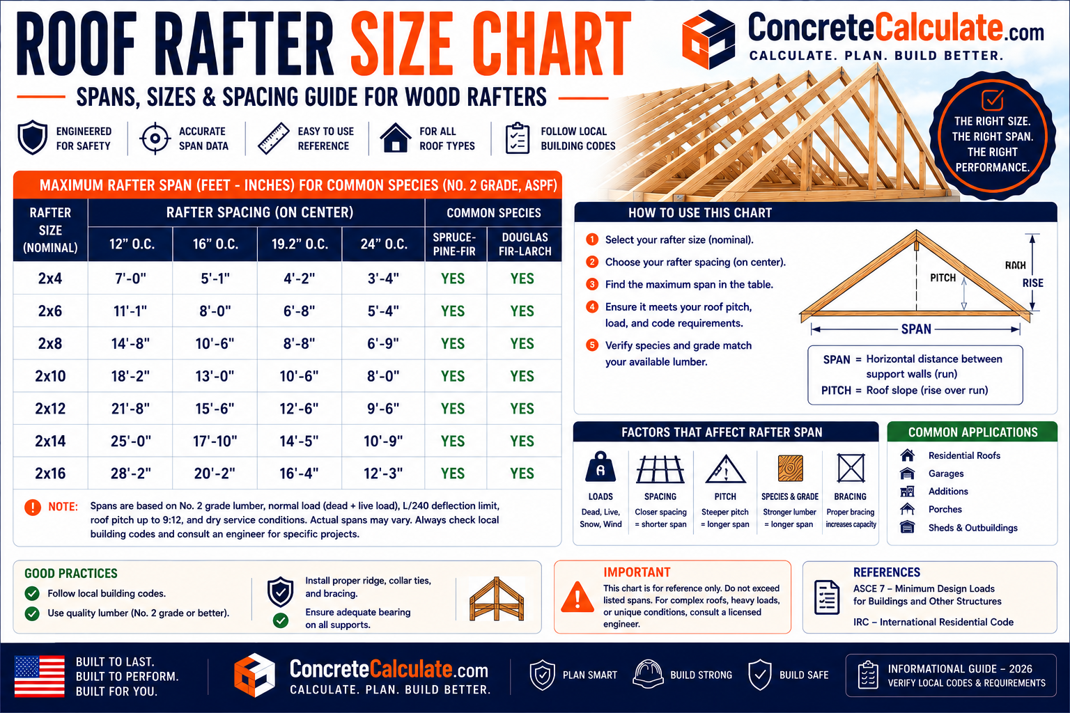
Roof Rafter Size Chart
2×4 to 2×14 Selection Guide
Rafter size is selected from horizontal projection, spacing, roof loads, deflection, species, grade and bearing, not from one universal size-to-span rule.
 Reviewed by Muhammad Ramzan Babar, PhD Researcher & Calculator Developer · View Profile
A rafter table must state the lumber species, grade, spacing, roof load, horizontal projection, deflection criterion, and support/bearing assumptions. This page uses explicit design conditions and selection logic rather than unsafe generic spans.
⭐⭐⭐ Roof Rafter Size Chart: Quick Reference
This is a selection matrix, not a list of generic spans. Use a specific AWC 2024 rafter table or the AWC span calculator after all variables are defined.
| Rafter Size | Species/Grade | Spacing | Roof Load | Horizontal Span | Deflection |
|---|---|---|---|---|---|
| 2×4 | Specified species/grade | 12″ OC | Specified DL + LL/Snow | Read applicable table | L/180 or L/240 |
| 2×6 | Specified species/grade | 16″ OC | Specified DL + LL/Snow | Read applicable table | L/180 or L/240 |
| 2×8 | Specified species/grade | 16″ OC | Specified DL + LL/Snow | Read applicable table | L/180 or L/240 |
| 2×10 | Specified species/grade | 16″ OC | Specified DL + LL/Snow | Read applicable table | L/180 or L/240 |
| 2×12 | Specified species/grade | 16″ OC | Specified DL + LL/Snow | Read applicable table | L/180 or L/240 |
| 2×14 | Specified species/grade | 16″ OC | Specified DL + LL/Snow | Read applicable table/design | Applicable criterion |
AWC explains that maximum horizontal rafter span is the smallest value calculated from bending strength (Fb), deflection/stiffness (E), and shear strength (Fv), using the specified lumber, spacing, total/live/snow load and deflection limit. Bearing and other conditions also require verification.
⭐⭐⭐ What Is a Roof Rafter?
A roof rafter is an inclined framing member that supports roof loads from the ridge area to the exterior wall bearing point.
Roof framing function
Rafters support roof sheathing, roofing material, snow/live load, wind load and other roof-related dead loads.
Ridge connection
Rafters connect at a ridge board or structural ridge beam depending on the roof framing system.
Wall bearing
Rafters bear at exterior walls or designed supports, transferring roof reactions into the building load path.
Ceiling relationship
Ceiling joists or rafter ties may resist outward rafter thrust in conventional framing, depending on their location and connection details.
⭐⭐⭐ Roof Rafter Size vs Roof Rafter Span
Size and span are different structural concepts.
| Term | Meaning |
|---|---|
| Rafter size | Lumber dimensions such as 2×4, 2×6, 2×8, 2×10, 2×12 or 2×14 |
| Rafter span | Structural horizontal projection the rafter is designed to span under specified conditions |
| Rafter length | Actual sloping physical length from ridge to bearing/overhang |
AWC rafter span tables use the horizontal projection of the rafter span, not the actual sloping rafter length. This is one of the most important distinctions on the page.
⭐⭐⭐ Roof Rafter Size vs Roof Truss Size
A 2×6 rafter is not the same design object as a 2×6 roof truss chord.
| Feature | Rafter | Roof Truss |
|---|---|---|
| Structural system | Individual framing member | Engineered multi-member assembly |
| Internal webs | No | Yes |
| Typical design | Prescriptive span table or engineering | Manufacturer/truss designer engineering |
| “2×6” meaning | Single member size | Could be chord/web size within complete truss system |
See the Roof Truss Span Chart for engineered truss guidance.
⭐⭐⭐ Roof Rafter Size vs Ceiling and Floor Joist Size
Using the wrong span table is a common framing mistake.
| Member | Primary Function | Typical Table Basis |
|---|---|---|
| Rafter | Supports roof loads | Horizontal projection, roof load, L/180 or L/240 |
| Ceiling joist | Supports ceiling loads | Ceiling/attic loading, L/240 |
| Floor joist | Supports occupancy loads | Floor load, L/360 |
| Roof truss | Engineered roof assembly | Truss-specific design drawing |
See the Ceiling Joist Span Chart and Floor Joist Span Chart for those separate systems.
⭐⭐⭐ Common Roof Rafter Sizes
Availability and suitability vary by species, grade, span, spacing, and loading.
| Rafter Size | General Design Consideration |
|---|---|
| 2×4 | Limited depth, generally for shorter projections under defined conditions |
| 2×6 | Common conventional rafter candidate |
| 2×8 | Greater depth improves bending and stiffness capacity |
| 2×10 | Longer-span conventional lumber candidate under stated loads |
| 2×12 | Higher depth option for larger projections/heavier loads |
| 2×14 | Larger conventional lumber where available; consider handling and engineered alternatives |
| 2×16 | Availability and practicality vary; full design check required |
2×6 rafter size ⭐⭐⭐
Selection requires spacing, species, grade, roof load and horizontal projection. Do not assign one universal span.
2×8 rafter size ⭐⭐⭐
A common choice where greater depth and stiffness are needed; still requires the full AWC table conditions.
2×10 and 2×12 rafters ⭐⭐⭐
Often considered for longer projections or heavier snow/dead loads, but no size should be selected without matching the actual design variables.
2×14 rafters
Useful for larger conventional lumber applications, but engineered lumber or structural ridge systems may become more practical as geometry and loads increase.
⭐⭐⭐ Roof Rafter Size by Spacing
Closer spacing shares roof load across more rafters; wider spacing increases tributary load per rafter.
| Spacing | Effect on Tributary Load | Rafter Selection Effect |
|---|---|---|
| 12″ OC | Lowest tributary width per rafter | Generally permits longer projection for same rafter/species/load condition |
| 16″ OC | Common residential baseline | Most frequently used reference spacing |
| 19.2″ OC | Intermediate tributary width | Use only where the selected table/design includes it |
| 24″ OC | Greatest load per rafter among common spacings | Generally reduces allowable projection for same design condition |
16″ OC rafters ⭐⭐⭐
A widely used residential spacing. Use an AWC table row matching 16″ spacing along with the correct species, grade, snow/live load, dead load and L/180 or L/240 condition.
24″ OC rafters ⭐⭐⭐
Wider spacing increases tributary roof area, requiring a different span table column or engineered calculation. Do not apply a 16″ OC span to a 24″ OC rafter.
⭐⭐⭐ Roof Rafter Size by Species, Grade and Design Values
Wood properties differ materially by species and grade.
| Design Value | Meaning | Selection Role |
|---|---|---|
| Fb | Bending design value | Resistance to roof-load bending moment |
| E | Modulus of elasticity | Stiffness and deflection control |
| Fc⊥ | Compression perpendicular to grain | Bearing at support locations |
| Fv | Shear design value | Resistance to shear near supports |
Species groups
Common U.S. species groups include Douglas Fir-Larch, Hem-Fir, Southern Pine and Spruce-Pine-Fir. They have different strength and stiffness properties, so species cannot be ignored.
Lumber grades
No. 2, No. 1, Select Structural and other grades have different design values. Grade affects Fb and often E, changing the allowable horizontal projection.
A 2×8 No. 2 Douglas Fir-Larch cannot automatically be assumed to have the same rafter span as a 2×8 No. 2 Southern Pine, Hem-Fir or Spruce-Pine-Fir. Species and grade must match the selected AWC table/design values.
⭐⭐⭐ Roof Rafter Deflection: L/180 vs L/240
Deflection is a serviceability condition separate from bending strength.
| Criterion | Meaning | Typical Context |
|---|---|---|
| L/180 | Maximum deflection = span ÷ 180 | Ceiling not directly attached to rafters |
| L/240 | Maximum deflection = span ÷ 240 | Ceiling attached to rafters, such as cathedral ceiling, where finish cracking concern is greater |
What L/240 means ⭐⭐⭐
Maximum deflection = span ÷ 240. For a 240 inch horizontal projection, L/240 allows 240 ÷ 240 = 1 inch of deflection under the specified load condition.
What L/180 means ⭐⭐⭐
Maximum deflection = span ÷ 180. For a 240 inch span, L/180 allows 1.33 inches, making it less restrictive than L/240.
Where ceiling finish is attached directly below rafters, such as a cathedral ceiling, the more restrictive L/240 criterion can apply to control visible cracking and finish damage. Use the table condition matching the actual ceiling configuration.
⭐⭐⭐ Roof Rafter Loads
Roof rafter selection requires fully stated loading conditions.
Dead load
Roof covering, underlayment, sheathing, insulation, ceiling, rafter self-weight, mechanical components and permanently attached materials.
Roof live load
Roof live load differs from floor occupancy live load and must follow the applicable code/design condition.
Snow load
Use the region-specific roof snow load. Ground snow load, drift, accumulation, roof geometry, exposure and thermal conditions all matter.
Wind load
Wind pressure, uplift, exposure, roof geometry, fasteners, connections and continuous load path must be separately designed; a downward-load span table is not complete wind design.
Roofing materials
Asphalt shingles, metal roofing, wood shakes, clay tile, concrete tile and slate can impose very different dead loads.
Solar loads
Panel weight, mounting, attachment points and wind uplift need evaluation against the existing roof framing design.
AWC’s current rafter span guidance includes roof live/snow load conditions in the 20 to 60 psf range and dead load conditions from 10 to 20 psf in its published tables. These are table design conditions, not universal code requirements; use the value applicable to the actual region and roof system.
Equipment for Your Project
Affiliate disclosure: As an Amazon Associate, ConcreteCalculate earns from qualifying purchases. We may also earn a commission from other affiliate links at no additional cost to you.
⭐⭐⭐ Roof Pitch, Horizontal Projection and Rafter Length
Pitch determines geometry, but horizontal projection is the span basis.
AWC rafter span tables use horizontal projection, not actual sloped rafter length. A 24 foot building does not automatically mean a 24 foot rafter span; use the ridge-to-wall horizontal projection, accounting for support geometry and ridge details.
Rise calculation
Rise = run x pitch. For a 12 foot horizontal run and 6:12 pitch: rise = 12 x 6/12 = 6 feet.
Rafter length calculation ⭐⭐⭐
Rafter length = square root of (run squared + rise squared). For a 12 foot run and 6 foot rise: √(12² + 6²) = 13.42 feet. This is physical rafter length, not allowable structural span.
Pitch effects
Pitch affects rise, rafter geometry, roof area, snow behavior and connection geometry, but not rafter size by itself.
Low and steep roof conditions
Low-slope roofs require material-specific drainage/roofing systems, while steep roofs have increased geometry, access and fall protection considerations.
See the Roof Pitch Chart for pitch-to-angle, slope factor and roof area calculations.
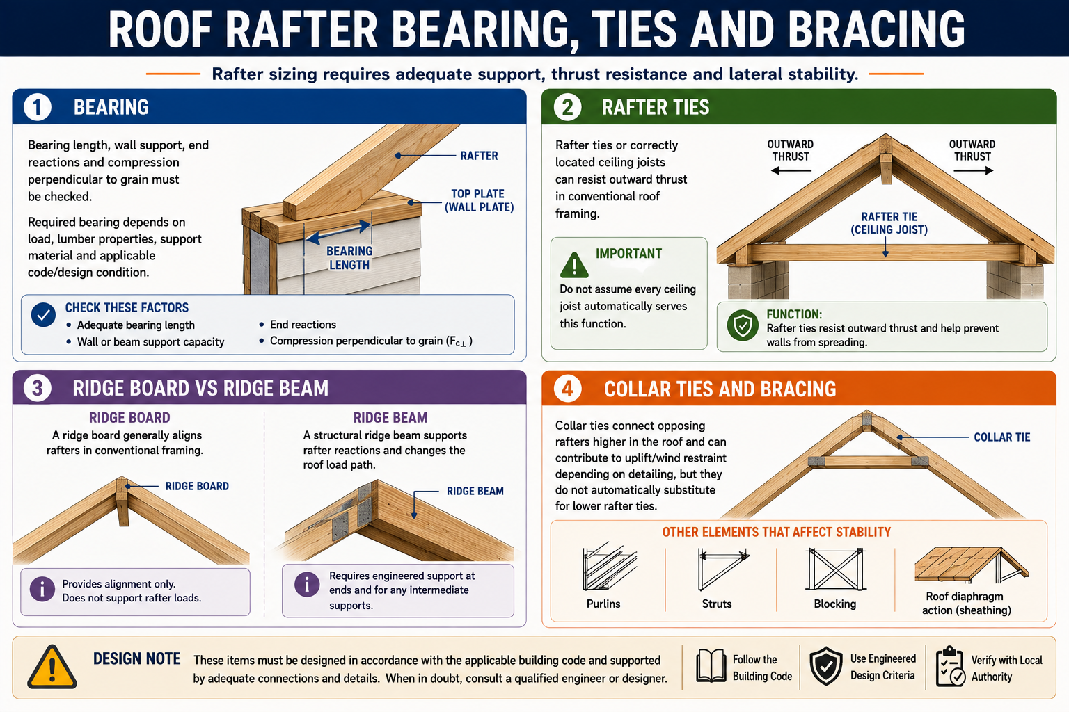
⭐⭐⭐ Roof Rafter Bearing, Ties and Bracing
Rafter sizing requires adequate support, thrust resistance and lateral stability.
Bearing
Bearing length, wall support, end reactions and compression perpendicular to grain must be checked. Required bearing depends on load, lumber properties, support material and applicable code/design condition.
Rafter ties
Rafter ties or correctly located ceiling joists can resist outward thrust in conventional roof framing. Do not assume every ceiling joist automatically serves this function.
Ridge board vs ridge beam
A ridge board generally aligns rafters in conventional framing. A structural ridge beam supports rafter reactions and changes the roof load path, requiring its own engineered support design.
Collar ties and bracing
Collar ties connect opposing rafters higher in the roof and can contribute to uplift/wind restraint depending on detailing, but they do not automatically substitute for lower rafter ties. Purlins, struts, blocking and roof diaphragm action can also affect stability.
See the Ceiling Joist Span Chart for the related ceiling/rafter tie framing system.
⭐⭐⭐ Roof Rafter Size for Long Spans and Engineered Lumber
Longer horizontal projections may call for a different framing strategy.
Long spans
Longer projections can require deeper conventional lumber, closer spacing, intermediate supports, structural ridge beams or engineered lumber, depending on the fully stated design condition.
Wide buildings
For 16, 20, 24, 30, 32 or 40 foot building widths, determine actual rafter horizontal projection, not building width alone, then design for the full load condition.
I-joists
Engineered I-joists require manufacturer-specific tables by product series, depth, spacing, loading and bearing. Do not use a sawn-lumber rafter table.
LVL and glulam
LVL, PSL and glulam can be considered for longer spans or structural ridge systems, but require manufacturer/design-specific information.
Roof trusses
Manufactured roof trusses may be used instead of conventional rafters, but are engineered triangulated systems designed as assemblies.
See the LVL Span Chart, Glulam Beam Size Chart, TJI Floor Joist Span Chart and Roof Truss Span Chart.
⭐⭐⭐ How to Choose Roof Rafter Size
The AWC-style selection workflow, not an arbitrary size recommendation.
Use ridge-to-wall horizontal distance, not sloping rafter length.
Confirm 12, 16, 19.2 or 24 inches OC.
Include roof covering, sheathing, underlayment, ceiling and other permanent loads.
Use the applicable local code/design load for the region.
Select L/240 where ceiling is attached; L/180 can apply where no ceiling is attached.
Use the actual lumber marking and appropriate design values.
Check bending strength and stiffness/deflection requirements.
Use the applicable AWC table or span calculator condition.
Verify bearing, ties, bracing, connections and any special load conditions.
⭐⭐⭐ 2024 Roof Rafter Span Tables and Code Requirements
Numerical tables must always identify edition and design condition.
AWC 2024 resources
AWC publishes 2024 Span Tables for Joists and Rafters and 2024 Design Values for Joists and Rafters. The tables are organized by species/grade, spacing, loads, deflection, and bearing assumptions.
Code and local amendments
The locally adopted IRC/IBC and local amendments govern actual projects. A span table is a prescriptive/reference tool under stated conditions, not a replacement for the applicable local code.
Maximum rafter span
There is no universal maximum roof rafter span. Maximum allowable span depends on size, species, grade, spacing, loads, horizontal projection, deflection and bearing conditions.
Moisture/service conditions
Service and moisture conditions can affect lumber design values and dimensions, so the appropriate adjusted values and code condition must be used.
⭐⭐⭐ Roof Rafter Size Visual Guide
Original diagrams explaining rafter anatomy, horizontal projection, and rafter selection variables.
See the itemized image list below for exact placement, subject and caption for each recommended photograph.
⭐⭐⭐ Roof Rafter Size Worked Examples
These examples show the selection workflow, not universal rafter approvals.
1. Defined Rafter Selection Example
2. Changing Spacing from 16″ to 24″ OC
3. Higher Snow Load
4. Cathedral Ceiling
5. Heavy Roofing
⭐⭐⭐ Common Roof Rafter Sizing Mistakes
Most incorrect rafter assumptions trace back to one of these errors.
❌ Using rafter length instead of horizontal projection
AWC rafter span uses horizontal projection, not sloped member length.
❌ Ignoring snow load
Region-specific snow can substantially change required rafter size.
❌ Ignoring species and grade
Different lumber has different Fb and E values.
❌ Ignoring spacing
16″ and 24″ OC conditions do not carry the same load per rafter.
❌ Using floor or ceiling joist tables
Rafter-specific loading and deflection conditions are required.
❌ Ignoring deflection
A rafter can pass bending but still be too flexible for an attached ceiling finish.
❌ Ignoring bearing
Support reaction and compression perpendicular to grain need verification.
❌ Assuming pitch determines size
Pitch changes geometry but loads, span, spacing and lumber properties control size.
❌ Assuming all 2×8 lumber has same capacity
Species and grade affect every table result.
❌ Using sawn lumber tables for I-joists
Engineered products require manufacturer-specific data.
❌ Adding solar or HVAC loads without review
Additional loads can exceed the original framing design.
❌ Treating this chart as engineering approval
Actual project design requires local code, complete loads, and qualified review where applicable.
Frequently Asked Questions
📄 Download Roof Rafter Size Chart PDF
This PDF is a selection reference, not a generic span list. Each numerical table must retain species, grade, spacing, load, horizontal projection, deflection, bearing and source edition basis.
Cite or Embed This Chart
Copy the page-wide citation to reference the complete Roof Rafter Size Chart.