Concrete Anchor Spacing Chart – Minimum Spacing and Edge Distance
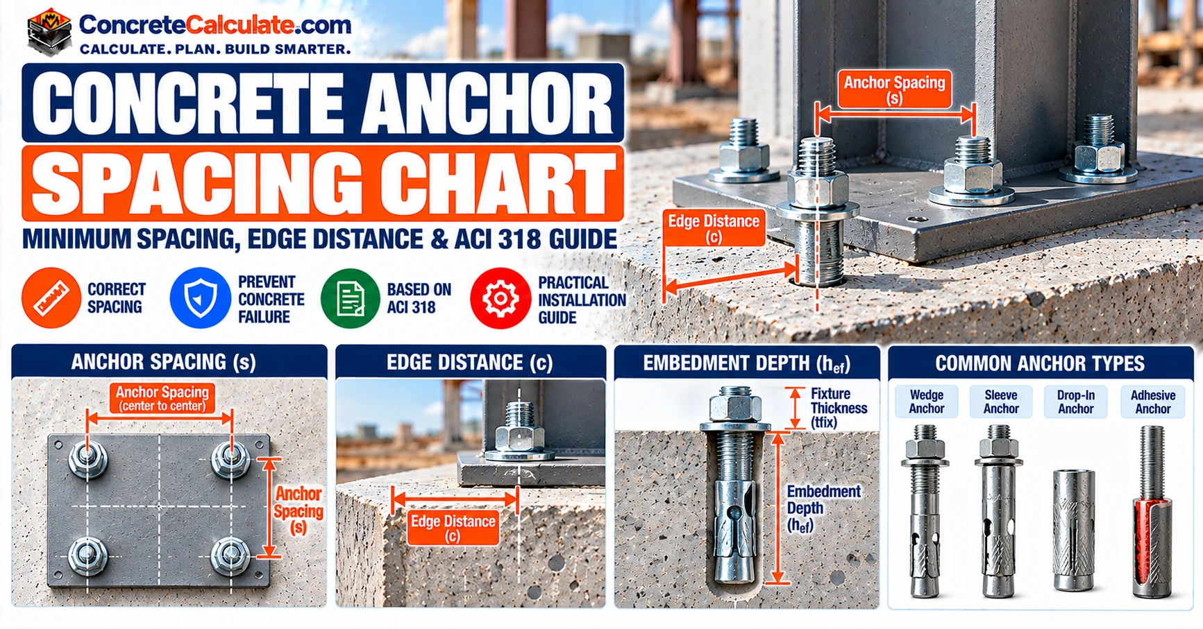
Concrete Anchor Spacing ChartMinimum Spacing and Edge Distance
A technical reference for contractors, engineers, installers and inspectors: minimum versus critical spacing, edge distance, embedment, anchor groups and a verified manufacturer example from Hilti KWIK BOLT TZ2 data.
Jump to the Chart Reviewed by Muhammad Ramzan Babar, PhD Researcher (Plasma Physics) & Calculator Developer, View Profile
Key Facts
- No universal minimum spacing exists. It depends on the anchor system, embedment, edge distance, concrete thickness and installation conditions.
- Minimum installation spacing, critical breakout spacing (3hef) and maximum layout spacing are three different concepts.
- Example: Hilti KB-TZ2 3/8 in., 2 in. embedment, needs 2-1/2 in. edge distance with 6 in. spacing (Case A) or 2-1/4 in. spacing with a 3-1/2 in. edge distance (Case B).
Concrete Anchor Spacing Chart: Quick Reference
Minimum spacing and edge distance for a manufacturer-identified expansion anchor, with the three spacing concepts explained.
There is no universal minimum spacing for concrete anchors. Permitted spacing depends on the anchor system, embedment, edge distance, concrete thickness and installation conditions, so this chart gives one manufacturer-identified example instead of a generic rule. For sill-plate bolts in residential foundations, see the separate Anchor Bolt Spacing Chart; this page covers engineered concrete anchor groups.
How to Read This Chart
Pick the row for your anchor diameter and effective embedment. Then choose Case A or Case B and meet both numbers in the same case. Case A allows a smaller edge distance if spacing is large. Case B allows a smaller spacing if the edge distance is large. A chart value is valid only for its stated product, embedment, concrete thickness and installation conditions.
| Anchor diameter | Effective embedment hef | Minimum concrete thickness h | Case A: min. edge distance c | Case A: spacing s at least | Case B: min. spacing s | Case B: edge distance c at least |
|---|---|---|---|---|---|---|
| 1/4 in. | 1-1/2 in. | 3-1/4 in. | 1-1/2 in. | 1-1/2 in. | 1-1/2 in. | 1-1/2 in. |
| 3/8 in. | 2 in. | 4 in. | 2-1/2 in. | 6 in. | 2-1/4 in. | 3-1/2 in. |
| 1/2 in. | 2 in. | 4 in. | 2-3/4 in. | 5-1/2 in. | 3-1/2 in. | 10 in. |
- Values apply only to the stated Hilti KB-TZ2 carbon-steel configurations. Do not apply them to wedge anchors from other manufacturers, concrete screws, adhesive anchors or cast-in-place bolts.
- Effective embedment hef is not the same as nominal embedment hnom or the drilled hole depth.
- Meeting the minimum geometry does not establish tension or shear capacity. Cracked-concrete, seismic and group requirements are checked separately.
- Interpolation between the two cases is permitted for this product; see the Hilti example below. Check the current product data and evaluation report before use.
Source: Hilti KWIK BOLT TZ2 (KB-TZ2) carbon steel. Data edition: ICC-ES ESR-4266 (reissued December 2023, revised October 2024), Table 3, and Hilti North American Product Technical Guide, Volume 2, Edition 22, Table 5. Units are inches. The 1/2 in. row uses hef = 2 in.; the 1/2 in. anchor has other embedments listed in the diameter section.
Planning your next concrete project?
Plan concrete materials and project costs with our downloadable Excel estimator pack. For estimating only; follow applicable technical standards for design and installation.
One-time purchase · Digital downloadWhat Is Concrete Anchor Spacing?
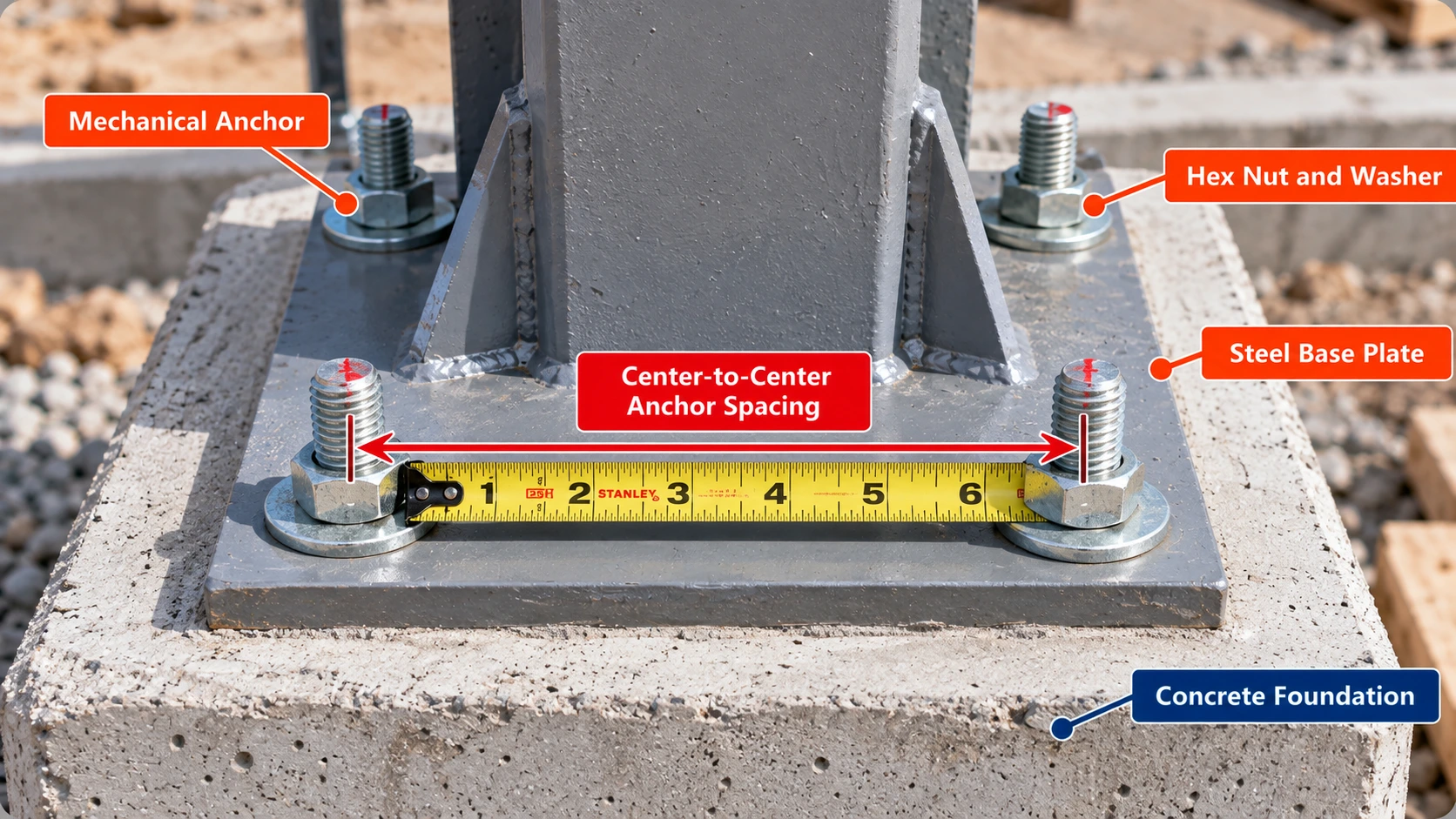
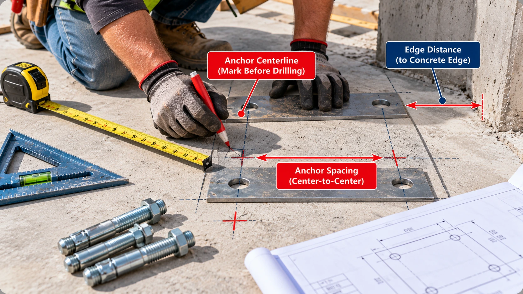
Anchor spacing is the distance between adjacent anchors, always measured from one anchor centerline to the next. It controls how much concrete each anchor shares, whether the concrete can split during setting, and how anchors behave as a group.
Center-to-Center Spacing
If two anchor centerlines sit at positions x1 and x2 along the same line, the spacing is s = |x2 – x1|. This is a measurement, not a design approval.
Clear Spacing
Clear spacing is the free distance between anchor bodies: s_clear = s – da. It is a nominal shaft calculation and does not account for oversized holes, expansion components, washers or base-plate holes.
Why Spacing Matters
Close anchors can overlap their concrete breakout regions, concentrate expansion forces and share load unevenly. Maximum layout spacing, such as a sill-plate bolt limit, is a different idea from minimum structural spacing.
| Symbol | Meaning | Measurement |
|---|---|---|
| da | Nominal anchor diameter | Diameter |
| s | Actual anchor spacing | Center to center |
| s_min | Minimum permitted spacing | Product and design specific |
| scr,N | Characteristic tension breakout spacing | 3hef in the simplified ACI model |
| c | Actual edge distance | Anchor center to concrete edge |
| c_min | Minimum permitted edge distance | Product and design specific |
| hef | Effective embedment depth | As defined for the anchor system |
| hnom | Nominal embedment depth | Manufacturer defined |
| h | Concrete member thickness (h_min is the minimum) | Product and design specific |
| f’c | Specified concrete compressive strength | psi or MPa |
Concrete Anchor Spacing Standards and Codes
Three layers of rules decide anchor spacing: the structural design code, the qualification standard that tests the product, and the evaluation report for the exact product. All three can apply to one anchor.
| Document | Role | Typical content |
|---|---|---|
| ACI 318 Chapter 17 | Structural design of anchors to concrete | Tension, shear, breakout, pullout, groups, edge distance, thickness, interaction, seismic |
| ACI 355.2 | Qualification of post-installed mechanical anchors | Test requirements and performance categories, including cracked concrete |
| ACI 355.4 | Qualification of post-installed adhesive anchors | Test requirements for adhesive anchor systems |
| ICC-ES evaluation report | Product-specific recognition | Approved sizes, embedments, spacing, edge distance, thickness and limits |
| Manufacturer data | Product installation instructions | Hole preparation, torque, embedment, hardware and conditions of use |
ACI 318 Chapter 17
ACI 318 Chapter 17, Anchoring to Concrete, sets strength design for cast-in and post-installed anchors. It covers concrete breakout, group effects, edge distances, spacings and thicknesses (Section 17.9 in ACI 318-19), tension and shear interaction (17.8) and seismic design (17.10). The 2024 IBC references ACI 318-19. Section numbers change between editions, so confirm clauses against the edition your project adopts.
ACI 355.2 and ACI 355.4
These standards qualify post-installed mechanical and adhesive anchors. They do not replace the design provisions in ACI 318. They are the reason a product can publish its own minimum spacing and edge distance.
ICC-ES Evaluation Reports
For post-installed anchors, an evaluation report often states that its tabulated minimum spacing, edge distance and member thickness are used in place of the default ACI values. The Hilti KB-TZ2 report, ESR-4266, says exactly that.
Local Adoption Controls
The locally adopted code edition, project specifications, the current evaluation report and the approved structural design govern any anchor layout.
Minimum vs. Critical Anchor Spacing
These are different ideas, and mixing them up is the most common error in anchor spacing articles.
| Concept | Meaning | Where it comes from |
|---|---|---|
| Minimum installation spacing (s_min) | Smallest permitted center-to-center distance under the product qualification | Product data, evaluation report, ACI 318 |
| Critical breakout spacing (scr,N) | 3hef in the simplified tension breakout model, where projected areas stop overlapping | ACI 318 breakout geometry |
| Actual installed spacing (s) | The distance you measure on the slab | Your layout |
| Maximum layout spacing | Largest allowed gap between anchors, such as a sill-plate rule | Residential code or design drawings |
Minimum Installation Spacing
A product’s minimum spacing comes from testing. It prevents splitting and installation damage for that product. It often depends on edge distance, as the Hilti cases show.
Critical Breakout Spacing
In ACI’s tension breakout model, the projected breakout area extends about 1.5hef from the anchor axis in each direction, so two anchors 3hef apart have projected areas that just meet. This describes group interaction in one failure mode, not an installation limit.
Actual Installed Spacing
An installed layout can satisfy the product’s minimum spacing and still lose breakout resistance because adjacent breakout regions overlap. Passing the minimum check is not enough; the governing failure modes must be checked.
Concrete Anchor Spacing by Anchor Type
Each anchoring mechanism loads the concrete differently, so no single 4d, 6d or 10d rule can safely represent all of them.
| Anchor family | How to establish minimum spacing | Main caution |
|---|---|---|
| Cast-in headed anchors | ACI 318 design and project geometry | Breakout, splitting and reinforcement |
| Torque-controlled expansion anchors | Current manufacturer data and evaluation report | Expansion-induced splitting |
| Drop-in anchors | Product-specific qualification and setting requirements | Installation and expansion effects |
| Concrete screw anchors | Product-specific evaluation and design | Installation and concrete breakout |
| Adhesive anchors | Product qualification, ACI design and installation requirements | Bond, edge effects and group behavior |
| Undercut anchors | Product qualification and ACI design | Mechanical interlock and breakout |
Mechanical Anchors
Expansion anchors press against the hole wall, which can split concrete when anchors or edges are too close. Use the product’s evaluated spacing. Dimensions and types are in the Anchor Bolt Size Chart.
Adhesive Anchors
Bonded threaded rods transfer load through adhesive, so bond failure and concrete breakout both matter. Spacing comes from the adhesive system’s qualification and ACI 318 design.
Cast-In-Place Anchors
Headed bolts and studs are designed from geometry, load and concrete properties, with ACI 318 minimum spacing and edge distance as a floor, not a design.
Concrete Anchor Spacing by Diameter
Diameter-based searches usually want one number. The honest answer is a set of numbers tied to embedment. The table below lists every carbon-steel KB-TZ2 combination for 1/4 through 3/4 in. diameters, and the second table shows why a diameter multiple fails even within one product.
| Diameter | hef | h min. | Case A: c min. | Case A: s at least | Case B: s min. | Case B: c at least |
|---|---|---|---|---|---|---|
| 1/4 in. | 1-1/2 | 3-1/4 | 1-1/2 | 1-1/2 | 1-1/2 | 1-1/2 |
| 3/8 in. | 1-1/2 | 3-1/4 | 5 | 8 | 5 | 8 |
| 3/8 in. | 2 | 4 | 2-1/2 | 6 | 2-1/4 | 3-1/2 |
| 3/8 in. | 2-1/2 | 5 | 2-1/2 | 5 | 2 | 4 |
| 1/2 in. | 1-1/2 | 3-1/2 | 8 | 12 | 12 | 8 |
| 1/2 in. | 2 | 4 | 2-3/4 | 5-1/2 | 3-1/2 | 10 |
| 1/2 in. | 2-1/2 | 5 | 2-3/4 | 9-3/4 | 3 | 8 |
| 1/2 in. | 3-1/4 | 5-1/2 | 2-1/4 | 5-1/4 | 2 | 4-3/4 |
| 5/8 in. | 2-3/4 | 5 | 4-1/2 | 6-1/2 | 4-1/2 | 5-1/2 |
| 5/8 in. | 3-1/4 | 5-1/2 | 3-1/2 | 5-1/2 | 2-3/4 | 7 |
| 5/8 in. | 4 | 6 | 2-3/4 | 7-1/4 | 2-1/4 | 4-1/4 |
| 3/4 in. | 3-1/4 | 5-1/2 | 5 | 10 | 4-1/2 | 6 |
| 3/4 in. | 3-3/4 | 6 | 4 | 5-3/4 | 3-3/4 | 7-1/4 |
| 3/4 in. | 4-3/4 | 8 | 3-1/2 | 5-1/2 | 3-3/4 | 4-3/4 |
Source: Hilti KWIK BOLT TZ2 (KB-TZ2) carbon steel. Data edition: ICC-ES ESR-4266 (reissued December 2023, revised October 2024), Table 3, and Hilti North American Product Technical Guide, Volume 2, Edition 22, Table 5.
1/4- and 3/8-Inch Anchors
The 1/4 in. anchor lists 1-1/2 in. for both edge and spacing at 1-1/2 in. embedment. The 3/8 in. anchor ranges from 2 in. to 8 in. depending on embedment and case. At 2 in. embedment its minimum spacing is 2-1/4 in. only when the edge distance is at least 3-1/2 in.
1/2-Inch Anchors
At 2 in. embedment, the 1/2 in. anchor needs 3-1/2 in. spacing with a 10 in. edge distance (Case B) or a 2-3/4 in. edge distance with 5-1/2 in. spacing (Case A). Other embedments change both numbers, so identify hef first.
5/8- and 3/4-Inch Anchors
Larger diameters use deeper embedments and larger distances. Compare rows within one embedment only.
| Anchor | Case A spacing | Case B spacing | Case A edge | Case B edge |
|---|---|---|---|---|
| 3/8 in., hef 2 in. | 16.0da (6 in.) | 6.0da (2-1/4 in.) | 6.7da (2-1/2 in.) | 9.3da (3-1/2 in.) |
| 1/2 in., hef 2 in. | 11.0da (5-1/2 in.) | 7.0da (3-1/2 in.) | 5.5da (2-3/4 in.) | 20.0da (10 in.) |
| 1/4 in., hef 1-1/2 in. | 6.0da (1-1/2 in.) | 6.0da (1-1/2 in.) | 6.0da (1-1/2 in.) | 6.0da (1-1/2 in.) |
Anchor products, drill sizes and installation are covered in the Wedge Anchor Size Chart and the Concrete Anchor Drill Bit Size Chart.
Concrete Anchor Edge Distance Chart
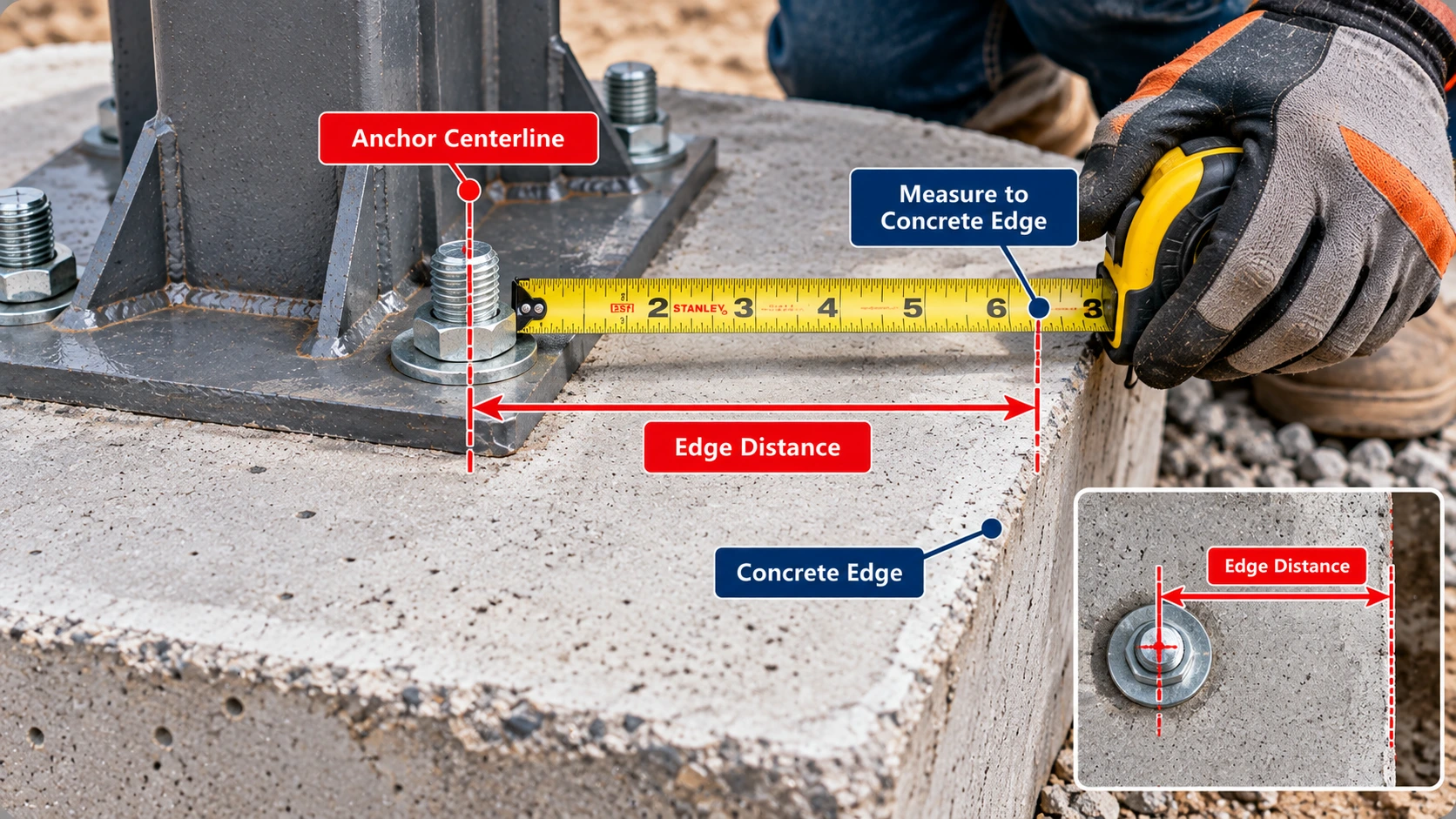
Concrete edge distance is measured from the anchor centerline to the nearest free concrete edge. It is not the distance to a steel base-plate edge, a fixture hole, a sill-plate end, reinforcement or the clear spacing between anchors.
Minimum Edge Distance
The minimum edge distance is the smallest value permitted for installation, and for a product like the KB-TZ2 it depends on spacing.
Critical Edge Distance
Critical edge distance cac is different: it is the distance beyond which edge effects on splitting no longer reduce uncracked concrete breakout strength where supplementary reinforcement is absent. For the 3/8 in. KB-TZ2 at 2 in. embedment, the minimum edge distance is 2-1/2 in. but cac is 4-3/8 in. When c is less than cac, ESR-4266 requires a further reduction factor.
| Anchor | Case A minimum edge distance | Case B edge distance for min. spacing | Critical edge distance cac |
|---|---|---|---|
| 3/8 in., hef 2 in. | 2-1/2 in. (with s at least 6 in.) | 3-1/2 in. (with s at least 2-1/4 in.) | 4-3/8 in. |
| 1/2 in., hef 2 in. | 2-3/4 in. (with s at least 5-1/2 in.) | 10 in. (with s at least 3-1/2 in.) | 5-1/2 in. |
Source: Hilti KWIK BOLT TZ2 (KB-TZ2) carbon steel. Data edition: ICC-ES ESR-4266 (reissued December 2023, revised October 2024), Table 3, and Hilti North American Product Technical Guide, Volume 2, Edition 22, Table 5.
Measuring Concrete Edges
Measure to every relevant free edge, including slab ends, openings and re-entrant corners. In a corner, two edge distances apply at once.
How Edge Distance Affects Anchor Spacing
For many anchors, the minimum spacing and the minimum edge distance cannot be chosen independently. The Hilti KB-TZ2 lists two permitted combinations, and a layout must satisfy both numbers of one combination.
Conditional Manufacturer Limits
Case A favors a smaller edge distance; Case B favors a smaller spacing. Hilti advises following the other parameter in whichever case you use, and mixing the cases is not recommended.
Hilti KB-TZ2 Examples
| Installation case | Actual edge distance | Actual anchor spacing | Preliminary geometry result |
|---|---|---|---|
| A | 2-1/2 in. | 6 in. | Meets published Case A limits |
| B | 3-1/2 in. | 2-1/4 in. | Meets published Case B limits |
| C | 2-1/2 in. | 2-1/4 in. | Cannot be accepted by combining the two cases |
| D | 4 in. | 6 in. | Exceeds both conditional minimum combinations |
| E | 3 in. | 4-1/2 in. | Permitted by interpolation (minimum s at c = 3 in. is 4-1/8 in.) |
Source: Hilti KWIK BOLT TZ2 (KB-TZ2) carbon steel. Data edition: ICC-ES ESR-4266 (reissued December 2023, revised October 2024), Table 3, and Hilti North American Product Technical Guide, Volume 2, Edition 22, Table 5.
Interpolation Requirements
ESR-4266 permits additional combinations by linear interpolation between the two boundary values, and Hilti’s technical guide gives the same method. The straight-line calculation below shows how.
Interpolating Between Case A and Case B
Variables: c1, s1 = Case A edge distance and spacing; c2, s2 = Case B edge distance and spacing; c = actual edge distance between c1 and c2
Practical interpretation: The permitted spacing climbs smoothly from 2-1/4 in. at a 3-1/2 in. edge distance to 6 in. at a 2-1/2 in. edge distance. Interpolation applies only between the two published cases, never outside them.
Anchor Embedment Depth and Spacing
Effective vs. Nominal Embedment
Spacing formulas use effective embedment hef, which is not the same as nominal embedment hnom or the drilled depth. Using the wrong depth shifts every breakout calculation.
| Term | Meaning | Value |
|---|---|---|
| Effective embedment hef | Effective embedment depth used in design, as the manufacturer defines it | 2 in. |
| Nominal embedment hnom | Manufacturer-defined installed depth | 2-1/2 in. |
| Minimum hole depth ho | Drilled depth required | 2-3/4 in. |
Source: Hilti KWIK BOLT TZ2 (KB-TZ2) carbon steel. Data edition: ICC-ES ESR-4266 (reissued December 2023, revised October 2024), Table 3, and Hilti North American Product Technical Guide, Volume 2, Edition 22, Table 5. (Table 1, setting information).
Critical Spacing Formula
The standard tension breakout model projects a region of about 1.5hef from the anchor axis. Two anchors whose projected regions just meet are 2 × 1.5hef = 3hef apart.
| Effective embedment hef | 1.5hef projected distance | 3hef characteristic spacing |
|---|---|---|
| 1-1/2 in. | 2-1/4 in. | 4-1/2 in. |
| 2 in. | 3 in. | 6 in. |
| 2-1/2 in. | 3-3/4 in. | 7-1/2 in. |
| 3 in. | 4-1/2 in. | 9 in. |
| 4 in. | 6 in. | 12 in. |
| 5 in. | 7-1/2 in. | 15 in. |
| 6 in. | 9 in. | 18 in. |
Worked Example
Characteristic Tension Breakout Spacing
Variables: scr,N = characteristic spacing (in.); hef = effective embedment depth (in.)
Practical interpretation: Twelve inches is where the idealized projected areas stop overlapping for tension breakout. It is not necessarily the minimum permitted installation spacing, and it does not cover splitting, shear, bond or complete group capacity.
Concrete Thickness and Anchor Spacing
An anchor can meet its spacing and edge-distance requirements and still be wrong for a thin member. The minimum thickness comes from the product data or the governing design, never from the spacing chart.
Minimum Member Thickness
For the KB-TZ2, ESR-4266 lists minimum thickness by diameter and embedment and requires it in place of the default ACI value. A larger spacing does not substitute for adequate thickness.
Hole Depth
The hole is deeper than the embedment, so the concrete left below the hole is smaller than the slab thickness suggests. For a 3/8 in. anchor at 2 in. embedment in a 4 in. slab, the hole is 2-3/4 in. deep and 1-1/4 in. of concrete remains.
| Diameter | hef | Min. thickness h | Min. hole depth ho | Concrete left below hole (h – ho) |
|---|---|---|---|---|
| 3/8 in. | 2 in. | 4 in. | 2-3/4 in. | 1-1/4 in. |
| 3/8 in. | 2-1/2 in. | 5 in. | 3-1/4 in. | 1-3/4 in. |
| 1/2 in. | 2 in. | 4 in. | 2-3/4 in. | 1-1/4 in. |
| 1/2 in. | 2-1/2 in. | 5 in. | 3-1/4 in. | 1-3/4 in. |
Source: Hilti KWIK BOLT TZ2 (KB-TZ2) carbon steel. Data edition: ICC-ES ESR-4266 (reissued December 2023, revised October 2024), Table 3, and Hilti North American Product Technical Guide, Volume 2, Edition 22, Table 5. Remaining concrete is calculated.
Thin Concrete Members
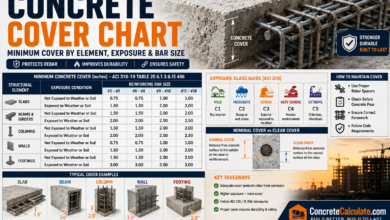
Check reinforcement, post-tensioning and embedded services before drilling a thin slab or wall. Cover values alone do not show where it is safe to drill. See the Concrete Cover Chart for reinforcement cover context.
Cracked vs. Uncracked Concrete
Concrete may be treated as cracked or uncracked for anchor design depending on the structure and analysis. The assumption changes which products can be used and how much resistance they have.
| Item | What changes | What to check |
|---|---|---|
| Product qualification | Anchors are tested and qualified for cracked, uncracked or both conditions | Check the evaluation report for the exact product |
| Design resistance | Breakout and pullout use different effectiveness factors for cracked and uncracked concrete | Do not use uncracked data in cracked concrete |
| Seismic design | Seismic design requires anchors qualified for seismic loading and the ACI seismic provisions | ACI 318 Section 17.10 and the product report |
| Concrete strength | Reports state a permitted f’c range | KB-TZ2: 2,500 to 8,500 psi per ESR-4266 |
Qualification
The KB-TZ2 is evaluated for cracked and uncracked concrete and Seismic Design Categories A through F. Some products are qualified for uncracked concrete only, so approval cannot be inferred from the anchor’s diameter or appearance.
Design Resistance
The KB-TZ2’s minimum spacing and edge-distance table is the same for both conditions, but its design strength uses separate cracked and uncracked factors. The concrete must reach its minimum design strength before anchors are installed; see the Concrete PSI Chart for strength classes.
Seismic Considerations
Seismic loading requires ACI 318 Section 17.10 provisions and a seismic-qualified anchor.
Mechanical Expansion Anchor Spacing
Torque-controlled anchors, such as wedge and sleeve anchors, expand when the nut is tightened. Displacement-controlled anchors, such as drop-in anchors, expand when a setting tool drives an internal plug. Both push outward on the hole wall.
Wedge Anchors
The KB-TZ2 is a torque-controlled expansion anchor. Its spacing and edge distance come from its evaluation report, as shown in the main chart. See the Wedge Anchor Size Chart for dimensions and installation.
Sleeve Anchors
Sleeve anchors spread load along a sleeve and use product-specific spacing. Check the Sleeve Anchor Size Chart and the manufacturer’s data.
Drop-In Anchors
Drop-in anchors have an internal thread and set by driving an expansion plug. See the Drop-In Anchor Size Chart and the product’s setting requirements.
Expansion-Induced Splitting
Expansion pressure can split concrete when edge distance or spacing is too small, which is why products publish minimums. Use the manufacturer’s evaluated numbers, not a diameter multiple.
Concrete Screw Anchor Spacing
Concrete screws cut their own threads into a drilled hole, so their geometry, hole size and embedment are product-specific. The Concrete Screw Size Chart covers dimensions.
Installation Requirements
Use the specified bit, hole depth and cleaning method, and follow the manufacturer’s instructions on whether a screw may be removed and reinstalled.
Minimum Spacing
Concrete screws publish their own minimum spacing by diameter and embedment. Do not assume the minimum spacing for a wedge anchor applies to a screw.
Edge Distance
Edge distance, member thickness and concrete breakout also come from the screw’s evaluation report and ACI 318 design.
Adhesive Anchor Spacing
Adhesive anchors are threaded rods or rebar set in a drilled hole with an approved adhesive.
Bonded Threaded Rods
Use an adhesive system qualified under ACI 355.4 with suitable threaded elements, correct hole diameter and cleaning, and the specified cure time and temperature. Material grades are in the Anchor Bolt Grade Chart.
Group Effects
Adhesive anchors can fail by concrete breakout, by bond failure, or by steel failure. The bond influence area can overlap at spacings that do not overlap the concrete breakout region, so both are checked. Minimum installation spacing is a different matter from calculated group strength.
Installation Conditions
Hole cleaning, moisture, temperature and cure time change performance. Follow the product report and instructions exactly.
Cast-In-Place Anchor Spacing
Cast-in anchors are set before the concrete is placed. Their spacing and edge distance come from design geometry, load and ACI 318, and reinforcement can change breakout behavior.
Headed Anchors
ACI 318-19 sets minimum geometry for headed bolts, shown below. These are lower bounds, and design usually requires much more.
| Parameter | Anchors not torqued | Anchors torqued |
|---|---|---|
| Minimum center-to-center spacing | 4da | 6da |
| Minimum edge distance | Cover for reinforcement per ACI 318 Section 20.5.1.3 | 6da |
Anchor Rod Groups
Anchor rod groups under steel columns are designed for tension, shear and breakout as a group. Reinforcement, headed-stud details and anchor material affect the result.
Concrete Breakout
The same 1.5hef breakout geometry applies to cast-in headed anchors. Do not use post-installed anchor installation tables for cast-in anchors.
Concrete Anchor Group Effects
A group of anchors does not simply multiply one anchor’s capacity. When breakout regions overlap, the shared concrete is counted once, so four anchors do not give four times the strength of one isolated anchor.
Two-Anchor Groups
Two anchors spaced closer than 3hef share part of their projected area, as the earlier diagram shows.
Four-Anchor Groups
Four-anchor patterns overlap in both directions, and base plates add load eccentricity.
Overlapping Breakout Regions
Projected Breakout Area for a Two-Anchor and a Four-Anchor Group (reference geometry)
Variables: hef = effective embedment; s, sx, sy = center-to-center spacings; ANco = 9hef² for one isolated anchor; group value is limited to n × ANco
Practical interpretation: This is a geometric reference ratio from the simplified model. The group strength also needs edge, eccentricity, cracking and other ACI factors, so do not read these ratios as capacity.
Group Eccentricity
When the load is not centered on the group, anchors carry unequal shares and ACI applies an eccentricity factor.
Equipment for Your Project
Affiliate disclosure: As an Amazon Associate, ConcreteCalculate earns from qualifying purchases. We may also earn a commission from other affiliate links at no additional cost to you.
Concrete Anchor Spacing Under Tension
Tension spacing is mainly a breakout question: how much concrete the anchors engage and whether their regions overlap.
Concrete Breakout
ACI 318 calculates breakout strength from the projected area compared with the single-anchor reference area, then applies modification factors. For the KB-TZ2, ESR-4266 requires ACI 318-19 Section 17.6.2 with its own effectiveness factors for cracked and uncracked concrete.
Projected Area
Reference Projected Breakout Area for One Anchor
Variables: ANco = projected tension breakout area of a single anchor far from edges (in²); hef = effective embedment (in.)
Practical interpretation: This is a geometric quantity, not a strength value. Group projected areas, edge truncation, eccentricity and other ACI factors require the governing code procedure, so do not use it to claim an allowable load.
Strength Limitations
Steel strength and pullout strength can govern instead of breakout. The design strength is the lowest of all applicable failure modes, and spacing is only one input.
Concrete Anchor Spacing Under Shear
Shear is governed by the edge, not by the 3hef relationship. Tension characteristic spacing does not apply as a universal shear-spacing rule.
Shear Toward a Concrete Edge
An anchor loaded toward a nearby free edge can break out a wedge of concrete toward that edge. Edge distance in the load direction is the key variable.
Reference Projected Shear Breakout Area, Single Anchor Near an Edge
Variables: AVco = reference projected shear breakout area (in²); ca1 = edge distance in the shear direction (in.)
Practical interpretation: The shear area grows with the square of the edge distance, which is why edge distance dominates shear. This is reference geometry only, not a strength or a spacing rule. Confirm the formula in the adopted ACI 318 edition.
Shear Parallel to an Edge
Load parallel to an edge is treated differently from load toward an edge, and ACI allows a larger shear strength for that direction.
Pryout and Group Behavior
Shallow anchors can pry out a cone of concrete behind the anchor, which is checked with a pryout coefficient. Groups near an edge also share the edge breakout region. For the KB-TZ2, the load bearing length of the anchor in shear is limited to the lesser of hef or 8da.
Combined Tension and Shear
Anchors often carry tension and shear at once, so spacing is only one check in the anchorage design.
Interaction
ACI 318 Section 17.8 allows full tension strength when the shear demand is no more than 20% of the design shear strength, and full shear strength when the tension demand is no more than 20% of the design tension strength. Otherwise, the sum Nua / φNn + Vua / φVn must not exceed 1.2.
Governing Failure Modes
Steel, breakout, pullout and pryout are all checked in tension and shear, and the lowest governs.
Design Requirements
Use the ACI 318 interaction requirements and the product report. Do not invent a universal allowable load.
Anchor Spacing for Steel Base Plates
A steel column base plate over a concrete pedestal connects two systems. The plate geometry controls where the holes are, and the concrete controls how close the anchors can be to each other and to the edges.
| Check | What is verified | Authority |
|---|---|---|
| Steel plate | Plate size, thickness, hole diameter and hole position | Steel design and AISC requirements |
| Anchor spacing sx, sy | Meets the product minimum and the design layout | Evaluation report, ACI 318 |
| Concrete edge distances c1, c2 | Checked at every free edge, including corners | Evaluation report, ACI 318 |
| Group breakout | Overlapping tension breakout regions in the group | ACI 318 Chapter 17 |
| Shear and pryout | Load direction and edge effects | ACI 318 Chapter 17 |
| Interaction | Combined tension and shear | ACI 318 Section 17.8 |
Bolt Patterns
The hole pattern must match the anchor layout. Fixture hole diameters are product-specific; the KB-TZ2 lists 7/16 in. for the 3/8 in. anchor and 9/16 in. for the 1/2 in. anchor. Plate material, plate thickness and member shape come from the structural design.
Concrete Edges
Check the distance from every anchor to every free edge of the pedestal, not to the plate edge.
Structural Loads
Four equally spaced anchors do not automatically give enough resistance. The group must be designed for the applied loads and moments.
This page does not publish a code-approved bolt pattern. The pattern comes from the structural design.
Anchor Spacing for Equipment Foundations
Equipment anchors sit under dynamic and vibratory loads that static anchor tables do not cover.
Equipment Patterns
The equipment manufacturer sets the base hole pattern, and the engineer sets the anchors.
Vibration
Some mechanical anchor evaluations state that fatigue and shock loading are outside their scope. ESR-4266 says this directly for the KB-TZ2.
Engineered Design
Do not use residential sill-plate spacing or any universal rule for pumps, motors, generators or machinery. Concrete thickness and installation tolerances also need checking.
Anchor Spacing for Guardrails and Post Bases
Guardrails and post bases are safety-critical, and loads are applied at the top of the post, which creates large moments at the anchors.
Edge Locations
Anchors near slab edges and corners have the least concrete to resist shear and breakout. Such locations may need a specialized design or a different connection detail.
Lateral Loads
Guardrail loads come from the governing code and must be carried by a qualified anchorage design.
Safety Requirements
No Automatic Safe Layouts
Do not present a diameter-and-spacing combination as automatically safe for a guardrail. Anchor type, embedment, edge distance and thickness must come from the engineered design.
Residential Foundation Anchor Bolt Spacing
The 2024 IRC prescriptive rule for sill-plate anchorage is a maximum on-center spacing, normally 6 feet, together with end-distance, bolt-count, diameter and embedment requirements and additional rules for higher wind and seismic conditions.
| Topic | 2024 IRC sill plates | ACI 318 and product data |
|---|---|---|
| Spacing | Maximum 6 ft on center for ordinary sill-plate anchorage | Minimum spacing from product data and ACI 318 |
| Purpose | Residential foundation sill-plate attachment | Engineered anchor group in concrete |
| Direction of control | Upper bound on gaps between bolts | Lower bound on closeness and group behavior |
IRC Rules and Sill Plates
That limit controls how far apart bolts may be. It says nothing about how close two post-installed anchors may be.
Difference from ACI Minimum Spacing
ACI minimum spacing and edge distance protect the concrete. For complete foundation anchorage, use the Anchor Bolt Spacing Chart.
Concrete vs. Masonry Anchor Spacing
Many anchor products publish separate tables for concrete and masonry. A spacing value from a masonry table is not a generic minimum for cast concrete.
| Base material | Where spacing data comes from | Caution |
|---|---|---|
| Cast concrete | Product-specific minimums in the concrete evaluation report | Do not reuse masonry numbers |
| Grout-filled CMU | Separate masonry evaluation report and tables | Values depend on masonry conditions |
| Hollow masonry | Separate qualification | Do not apply concrete or grouted values |
Cast Concrete
Use the concrete evaluation report. For the KB-TZ2 that is ESR-4266.
Grout-Filled CMU
The KB-TZ2 has a separate evaluation for grout-filled concrete masonry, with its own installation and spacing tables.
Product Qualifications
Masonry values depend on the wall construction and the stated conditions.
How to Calculate Anchor Spacing
Three of these formulas are geometry only (center-to-center, clear spacing and edge distance). The critical spacing formula relates to concrete breakout analysis and is not an installation limit.
Center-to-Center Formula
Center-to-Center Spacing
Variables: x1, x2 = measured anchor centerline positions along one line (in.)
Practical interpretation: This is a measurement, not a design approval.
Clear Spacing Formula
Clear Spacing
Variables: s = center-to-center spacing; da = nominal anchor diameter
Practical interpretation: This is shaft clearance, not the clearance between oversized holes, expansion components, washers or base-plate holes.
Critical Spacing Example
Critical Tension Breakout Spacing
Variables: hef = effective embedment
Practical interpretation: Do not call this a universal minimum spacing.
Edge Distance
Variables: x = anchor center coordinate; xe = concrete edge coordinate
Practical interpretation: For a real base plate, check every relevant free edge.
Preliminary Anchor Count Along a Line
Variables: Lu = usable distance between first and last anchor centers; s_max = design-specified maximum spacing
Practical interpretation: This only counts positions after a legitimate maximum spacing is set. It does not determine strength, minimum spacing, edge distance or group capacity.
How to Lay Out Concrete Anchors
Confirm the Approved Anchor System
- Review the approved plans and loads.
- Identify the exact anchor product.
- Confirm the concrete condition and thickness.
- Obtain the product’s minimum spacing and edge-distance requirements.
Mark Anchor Centerlines and Check Edges
- Mark anchor centerlines.
- Check all relevant concrete edges.
- Verify base-plate hole geometry.
Check Reinforcement and Services
- Locate reinforcement and embedded services.
- Confirm drilling or cast-in-place installation requirements.
- Inspect the layout before installation.
Select the drill size from the Concrete Anchor Drill Bit Size Chart and the product instructions. Do not drill through reinforcement or post-tensioning tendons without an approved procedure; the Concrete Cover Chart does not show where it is safe to drill.
Common Concrete Anchor Spacing Mistakes
Universal-Rule Errors
Using a universal 4d or 6d rule
Spacing comes from the product and design, not a multiple.
Confusing minimum and critical spacing
3hef is a breakout geometry, not an installation limit.
Measuring from anchor edges
Spacing is centerline to centerline.
Measuring edge distance from the fixture edge
Measure to the concrete edge.
Ignoring effective embedment
hef, hnom and hole depth are different.
Edge and Embedment Errors
Combining incompatible table cases
Meet both numbers within the same case or interpolate.
Applying masonry values to concrete
Use the concrete report.
Ignoring concrete thickness
Spacing does not make up for thin members.
Assuming closer anchors are always stronger
Overlap can reduce group breakout.
Treating anchor capacities as additive
Groups share the same concrete.
Anchor Group Errors
Ignoring load direction
Shear toward an edge behaves differently.
Using uncracked data in cracked concrete
Check the product qualification.
Assuming an anchor is seismic-qualified
Confirm seismic qualification.
Ignoring torque and hole cleaning
Follow the installation instructions.
Using sill-plate spacing for equipment
That is a different problem.
Installing anchors too close to corners
Two edges apply at once.
Using an outdated evaluation report
Check the current report for the exact product.
Concrete Anchor Spacing Inspection Checklist
Geometry
Verify diameter, embedment, spacing, edge distances and thickness against the approved plans before drilling and again after installation.
Product Requirements
Check the exact product, the concrete condition and strength, hole preparation and the setting procedure.
| Inspection item | Required verification |
|---|---|
| Anchor type | Exact manufacturer and model |
| Anchor diameter | Matches design |
| Embedment | Meets approved specification |
| Center-to-center spacing | Meets evaluated and design limits |
| Edge distance | Checked at every relevant edge |
| Concrete thickness | Meets minimum requirement |
| Concrete condition | Cracked or uncracked as specified |
| Concrete strength | Meets design requirements |
| Drilling | Correct bit, depth and hole preparation |
| Installation | Specified setting or torque procedure |
| Anchor group | Required capacity verified |
| Documentation | Approved plans and applicable evaluation report |
Documentation
Keep the approved plans and the current evaluation report on site. The ESR requires special inspection of anchor type, spacing, edge distance, thickness, torque, hole dimensions and embedment where applicable.
Chart Limitations and Engineering Safety
Reference vs. Structural Design
This chart does not independently establish structural anchor capacity, complete ACI compliance, seismic suitability, concrete breakout resistance, adhesive bond resistance, anchor-group strength, adequate reinforcement, the minimum concrete thickness for every system, or safe equipment or guardrail anchorage.
The Design, Evaluation Report and Local Code Control
The governing structural design, the current product evaluation, the installation instructions and the locally adopted code control. The KB-TZ2 values above are one product example from the cited edition; verify the current data before use.
Code and Evaluation Requirements
Evaluation reports expire and are reissued, so confirm that the report you rely on is current for the exact product.
Primary References
- ACI 318, Building Code Requirements for Structural Concrete (American Concrete Institute)
- ICC Evaluation Service, evaluation report program
- 2024 International Residential Code (ICC)
- Hilti, Kwik Bolt TZ2 product information
- Simpson Strong-Tie, anchoring technical information
Anchor material and strength grades are in the Anchor Bolt Grade Chart,.
Concrete Anchor Spacing FAQs
Minimum Spacing
What is the minimum spacing between concrete anchors?
There is no universal minimum. It depends on the anchor system, embedment, edge distance, concrete thickness and installation conditions. For example, the Hilti KB-TZ2 3/8 in. anchor at 2 in. embedment allows 2-1/4 in. spacing only when the edge distance is at least 3-1/2 in., or requires 6 in. spacing at a 2-1/2 in. edge distance.
How far apart should wedge anchors be?
Follow the specific wedge anchor’s evaluation report. For the Hilti KB-TZ2, spacing ranges from 1-1/2 in. to 12 in. depending on diameter, embedment and edge distance. Other wedge anchors have different values.
What is the minimum spacing for 3/8-inch concrete anchors?
For the Hilti KB-TZ2 carbon steel 3/8 in. anchor, the minimum is 2 in. at 2-1/2 in. embedment with an edge distance of at least 4 in., and 2-1/4 in. at 2 in. embedment with an edge distance of at least 3-1/2 in. Other 3/8 in. products can differ.
What is the minimum spacing for 1/2-inch concrete anchors?
For the KB-TZ2 1/2 in. anchor, minimum spacing is 3-1/2 in. at 2 in. embedment with an edge distance of at least 10 in., or 3 in. at 2-1/2 in. embedment with an edge distance of at least 8 in. Smaller edge distances require larger spacings in the same table.
Is 4d a universal minimum anchor spacing?
No. ACI 318-19 lists 4da as the minimum spacing only for cast-in anchors that are not torqued. Post-installed anchors use their evaluated values, which can be much larger.
What does 6d anchor spacing mean?
It means six anchor diameters, center to center. ACI 318-19 uses 6da for torqued cast-in anchors. It is not a general rule for post-installed anchors; at 2 in. embedment the KB-TZ2 3/8 in. anchor ranges from 6 to 16 anchor diameters depending on the case.
What is the difference between minimum and critical spacing?
Minimum spacing is the smallest permitted installation distance for a product. Critical spacing, such as 3hef in the simplified tension breakout model, is where the projected breakout areas stop overlapping. Critical spacing is not an installation limit.
How is anchor spacing measured?
From the centerline of one anchor to the centerline of the next. Clear spacing, which subtracts the anchor diameter, is a different value.
How close can a concrete anchor be to an edge?
It depends on the product and on the spacing. The KB-TZ2 3/8 in. anchor at 2 in. embedment can be 2-1/2 in. from an edge when spaced at least 6 in. from the next anchor. Check every free edge.
Does embedment affect anchor spacing?
Yes. Deeper effective embedment widens the projected breakout area (3hef characteristic spacing) and changes the product’s minimums. Shallow embedments often require larger distances.
Can concrete anchors be installed 2 inches apart?
Only if the specific product’s data permits it. For the KB-TZ2 3/8 in. anchor at 2-1/2 in. embedment, 2 in. spacing is listed only when the edge distance is at least 4 in. Closer anchors also reduce group breakout resistance.
Does concrete strength affect anchor spacing?
The KB-TZ2 minimum spacing and edge-distance table is not given as a function of concrete strength. Strength affects design resistance and the product’s permitted range, 2,500 to 8,500 psi for the KB-TZ2.
Can anchors be closer together in stronger concrete?
Not based on strength alone. Use the minimums in the evaluation report for the product, and check group breakout in the design.
How does cracked concrete affect anchor spacing?
Cracking mainly changes design resistance and which products may be used. The KB-TZ2 lists one spacing and edge-distance table for both conditions, but it uses separate design factors for cracked and uncracked concrete.
Do adhesive anchors require different spacing?
Yes. Adhesive anchors are checked for bond as well as concrete breakout and their minimums come from the adhesive system’s qualification and ACI 318 design.
Do concrete screws follow the same spacing as wedge anchors?
No. Concrete screws have product-specific geometry, embedment and evaluation, so their spacing is taken from their own reports.
Does anchor spacing affect load capacity?
Yes. Overlapping breakout regions reduce group strength. In a simplified example with hef = 2 in. and no edges, two anchors at 4 in. spacing share a projected area of 60 in² versus 72 in² for two isolated anchors.
How are four-anchor base plates checked?
The steel plate geometry, anchor spacing, edge distances, group breakout in tension, shear breakout and pryout, and tension-shear interaction are all checked against the structural design and the product report.
What is the difference between concrete anchor spacing and foundation anchor bolt spacing?
Foundation anchor bolt spacing in the 2024 IRC is a maximum, normally 6 ft on center. Concrete anchor spacing for engineered anchors concerns minimum spacing, edge distance and group behavior.
Which code governs concrete anchor spacing?
ACI 318 Chapter 17 governs anchor design where the building code adopts it, and the current evaluation report for the exact product supplies its minimum spacing, edge distance and thickness. The locally adopted code edition controls.
Download Concrete Anchor Spacing Chart PDF
Use your browser’s print function to save this page as a PDF for jobsite binders and design files. The printed version hides interactive elements and keeps the tables.