Steel Channel Size Chart 2026 – C & MC Channel Dimensions
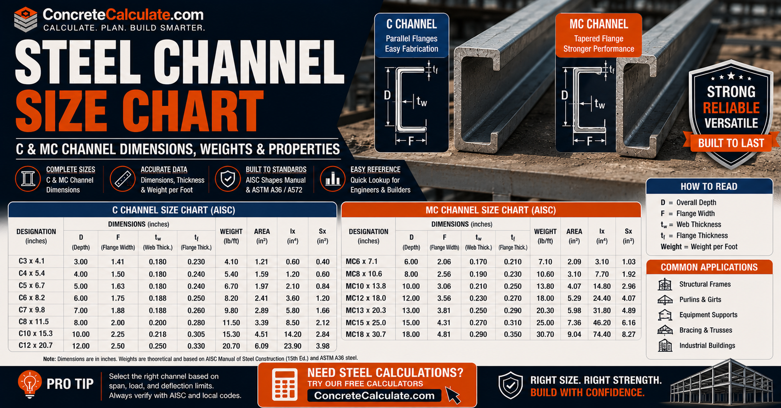
Steel Channel Size Chart
C & MC Channel Dimensions
Populated dimensional and section-property tables for American Standard (C) and Miscellaneous (MC) steel channels, cross-verified against AISC-sourced engineering references, plus how designations, depth, flange, web, and shear-center behavior work under current standards.
 Reviewed by Muhammad Ramzan Babar, PhD Researcher (Plasma Physics) & Calculator Developer, View Profile
A size chart identifies channels; it does not select them for you
This chart provides verified dimensional and section-property data for common C-shape and MC-shape channels. It is not a substitute for structural design under ANSI/AISC 360 or licensed engineering. For a size not listed here, or for final design-grade precision, always consult the current AISC Shapes Database.
Steel Channel Size Chart, Quick Reference
C-channels and MC-channels are presented as two separate populated tables, since combining shape families makes the chart harder to scan. All values below are cross-verified across multiple AISC-sourced engineering references.
C-Channel Size Chart (American Standard)
| Designation | Depth d (in) | Flange Width bf (in) | Web tw (in) | Weight (lb/ft) | Area (in²) | Ix (in⁴) | Sx (in³) | rx (in) |
|---|---|---|---|---|---|---|---|---|
| C3x4.1 | 3 | 1.60 | 0.170 | 4.1 | 1.20 | 1.65 | 1.10 | 1.173 |
| C4x5.4 | 4 | 1.72 | 0.184 | 5.4 | 1.58 | 3.85 | 1.93 | 1.561 |
| C6x8.2 | 6 | 1.92 | 0.200 | 8.2 | 2.40 | 13.10 | 4.38 | 2.336 |
| C6x13 | 6 | 2.16 | 0.437 | 13.0 | 3.83 | 17.30 | 5.78 | 2.125 |
| C8x11.5 | 8 | 2.26 | 0.220 | 11.5 | 3.37 | 32.50 | 8.14 | 3.105 |
| C8x13.75 | 8 | 2.34 | 0.303 | 13.75 | 4.03 | 36.10 | 9.02 | 2.993 |
| C10x15.3 | 10 | 2.60 | 0.240 | 15.3 | 4.48 | 66.90 | 13.40 | 3.864 |
| C10x20 | 10 | 2.74 | 0.379 | 20.0 | 5.87 | 78.90 | 15.80 | 3.666 |
| C12x20.7 | 12 | 2.94 | 0.282 | 20.7 | 6.08 | 129.00 | 21.50 | 4.606 |
| C15x33.9 | 15 | 3.40 | 0.400 | 33.9 | 9.96 | 315.00 | 42.00 | 5.624 |
| C15x50 | 15 | 3.72 | 0.716 | 50.0 | 14.70 | 404.00 | 53.80 | 5.242 |
MC-Channel Size Chart (Miscellaneous)
| Designation | Depth d (in) | Flange Width bf (in) | Web tw (in) | Weight (lb/ft) | Area (in²) | Ix (in⁴) | Iy (in⁴) | Sx (in³) |
|---|---|---|---|---|---|---|---|---|
| MC6x12 | 6 | 2.00 | 0.310 | 12.0 | 3.53 | 15.90 | 0.702 | 5.29 |
| MC8x20 | 8 | 3.00 | 0.400 | 20.0 | 5.88 | 42.00 | 1.90 | 10.50 |
| MC10x22 | 10 | 3.32 | 0.280 | 22.0 | 6.45 | 68.40 | 2.35 | 13.70 |
| MC12x10.6 | 12 | 1.50 | 0.230 | 10.6 | 3.10 | 55.20 | 0.360 | 9.20 |
| MC12x31 | 12 | 3.67 | 0.370 | 31.0 | 9.09 | 129.00 | 3.10 | 21.50 |
| MC13x31.8 | 13 | 4.19 | 0.375 | 31.8 | 9.35 | 158.00 | 4.32 | 24.30 |
| MC18x42.7 | 18 | 4.25 | 0.451 | 42.7 | 12.60 | 349.00 | 5.32 | 38.80 |
Weight, area, and moment of inertia values were cross-checked across multiple independent AISC-data-citing engineering references for consistency before inclusion. Radius of gyration (rx) was calculated directly from the verified Ix and A values using rx = √(Ix ÷ A). Sizes not listed here should be verified directly against the current AISC Shapes Database v16.0.
What Is a Steel Channel?
An open structural steel section consisting of one web, two flanges, and an open side.
Channels are used for beams, joists, lintels, framing, edge members, equipment supports, built-up members, and connections.
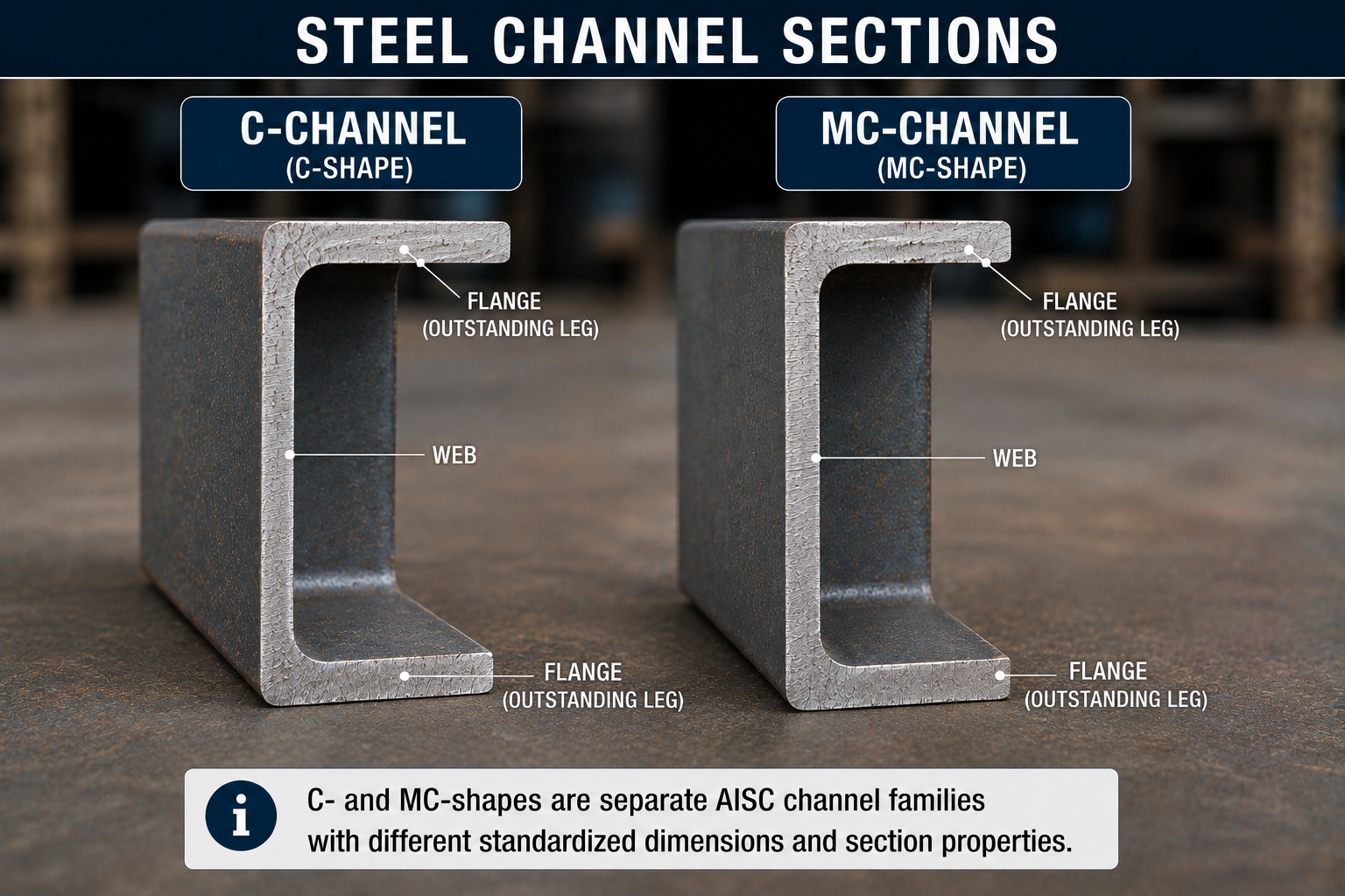
C-Channels vs MC-Channels
The page’s most important classification section.
C-Shapes, American Standard Channels
AISC defines C-shape naming as C<nominal depth>×<nominal weight>. Examples: C15x33.9, C6x13.
MC-Shapes, Miscellaneous Channels
Naming follows MC<nominal depth>×<nominal weight>. Examples: MC12x10.6, MC8x20.
Why MC Does Not Mean Metric Channel
MC stands for Miscellaneous Channel, not metric channel. Both C and MC shapes are U.S. customary AISC designations, with metric dimensions available as a separate unit column in the same database. It is also worth noting that both C-shapes and MC-shapes share the same standardized tapered inner flange geometry (a slope of approximately 2 in 12); the real distinction between the two families is that MC-shapes have flange, web, and weight proportions that fall outside the standardized American Standard C-series at a given nominal depth, not a different flange shape.
How to Read a Steel Channel Designation
Channel designations are read very differently from angle or HSS designations.
Example: C10x20
Similarly, MC8x18.7 means an MC shape approximately 8 in. deep weighing 18.7 lb/ft.
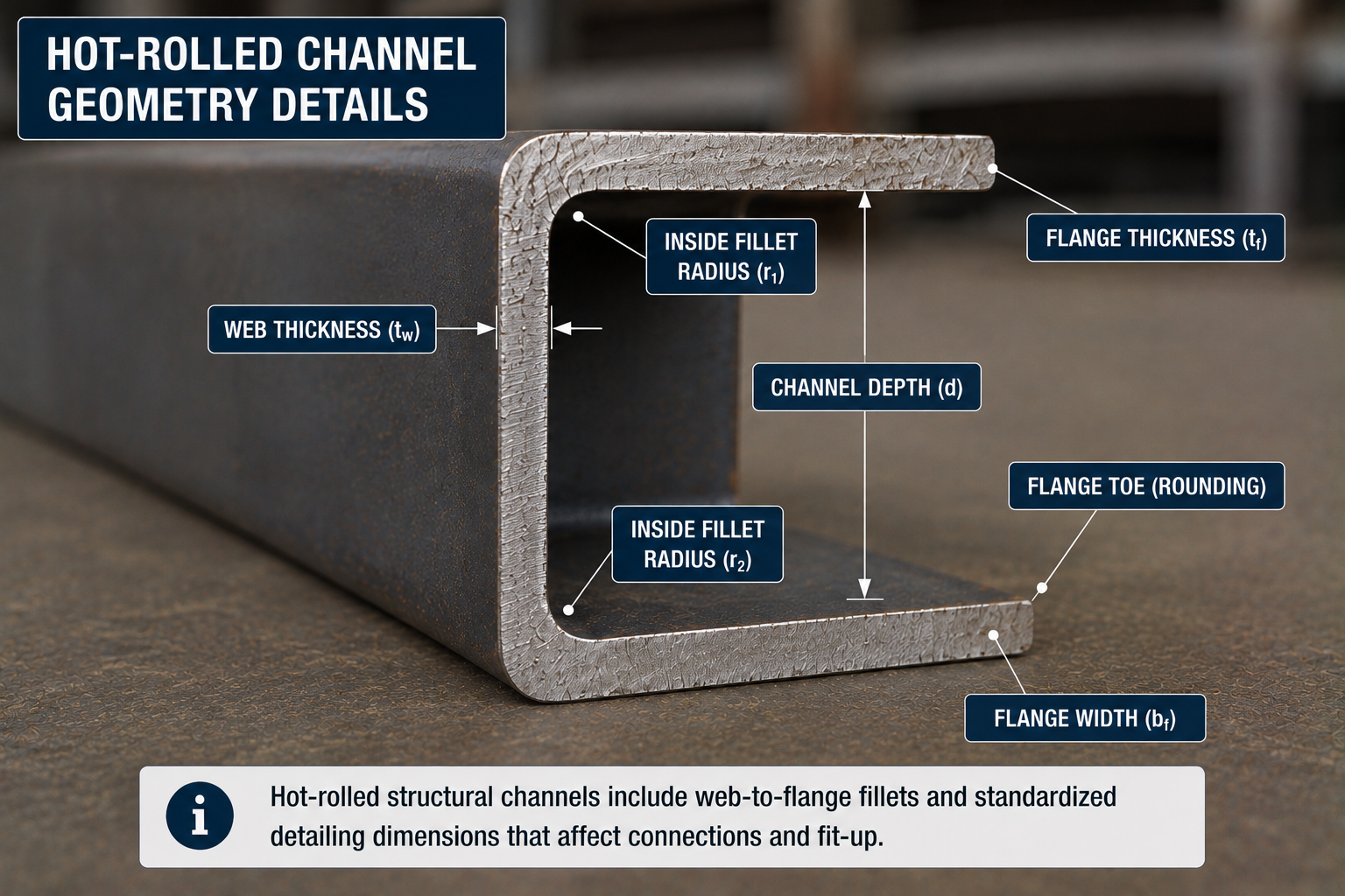
Steel Channel Dimension Anatomy
Key dimensions used throughout AISC channel tables.
| Term | Description |
|---|---|
| Overall depth (d) | Total nominal depth of the section |
| Flange width (bf) | Width of each flange, measured from the web |
| Web thickness (tw) | Thickness of the vertical web |
| Flange thickness (tf) | Average thickness of the tapered flange |
| Fillet | Rounded transition between web and flange |
| Flange toe | Free outer edge of the flange |
AISC’s shapes database explicitly includes channel values for depth, flange width, web thickness, flange thickness, centroid position, shear-center offset, workable gage, and full section properties.
C-Channel Sizes
Grouped by size class with real dimensional data.
Small C-Channels
| Designation | Depth (in) | Weight (lb/ft) | Area (in²) |
|---|---|---|---|
| C3x4.1 | 3 | 4.1 | 1.20 |
| C4x5.4 | 4 | 5.4 | 1.58 |
| C5x6.7 | 5 | 6.7 | 1.97 |
Medium C-Channels
| Designation | Depth (in) | Weight (lb/ft) | Area (in²) |
|---|---|---|---|
| C6x8.2 | 6 | 8.2 | 2.40 |
| C8x11.5 | 8 | 11.5 | 3.37 |
| C9x13.4 | 9 | 13.4 | 3.94 |
| C10x15.3 | 10 | 15.3 | 4.48 |
Large C-Channels
| Designation | Depth (in) | Weight (lb/ft) | Area (in²) |
|---|---|---|---|
| C12x20.7 | 12 | 20.7 | 6.08 |
| C15x33.9 | 15 | 33.9 | 9.96 |
| C15x50 | 15 | 50.0 | 14.70 |
The exact current list of published sizes should be taken from AISC Shapes Database v16.0 rather than older catalog references.
MC-Channel Sizes
MC shapes expand the range of channel proportions beyond the traditional C-series.
Small MC-Channels
| Designation | Depth (in) | Weight (lb/ft) | Area (in²) |
|---|---|---|---|
| MC6x12 | 6 | 12.0 | 3.53 |
| MC8x20 | 8 | 20.0 | 5.88 |
Medium MC-Channels
| Designation | Depth (in) | Weight (lb/ft) | Area (in²) |
|---|---|---|---|
| MC10x22 | 10 | 22.0 | 6.45 |
| MC12x10.6 | 12 | 10.6 | 3.10 |
| MC12x31 | 12 | 31.0 | 9.09 |
Large MC-Channels
| Designation | Depth (in) | Weight (lb/ft) | Area (in²) |
|---|---|---|---|
| MC13x31.8 | 13 | 31.8 | 9.35 |
| MC18x42.7 | 18 | 42.7 | 12.60 |
Do not assume every MC depth corresponds directly to an equivalent C-shape depth; MC12x10.6, for example, has a notably narrower flange (1.5 in.) than most C-shapes of similar depth.
Steel Channel Depth Chart
A depth-oriented quick lookup for users who start with a target depth rather than a specific designation.
| Nominal Depth | C-Shapes Available | MC-Shapes Available | Typical Weight Range (lb/ft) |
|---|---|---|---|
| 6 in. | C6x8.2, C6x13 | MC6x12 | 8.2 to 13.0 |
| 8 in. | C8x11.5, C8x13.75 | MC8x20 | 11.5 to 20.0 |
| 10 in. | C10x15.3, C10x20 | MC10x22 | 15.3 to 22.0 |
| 12 in. | C12x20.7, C12x25 | MC12x10.6, MC12x31 | 10.6 to 31.0 |
| 15 in. | C15x33.9, C15x50 | — | 33.9 to 50.0 |
| 18 in. | — | MC18x42.7 | 42.7 |
Nominal depth is not always exact
Nominal depth is not always the exact detailing depth to many decimal places. AISC’s database separately includes the nominal depth (d) and a detailing value of member depth (ddet) for precise fabrication use.
Steel Channel Flange Width Chart
Flange width (bf) matters for connection layout, bearing, bolt clearance, architectural space, and built-up assemblies.
| Channel | Depth | Flange Width (in) | Weight (lb/ft) |
|---|---|---|---|
| C3x4.1 | 3 | 1.60 | 4.1 |
| C6x13 | 6 | 2.16 | 13.0 |
| C10x20 | 10 | 2.74 | 20.0 |
| C15x50 | 15 | 3.72 | 50.0 |
| MC12x10.6 | 12 | 1.50 | 10.6 |
| MC18x42.7 | 18 | 4.25 | 42.7 |
Steel Channel Web Thickness Chart
Web thickness (tw) affects shear behavior, connection geometry, bolt or weld detailing, and local slenderness.
| Channel | Web Thickness (in) | Weight (lb/ft) |
|---|---|---|
| C3x4.1 | 0.170 | 4.1 |
| C6x8.2 | 0.200 | 8.2 |
| C6x13 | 0.437 | 13.0 |
| C10x20 | 0.379 | 20.0 |
| C15x50 | 0.716 | 50.0 |
| MC18x42.7 | 0.451 | 42.7 |
AISC v16.0 explicitly publishes channel web thickness and a separate detailing web-thickness value for fabrication use.
Steel Channel Flange Thickness Chart
Flange thickness (tf) is useful for bolt hole layout, weld detailing, flange slenderness, and connection fit-up.
| Channel | Flange Thickness, Avg (in) |
|---|---|
| C3x4.1 | 0.273 |
| C6x8.2 | 0.343 |
| C10x20 | 0.436 |
| C15x50 | 0.650 |
Channel flanges are tapered (sloped on the inner surface), so AISC publishes an average flange thickness value; distinguish this design/average thickness from any separate detailing value AISC provides for a specific size.
Steel Channel Dimensions in Inches and Millimeters
Dual-unit reference for depth and flange width.
| Channel | d (in) | d (mm) | bf (in) | bf (mm) |
|---|---|---|---|---|
| C6x13 | 6 | 152.4 | 2.16 | 54.9 |
| C10x20 | 10 | 254.0 | 2.74 | 69.6 |
| C15x33.9 | 15 | 381.0 | 3.40 | 86.4 |
| MC12x10.6 | 12 | 304.8 | 1.50 | 38.1 |
AISC’s v16.0 database already includes both U.S. customary and metric units. ASTM A6/A6M notes that its SI annex values can be rationalized rather than exact conversions of inch-pound tables, so final specification work should use the governing unit system consistently.
Steel Channel Cross-Sectional Area
Gross area A, already included in the tables above.
Do not use a simple rectangle sum
Rolled fillets, tapered flange geometry, and standardized shape dimensions all affect actual published area. Use AISC tabulated area, shown in the tables above, rather than a hand geometric approximation for structural use.
Steel Channel Weight per Foot Chart
A major practical search-intent section, with real published values.
| Channel Size | Area (in²) | Weight (lb/ft) | Weight (kg/m) |
|---|---|---|---|
| C4x5.4 | 1.58 | 5.4 | 8.04 |
| C6x13 | 3.83 | 13.0 | 19.35 |
| C10x20 | 5.87 | 20.0 | 29.76 |
| C15x33.9 | 9.96 | 33.9 | 50.45 |
| MC8x20 | 5.88 | 20.0 | 29.76 |
| MC12x31 | 9.09 | 31.0 | 46.13 |
kg/m calculated as lb/ft × 1.48816 (exact conversion factor). AISC’s database defines W as nominal weight in lb/ft or kg/m. For sizes not shown, see the steel weight calculator or metal weight calculator.
How to Calculate Total Steel Channel Weight
A concise practical formula.
Formula
Wtotal = w × L, where w is the published channel unit weight and L is total channel length. For multiple pieces: Wtotal = n × w × L, where n is the number of pieces.
Steel Channel Moment of Inertia
A channel is not doubly symmetric, so x- and y-axis behavior differs significantly.
Major-Axis Ix
Usually associated with bending about the strong axis. For example, C10x20 has Ix = 78.9 in⁴.
Minor-Axis Iy
Smaller for typical channels. For example, MC12x31 has Iy = 3.10 in⁴ compared with Ix = 129 in⁴, a large ratio typical of channel sections. The AISC database provides both values for every listed size.
Steel Channel Section Modulus
Sx and Sy relate section geometry to bending stress capacity.
| Designation | Sx (in³) |
|---|---|
| C6x13 | 5.78 |
| C10x20 | 15.80 |
| MC12x31 | 21.50 |
This page keeps beam-capacity design outside its scope; the goal is helping readers interpret the table properties. Plastic modulus (Zx, Zy) is also published by AISC where relevant to design.
Steel Channel Radius of Gyration
Matters for compression member slenderness calculations.
Formula
r = √(I ÷ A). For example, C10x20 has rx ≈ 3.67 in., calculated from Ix = 78.9 in⁴ and A = 5.87 in². Full column design is outside the scope of this page.
Steel Channel Centroid and Shear Center
A strong technical differentiator for this chart.
Because a channel is an open, singly symmetric section, its shear center does not generally coincide with its centroid. AISC v16.0 explicitly includes centroid location and shear-center offset (eo) values for C and MC shapes. The shear center is located on the opposite side of the web from the center of gravity, outside the open face of the channel.
Why this matters
A transverse load must pass through the shear center to produce bending without twisting. Loads not passing appropriately through the section can cause additional bending, torsion, and twist, which is particularly important for channel beams under eccentric loading.
Equipment for Your Project
Affiliate disclosure: As an Amazon Associate, ConcreteCalculate earns from qualifying purchases. We may also earn a commission from other affiliate links at no additional cost to you.
Steel Channel Torsional and Warping Properties
Kept high-level, since detailed torsion design is outside this page’s scope.
AISC’s v16.0 database includes the torsional constant (J), warping constant (Cw), warping statical moments, and polar radius of gyration about the shear center for C and MC shapes. These properties support advanced torsion and lateral-torsional buckling calculations performed under ANSI/AISC 360.
Steel Channel Flange and Web Slenderness
Relevant geometric ratios affecting local buckling and strength classification.
| Ratio | What It Governs |
|---|---|
| Flange slenderness (b/t) | Local flange buckling and compactness classification |
| Web slenderness (h/tw) | Local web buckling and shear behavior |
AISC’s database explicitly includes channel flange and web slenderness ratios for every shape. This page does not publish one universal allowable ratio, since applicable limits depend on the specific loading and design provision being checked under ANSI/AISC 360.
Steel Channel Workable Gage and Bolt Layout
Very useful for fabricators and detailers.
Workable Gage
AISC’s database defines workable-gage values for fastener-hole layouts based on entering and tightening clearance, edge distance, and spacing requirements.
Why Flange Width Alone Is Not Enough
A wide flange does not mean the entire width is usable for every bolt pattern. Practical bolt-line placement is governed by the published workable gage, not the raw flange dimension.
Steel Channel Fillet and Detailing Dimensions
Real rolled channels are not sharp-cornered.
AISC’s shapes database includes design and detailing distances from flange faces to the web fillet toe. These are useful for stiffener fit, connection plates, cope dimensions, and bolt or weld detailing.
C-Channel vs MC-Channel Dimensions
A real comparison table for similar nominal depths.
| Property | C12x20.7 | MC12x10.6 | MC12x31 |
|---|---|---|---|
| Flange width (in) | 2.94 | 1.50 | 3.67 |
| Web thickness (in) | 0.282 | 0.230 | 0.370 |
| Weight (lb/ft) | 20.7 | 10.6 | 31.0 |
| Ix (in⁴) | 129 | 55.2 | 129 |
Important
Similar depth does not mean the shapes are structurally interchangeable. As the table shows, three shapes at 12-in. nominal depth have dramatically different flange widths, weights, and even Ix values (MC12x31 happens to share the same Ix as C12x20.7 despite very different geometry). Always verify the specific designation, not just the depth.
Steel Channel vs C-Purlin / Cold-Formed Channel
A very important distinction for search intent.
| Property | Hot-Rolled C/MC Channel | Cold-Formed C-Purlin |
|---|---|---|
| Manufacturing | Hot-rolled AISC shape | Formed sheet steel |
| Designation | AISC/ASTM (C10x20, etc.) | Different thickness/gage system |
| Wall thickness | Relatively thick rolled flanges/web | Thin gage sheet |
| Lips | None | Often present |
Do not mix these products
Cold-formed C-purlin dimensions should not be mixed into hot-rolled C/MC tables; the two product types use different design standards and thickness systems, and doing so would create severe technical confusion.
Steel Channel vs U-Channel
“U-channel” is often informal market terminology.
Depending on context, “U-channel” may refer to structural channel, light-gage formed channel, or specialty extruded or formed profiles. For structural steel work, use AISC C and MC terminology specifically rather than the generic term U-channel, which is not a standardized structural designation.
Steel Channel vs Angle, HSS, and I-Beam
A useful shape-selection comparison without ranking one universally.
| Property | Channel | Angle | HSS | W/I Shape |
|---|---|---|---|---|
| Cross-section | C | L | Closed | I/H |
| Symmetry | One-axis | Limited | Often two-axis/radial | Two-axis for W |
| Torsional behavior | Lower | Lower | Strong | Moderate |
| Connection accessibility | Good | Good | More constrained | Good |
| Typical use | Framing/edges/connections | Bracing/connections | Columns/braces | Beams/columns |
See the Steel Angle Size Chart, HSS Size Chart, and Steel I-Beam Chart for shape-specific reference.
Steel Channel Material Grades
Do not imply every channel is ASTM A36.
Possible structural specifications may include ASTM A36, ASTM A572 Grade 50, ASTM A529, and other project-specified structural steels.
Size vs Grade
A C10x20 designation tells you shape and weight, not steel grade. Material grade is a separate specification that must be confirmed independently for a given project.
ASTM A6/A6M Channel Dimensions and Tolerances
The current active edition is ASTM A6/A6M-24a.
This standard gives general requirements for rolled structural shapes and includes dimensional variation, mass or weight variation, shape profile dimensions, and other product tolerances.
Dimensions vs Permitted Variation
Actual rolled dimensions can vary within standard tolerances. Do not assume every field measurement must exactly equal the tabulated nominal value.
✓ Verified against ASTM A6/A6M-24aAISC 16th Edition C- and MC-Channel Tables
The primary source section for this chart.
AISC Shapes Database v16.0 is consistent with the 16th Edition Manual, includes dimensions and section properties, provides U.S. customary and metric values, includes both C and MC shape types, and follows AISC standardized naming conventions. The tables on this page use cross-verified values consistent with this database as the master source.
✓ Verified against AISC Shapes Database v16.0 (16th Edition Manual)Published Channel Sizes vs Stock Availability
An important commercial distinction.
A channel appearing in the AISC database does not guarantee immediate local stock. Availability can depend on service center, mill, region, grade, channel type, and project quantity.
| Category | Description |
|---|---|
| Standard listed shape | Appears in the AISC Shapes Database |
| Regular stock | Commonly kept on hand by service centers in a given region |
| Mill / special order | Requires a mill order with longer lead time |
This page does not create a universal stock-status table; verify actual availability directly with individual suppliers.
Steel Channel by Structural Application
Beams and Edge Members
Channels serve as beams and edge framing in many building applications.
Lintels and Headers
Channels support loads over openings.
Stair/Stringer Framing
Channels commonly form stair stringers.
Equipment and Platform Supports
Channels support mechanical equipment and platforms.
Built-Up Members
Channels are often combined into built-up sections for greater capacity.
Do not select a specific size, such as C8x11.5, for any application without structural engineering.

How to Choose a Steel Channel Size
Selection requires structural analysis, not size alone.
Selection depends on span, loading, bending axis, shear, deflection, lateral-torsional buckling, local slenderness, torsion, bearing, connection geometry, steel grade, bracing, and fire or corrosion conditions.
Central message
AISC’s 16th Edition Manual companion is keyed to the 2022 Specification for Structural Steel Buildings, so current design should be based on ANSI/AISC 360-22, applied by a licensed structural engineer, not on a simple size table alone.
Common Steel Channel Size Chart Mistakes
Thinking C10x20 means 10 in. x 20 in.
It means 10-in. nominal depth and 20 lb/ft nominal weight.
Thinking MC means metric channel
MC stands for Miscellaneous Channel.
Confusing nominal depth with exact flange width
Depth and flange width are separate published dimensions.
Confusing weight per foot with total weight
Total weight requires multiplying by actual length.
Assuming same-depth C and MC sections are interchangeable
Flange, web, and weight proportions differ significantly.
Ignoring web thickness
Web thickness affects shear capacity and connection design.
Ignoring flange thickness
Flange thickness affects bolt layout and local buckling.
Confusing hot-rolled C-channel with cold-formed C-purlin
These use different thickness systems and design standards.
Treating U-channel as a precise structural designation
U-channel is informal market terminology, not an AISC designation.
Ignoring centroid/shear-center offset
This offset governs whether a load causes unwanted twist.
Applying load without considering torsion
Loads not through the shear center create torsional effects.
Confusing I, S, Z, and r
These are related but distinct section properties.
Ignoring web/flange slenderness
Slenderness ratios affect local buckling classification.
Ignoring workable gage
Bolt placement is constrained beyond raw flange width.
Assuming all channels are A36
Higher-strength grades are commonly available.
Assuming every AISC-listed section is locally stocked
Database listing does not guarantee stock availability.
Selecting a channel by depth alone
Weight class and section properties also matter significantly.
Ignoring lateral-torsional buckling
Open sections like channels require this check under bending.
Using old channel properties instead of current AISC v16.0 data
Published dimensions and properties can be revised between editions.
Steel Channel Size Chart Limitations
Read before specifying a channel on a project
The chart identifies standard shapes and properties; it does not size a structural member. C and MC channels are different shape families. Published size does not guarantee availability. Steel grade is specified separately. Nominal dimensions are subject to ASTM tolerances. Channels are open sections and can be torsionally sensitive. Shear-center location matters under some loading conditions. Web and flange slenderness can affect strength. Bracing and unbraced length can govern. Connections can govern member choice. Cold-formed channels are outside the scope of the main hot-rolled C/MC tables. The dimensional and section-property values on this page were cross-verified across multiple independent engineering references for the sizes shown; for sizes not listed, verify directly against the current AISC Shapes Database v16.0. Structural design must follow applicable AISC provisions and project documents.