Drill Bit Size Chart – Fractional, Number, Letter & Metric
Drill Bit Size Chart
Fractional, Number, Letter & Metric
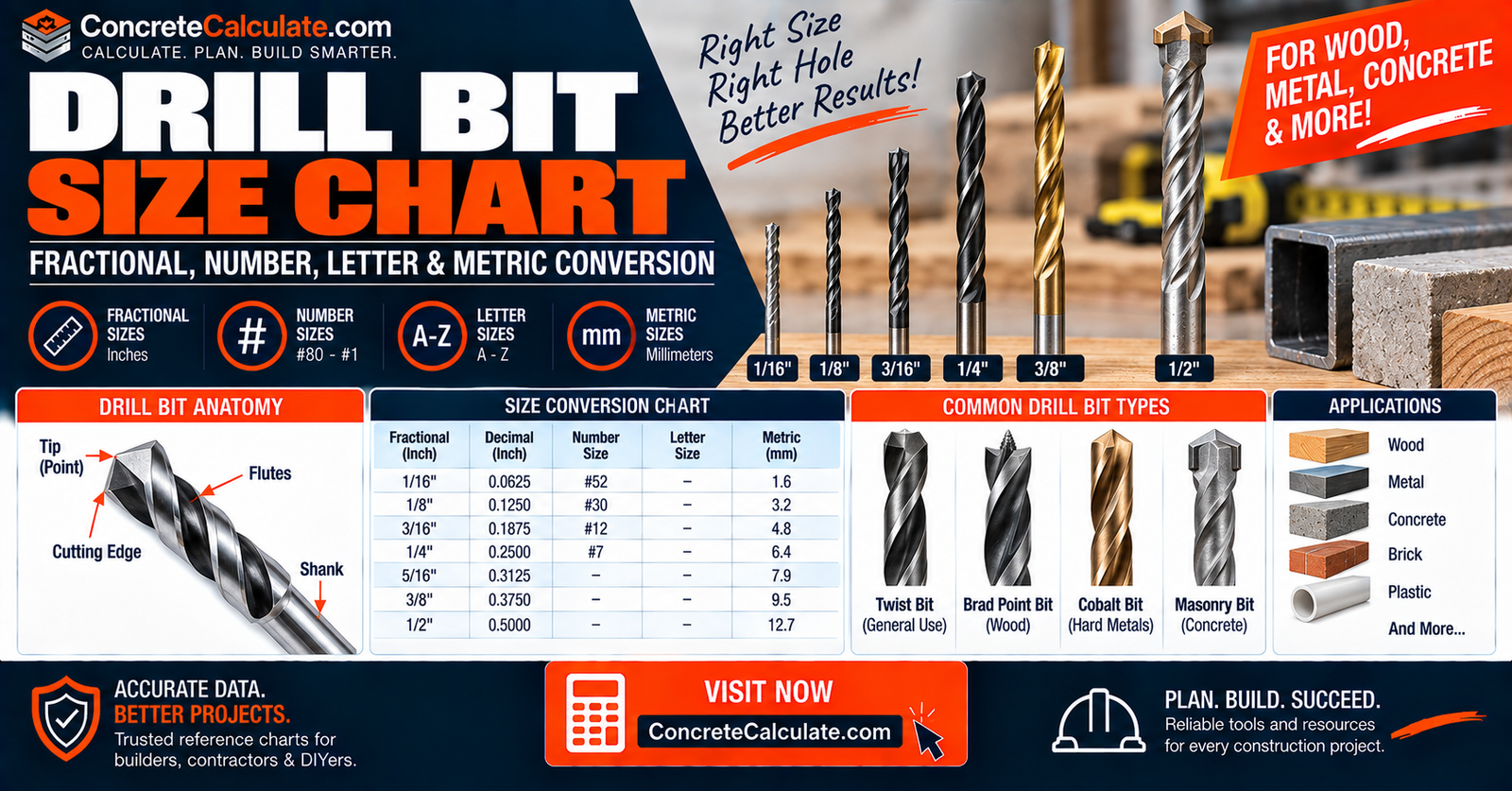
Fractional-inch, number (#80 to #1), letter (A to Z), decimal-inch, and metric drill sizes in one conversion chart, plus how to choose the right bit for the job.
 Reviewed by Muhammad Ramzan Babar, PhD Researcher (Plasma Physics) & Calculator Developer, View Profile
Drill bit size identifies diameter, not hole purpose
This chart helps you identify and convert between fractional, number, letter, and metric drill sizes. It is not a substitute for the Tap Drill Chart (thread tapping), Pilot Hole Size Chart (screws), or Clearance Hole Size Chart (pass-through fasteners), which each apply a specific purpose on top of the raw diameter shown here.
Drill Bit Size Chart, Quick Reference
A compact conversion table combining all four main U.S. drill sizing systems.
Unified Drill Bit Size Conversion Chart
| Drill Size | System | Decimal Inch | Millimeters | Nearest Fraction |
|---|---|---|---|---|
| 1/16 | Fractional | 0.0625 | 1.588 | 1/16 |
| #30 | Number | 0.1285 | 3.264 | 1/8 |
| 1/8 | Fractional | 0.1250 | 3.175 | 1/8 |
| #7 | Number | 0.2010 | 5.105 | 13/64 |
| 1/4 | Fractional | 0.2500 | 6.350 | 1/4 |
| F | Letter | 0.2570 | 6.528 | 1/4 |
| Q | Letter | 0.3320 | 8.433 | 21/64 |
| 3/8 | Fractional | 0.3750 | 9.525 | 3/8 |
| 1/2 | Fractional | 0.5000 | 12.700 | 1/2 |
Main U.S. Drill Size Systems
| System | Range | Common Use |
|---|---|---|
| Fractional | 1/64 to 1 in and beyond | Common construction and shop sizes |
| Number | #80 (smallest) to #1 (largest) | Precision, tapping, small-diameter work |
| Letter | A (smallest) to Z (largest) | Fills gap above number drills |
| Metric | Millimeter diameter | Metric hardware, imported tooling |
What Is Drill Bit Size?
The nominal cutting diameter of the bit, expressed in one of several labeling systems.
Typical labeling systems include fraction of an inch, decimal inch, number, letter, and millimeters. A bit labeled “#7” is a number drill, not a 7 mm bit. Likewise, a “G” drill is a letter size, not a gauge number. Confusing these systems is one of the most common mistakes in bit selection.
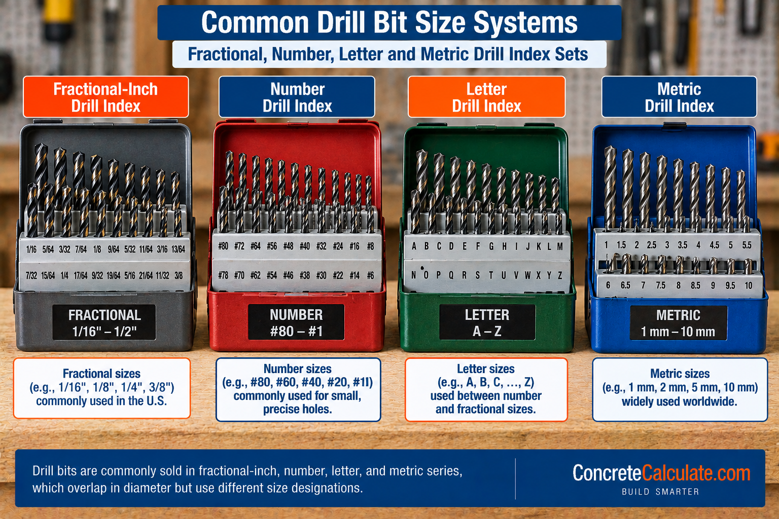
The Four Main Drill Bit Size Systems
An orientation before the detailed tables.
| System | Example Sizes |
|---|---|
| Fractional Inch | 1/16, 1/8, 1/4, 3/8, 1/2 |
| Number Drills | #80 through #1 |
| Letter Drills | A through Z |
| Metric | 2.0 mm, 3.0 mm, 5.0 mm, 6.5 mm, 10.0 mm |
These systems overlap in diameter but often do not have exact equivalents; a metric bit and a fractional bit of similar size may differ by a few thousandths of an inch.
Fractional Drill Bit Size Chart
The everyday U.S. shop and construction sizing series.
| Fraction | Decimal Inch | Millimeters |
|---|---|---|
| 1/64 | 0.0156 | 0.397 |
| 1/32 | 0.0313 | 0.794 |
| 1/16 | 0.0625 | 1.588 |
| 3/32 | 0.0938 | 2.381 |
| 1/8 | 0.1250 | 3.175 |
| 3/16 | 0.1875 | 4.763 |
| 1/4 | 0.2500 | 6.350 |
| 5/16 | 0.3125 | 7.938 |
| 3/8 | 0.3750 | 9.525 |
| 7/16 | 0.4375 | 11.113 |
| 1/2 | 0.5000 | 12.700 |
Number Drill Bit Size Chart (#80 to #1)
A full standalone reference for the number drill series.
| Number | Decimal Inch | Millimeters | Nearest Fraction |
|---|---|---|---|
| #80 | 0.0135 | 0.343 | 1/64 |
| #60 | 0.0400 | 1.016 | 1/32 |
| #50 | 0.0700 | 1.778 | 5/64 |
| #40 | 0.0980 | 2.489 | 3/32 |
| #35 | 0.1100 | 2.794 | 7/64 |
| #30 | 0.1285 | 3.264 | 1/8 |
| #29 | 0.1360 | 3.454 | 9/64 |
| #20 | 0.1610 | 4.089 | 5/32 |
| #10 | 0.1935 | 4.915 | 3/16 |
| #7 | 0.2010 | 5.105 | 13/64 |
| #1 | 0.2280 | 5.791 | 15/64 |
Important
Number values run opposite to diameter: #80 is much smaller than #1. Higher number does not mean bigger bit in this series.
Letter Drill Bit Size Chart (A to Z)
Fills the size gap immediately above the number drill series.
| Letter | Decimal Inch | Millimeters | Nearest Fraction |
|---|---|---|---|
| A | 0.2340 | 5.944 | 15/64 |
| D | 0.2460 | 6.248 | 1/4 |
| E | 0.2500 | 6.350 | 1/4 |
| F | 0.2570 | 6.528 | 1/4 |
| H | 0.2660 | 6.756 | 17/64 |
| M | 0.2950 | 7.493 | 19/64 |
| Q | 0.3320 | 8.433 | 21/64 |
| U | 0.3680 | 9.347 | 23/64 |
| Z | 0.4130 | 10.490 | 13/32 |
Metric Drill Bit Size Chart
Common metric drill sizes and their inch equivalents.
| Metric Size (mm) | Decimal Inch | Nearest Fraction |
|---|---|---|
| 1.0 | 0.0394 | 1/32 |
| 2.0 | 0.0787 | 5/64 |
| 3.0 | 0.1181 | 1/8 |
| 4.0 | 0.1575 | 5/32 |
| 5.0 | 0.1969 | 13/64 |
| 6.0 | 0.2362 | 15/64 |
| 6.5 | 0.2559 | 1/4 |
| 8.0 | 0.3150 | 5/16 |
| 10.0 | 0.3937 | 25/64 |
Do not assume every manufacturer stocks every 0.1 mm increment; available sizes vary by brand and drill set.
Fractional to Decimal Drill Size Chart
One of the most useful quick-conversion sections on this page.
| Fraction | Decimal |
|---|---|
| 1/64 | 0.015625 |
| 1/32 | 0.03125 |
| 3/64 | 0.046875 |
| 1/16 | 0.0625 |
| 5/64 | 0.078125 |
| 3/32 | 0.09375 |
| 7/64 | 0.109375 |
| 1/8 | 0.125 |
| 5/32 | 0.15625 |
| 3/16 | 0.1875 |
| 1/4 | 0.250 |
| 3/8 | 0.375 |
| 1/2 | 0.500 |
Fractional Drill Size to Millimeter Chart
Serves DIYers who own mixed SAE and metric bit sets.
| Fraction | Decimal Inch | mm |
|---|---|---|
| 1/16 | 0.0625 | 1.588 |
| 1/8 | 0.1250 | 3.175 |
| 3/16 | 0.1875 | 4.763 |
| 1/4 | 0.2500 | 6.350 |
| 5/16 | 0.3125 | 7.938 |
| 3/8 | 0.3750 | 9.525 |
| 1/2 | 0.5000 | 12.700 |
Conversion: 1 in = 25.4 mm exactly.
Metric to Inch Drill Bit Conversion Chart
A reverse lookup, distinct in direction from the previous section.
| mm | Decimal Inch | Nearest Fraction |
|---|---|---|
| 3 | 0.1181 | 1/8 |
| 5 | 0.1969 | 13/64 |
| 6 | 0.2362 | 15/64 |
| 8 | 0.3150 | 5/16 |
| 10 | 0.3937 | 25/64 |
| 12 | 0.4724 | 15/32 |
Unified Number, Letter, Fractional, and Metric Drill Chart
The strongest single conversion asset on this page, sorted by increasing decimal diameter.
| Decimal Inch | Fraction | Number | Letter | Metric Approx. |
|---|---|---|---|---|
| 0.0135 | – | #80 | – | 0.34 mm |
| 0.1250 | 1/8 | – | – | 3.18 mm |
| 0.1285 | – | #30 | – | 3.26 mm |
| 0.2010 | – | #7 | – | 5.11 mm |
| 0.2280 | – | #1 | – | 5.79 mm |
| 0.2340 | – | – | A | 5.94 mm |
| 0.2500 | 1/4 | – | E | 6.35 mm |
| 0.2570 | – | – | F | 6.53 mm |
| 0.3320 | – | – | Q | 8.43 mm |
| 0.3750 | 3/8 | – | – | 9.53 mm |
| 0.4130 | – | – | Z | 10.49 mm |
Important
Metric approximations are labeled as nearest equivalent, not exact matches, since fractional, number, letter, and metric systems rarely align perfectly.
How Number Drill Sizes Work
Not a linear or intuitive increment system.
Number drills range from #80 to #1. #80 is the smallest size, and #1 is the largest, filling gaps between common fractions. This system is particularly useful for tapping, precision drilling, machining, and clearance holes where a fractional size alone would leave too large a gap.
How Letter Drill Sizes Work
A companion system to the number series, useful above the numbered range.
Letter drills run from A, the smallest, through Z, the largest. The current chart spans A at 0.234 in through Z at 0.413 in, picking up in diameter immediately above the largest number drill, #1 at 0.228 in.
ASME B94.11M Twist Drill Standard
The authority section behind every dimension on this page.
ASME B94.11M-1993 remains in effect under stabilized maintenance and covers twist drill nomenclature, definitions, sizes, and tolerances for high-speed-steel drills, straight and taper shanks, inch and metric sizes, and combined drills and countersinks. The standard defines drill dimensions and tolerances; it does not tell you what hole size every screw, bolt, or tap requires, which is why this page links out to the specific-purpose hole charts throughout.
✓ Verified Against ASME B94.11M-1993Drill Bit Size vs Actual Hole Size
A very important technical distinction that raises this chart’s practical value.
A nominal 1/4-in drill does not necessarily produce an exactly 0.2500-in finished hole in every condition. Actual hole size can be affected by drill runout, drill wear, machine or tool rigidity, workpiece material, point geometry, feed rate, and spindle or hand-drill alignment. Drill diameter and finished-hole tolerance are related but not identical concepts.
Drill Bit Tolerance and Hole Accuracy
For close-tolerance work, drilling is often just the first step.
For close-tolerance work, drilling may be followed by reaming, boring, or honing to achieve final required dimensions. Do not assume a twist drill alone produces a precision-fit hole automatically. ASME B94.11M establishes drill dimensional tolerances, but achieving a tighter finished-hole tolerance typically requires an additional finishing operation.
Drill Bit Size vs Pilot Hole Size
A critical cannibalization boundary for this chart cluster.
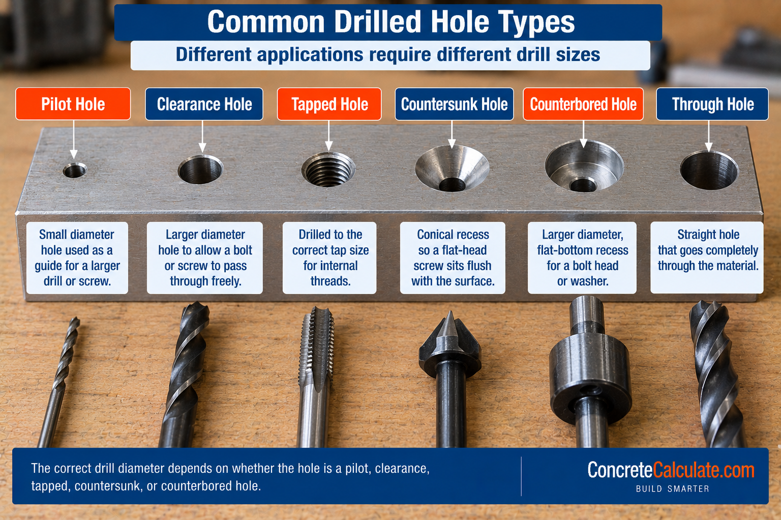
This Drill Bit Size Chart answers “what diameter is this drill?” The Pilot Hole Size Chart answers “what hole should I drill before driving this screw?” These are related but distinct questions; pilot hole diameter depends on screw type, thread, and wood species, not simply the closest drill to the screw’s outside diameter.
Drill Bit Size vs Tap Drill Size
Another major boundary between this chart and a specialized reference.
Tap drill size depends on the thread’s major diameter, pitch or threads per inch, and desired thread engagement percentage. Common examples include #6-32 requiring a #35 drill, 1/4-20 requiring a #7 drill, and 3/8-24 requiring a Q drill. The complete size-by-thread reference belongs to the Tap Drill Chart; this page explains the conceptual relationship and links out rather than duplicating that dataset.
Drill Bit Size vs Clearance Hole Size
A clearance hole is intentionally larger than the bolt or screw body.
A 1/4-in bolt does not necessarily use a 1/4-in clearance drill. The appropriate drill depends on fastener size, whether a close, normal, or loose fit is required, and the applicable standard. See the Clearance Hole Size Chart for the complete fit-class reference.
Drill Bit Size vs Structural Bolt Hole Size
General machining clearance is a different question from structural bolt hole category.
Structural bolted connections use standardized hole categories, including standard, oversize, and slotted holes, governed by structural steel standards. The Bolt Hole Size Chart owns this structural-specific reference; this master drill chart simply explains that drilling-tool diameter and allowable structural hole category are separate questions requiring separate references.
Drill Bit Size vs Countersink and Counterbore Size
Two related but distinct secondary machining operations.
A countersink uses a hole diameter, a conical recess diameter, and an included angle. A counterbore requires a base or clearance hole plus a larger cylindrical recess and a specified depth. See the Countersink Size Chart and Counterbore Size Chart for the complete angle and dimension tables rather than duplicating them here.
Drill Bit Sizes for Screws and Wood Screws
A broad, practical overview.
The correct drill depends on whether you need a pilot hole, a clearance hole, a tapped hole, or a countersink. Do not assume you should use a drill bit the same size as the screw; that is often wrong and can split wood or strip threads. Key inputs for wood screws include screw major diameter, root or minor diameter, hardwood versus softwood, threaded versus unthreaded shank, and required clearance. See the Wood Screw Size Chart and Pilot Hole Size Chart for the complete screw-specific reference.
Drill Bit Sizes for Lag Screws
Lag fasteners may need multiple different hole diameters along their length.
Lag fasteners may need a lead or pilot hole for the threaded portion, a clearance hole through the attached member, and possibly a larger clearance hole under the unthreaded shank. Exact pilot sizes depend on material and fastener requirements; see the Lag Bolt Sizes Chart for lag-specific sizing.
Drill Bit Sizes for Concrete Anchors
Important construction relevance, with a strong safety caveat.
Masonry and concrete anchors often require a hole diameter specified directly by the anchor manufacturer. Anchor categories include concrete screws, wedge anchors, sleeve anchors, and drop-in anchors, each with their own required drill diameter.
Important
Do not determine anchor drill size from anchor diameter by guesswork. Follow the anchor listing and manufacturer instructions exactly.
Drill Bit Sizes for Metal
Focused on diameter selection, not cutting speeds or techniques.
Consider the exact target hole diameter, whether a tap or clearance requirement applies, deburring needs, reaming allowance if precision matters, and whether the work is thin sheet or thick plate. This chart addresses diameter selection only; cutting speeds, feeds, and coolant practices are outside its scope.
Drill Bit Sizes for Wood
Wood drilling involves multiple bit geometries at the same nominal diameter.
Wood drilling can involve twist bits, brad-point bits, augers, spade bits, and Forstner bits. Their labeled diameter can be the same while geometry and application differ substantially; keep size selection separate from bit-type selection when planning a project.
Twist, Brad-Point, Spade, Forstner, and Masonry Bit Sizes
A beginner-friendly comparison across bit geometries.
| Drill Type | Diameter Label Basis | Best For |
|---|---|---|
| Twist | Cutting diameter | Metal, general drilling |
| Brad Point | Cutting diameter | Wood, precise starting point |
| Spade | Cutting diameter | Larger wood holes |
| Forstner | Cutting diameter | Flat-bottom, clean wood holes |
| Masonry | Nominal cutting diameter | Concrete, brick, masonry |
Drill Bit Shank Size vs Cutting Diameter
A genuinely useful practical distinction for tool selection.
The shank can differ from the nominal cutting diameter. Examples include reduced-shank bits, Silver and Deming-type larger bits, and hex-shank bits. Chuck capacity is determined by shank size, not necessarily by cutting diameter, so a drill’s cutting diameter can exceed what its shank designation might suggest at first glance.
Straight Shank vs Reduced Shank Drill Bits
A common user question is whether a 1/2-in chuck can drill a hole larger than 1/2 in. A reduced-shank bit can allow a larger cutting diameter while fitting a smaller chuck, subject to the specific tool and product rating.
Decimal Drill Bit Size Chart
Important for reading engineering drawings that specify decimal dimensions directly.
| Decimal Inch | Drill Designation | mm |
|---|---|---|
| 0.125 | 1/8 (fractional) | 3.175 |
| 0.201 | #7 (number) | 5.105 |
| 0.257 | F (letter) | 6.528 |
| 0.332 | Q (letter) | 8.433 |
This helps users reading drawings specifying decimals such as .125, .201, .257, or .332 identify the corresponding drill designation.
Nearest Drill Bit Size Chart
A practical lookup with an important caveat.
| Required Decimal | Nearest Fraction | Nearest Number/Letter | Nearest Metric |
|---|---|---|---|
| 0.128 | 1/8 (0.125) | #30 (0.1285) | 3.2 mm |
| 0.201 | 13/64 (0.2031) | #7 (0.2010) | 5.1 mm |
| 0.332 | 21/64 (0.3281) | Q (0.3320) | 8.4 mm |
Strong Caveat
Nearest does not mean interchangeable for a precision, tapped, or engineered hole. Use the nearest chart for general reference only; verify against the specific requirement for critical applications.
How to Identify an Unknown Drill Bit Size
A practical field and shop workflow.
Identification Workflow
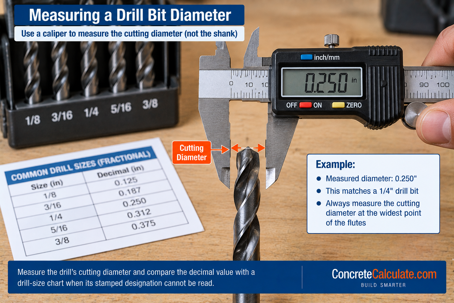
How to Measure Drill Bit Diameter
Where accuracy matters most.
For a standard twist drill, measure carefully across the cutting diameter at the outer margins, not across the web or body of the bit. A caliper works well for general use, while a micrometer provides higher accuracy for precision applications.
How to Choose the Right Drill Bit Size
The page’s primary decision framework.
Selection Workflow
Common Drill Bit Size Mistakes
Assuming #7 means 7 mm
Number drills use a completely separate designation system from metric millimeters.
Assuming higher number means larger drill
Number drills run in reverse; #80 is smallest and #1 is largest.
Assuming A is larger than Z
Letter drills increase from A (smallest) to Z (largest).
Confusing number drill with screw gauge
These are entirely separate numbering systems for different products.
Confusing letter drill with metric designation
A letter size is not a metric millimeter value.
Assuming nearest fractional size is exact
Nearest-fraction values are approximations, not precise equivalents.
Rounding metric sizes too aggressively
Small rounding errors can matter for tight-tolerance applications.
Using nominal screw diameter as pilot-hole diameter
Pilot holes are typically smaller than the screw’s outside diameter.
Using bolt diameter as clearance-hole diameter
Clearance holes are intentionally larger than the bolt for assembly.
Using clearance-hole size as tap-drill size
These serve opposite purposes: one passes through, the other cuts threads.
Using a tap-drill chart for structural bolt holes
Structural bolt holes follow different standards than threaded tap holes.
Assuming drill diameter equals finished-hole diameter exactly
Runout, wear, and material behavior can create small variations.
Ignoring tool runout
Worn chucks and bent bits can enlarge the actual finished hole.
Ignoring hole tolerance
Some applications need a tighter tolerance than a standard twist drill provides alone.
Measuring the wrong part of the drill
Always measure across the cutting diameter, not the web or shank.
Confusing shank diameter with cutting diameter
Reduced-shank bits can cut larger holes than their shank size suggests.
Assuming every 1/4-in hole requires a 1/4-in bit
The correct bit depends on the hole’s function, not just its nominal label.
Using standard twist-drill charts for masonry anchors without checking manufacturer data
Anchor hole sizing follows product listings, not generic drill charts.
Confusing countersink diameter with pilot or clearance drill diameter
These serve entirely different functions on the same fastener hole.
Confusing counterbore diameter with through-hole diameter
A counterbore recess diameter is separate from the pass-through hole below it.
Assuming every metric size has an exact fractional equivalent
Most metric-to-fractional conversions are close approximations, not exact matches.
Drill Bit Size Chart Limitations
Read Before Using for Precision or Structural Work
Drill size identifies nominal cutting diameter. Finished-hole diameter may differ from drill diameter due to runout, wear, and material behavior. Number and letter drill sizes are separate sizing systems from each other and from metric and fractional sizes. Fractional and metric equivalents shown as nearest values may be approximate, not exact. Tap-drill selection depends on the specific thread. Pilot-hole selection depends on the screw and material. Clearance-hole selection depends on the required fit class. Structural bolt-hole dimensions follow applicable structural standards. Concrete-anchor holes should follow manufacturer or listing requirements exactly. Precision holes may require reaming or boring after initial drilling. Tool availability varies by manufacturer and drill set.
Frequently Asked Questions
Download Drill Bit Size Chart PDF
Save or print this reference including the fractional, number, letter, and metric conversion tables, the unified master chart, and the drill selection workflow.