Pipe Support Spacing Chart 2026- Maximum Hanger Intervals
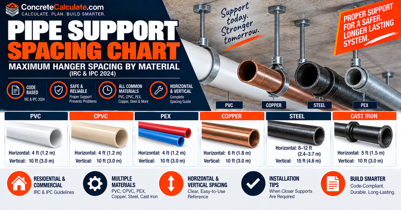
Pipe Support Spacing Chart
Maximum Hanger Intervals
Maximum horizontal and vertical pipe support spacing by material and size, based on the 2024 IRC and IPC, plus when closer supports are required.
 Reviewed by Muhammad Ramzan Babar, PhD Researcher (Plasma Physics) & Calculator Developer, View Profile
These are maximum support intervals, not target spacing for every installation
Closer support may be required by manufacturer instructions, temperature, pipe weight, fluid weight, valves and fittings, insulation, thermal movement, slope, vibration, seismic design, or engineering calculations. Always check the locally adopted code edition and any amendments.
Maximum Horizontal and Vertical Pipe Support Spacing
Based on 2024 IRC Table P2605.1, the residential plumbing piping support table.
| Piping Material | Size | Max Horizontal | Max Vertical | Special Note |
|---|---|---|---|---|
| ABS pipe | All | 4 ft | 10 ft* | Mid-story guide, 2 in and smaller |
| Cast iron | – | 5 ft** | 15 ft | **10 ft where 10-ft lengths used |
| Copper/alloy pipe | – | 12 ft | 10 ft | – |
| Copper tubing | ≤ 1-1/4 in | 6 ft | 10 ft | – |
| Copper tubing | ≥ 1-1/2 in | 10 ft | 10 ft | – |
| PEX | ≤ 1 in | 32 in | 10 ft* | Mid-story guide, 2 in and smaller |
| PEX | ≥ 1-1/4 in | 4 ft | 10 ft* | Mid-story guide, 2 in and smaller |
| CPVC | ≤ 1 in | 3 ft | 10 ft* | Mid-story guide, 2 in and smaller |
| CPVC | ≥ 1-1/4 in | 4 ft | 10 ft* | Mid-story guide, 2 in and smaller |
| PE-RT | ≤ 1 in | 32 in | 10 ft* | Mid-story guide, 2 in and smaller |
| PE-RT | ≥ 1-1/4 in | 4 ft | 10 ft* | Mid-story guide, 2 in and smaller |
| PP | ≤ 1 in | 32 in | 10 ft* | Manufacturer instructions may govern |
| PP | ≥ 1-1/4 in | 4 ft | 10 ft* | Manufacturer instructions may govern |
| PVC | – | 4 ft | 10 ft* | Mid-story guide, 2 in and smaller |
| Stainless drainage | – | 10 ft | 10 ft* | Mid-story guide, 2 in and smaller |
| Steel pipe | – | 12 ft | 15 ft | – |
Footnotes from the code: for several materials 2 in and smaller, a guide is required midway between vertical supports to prevent movement perpendicular to the pipe axis; cast-iron horizontal spacing may increase to 10 ft where 10-ft pipe lengths are installed.
Critical Note
These are maximum support intervals, not target spacing for every installation. Closer support may be required by manufacturer instructions, temperature, pipe weight, fluid weight, valves/fittings, insulation, thermal movement, slope, vibration, seismic design, or engineering calculations.
What Is Pipe Support Spacing?
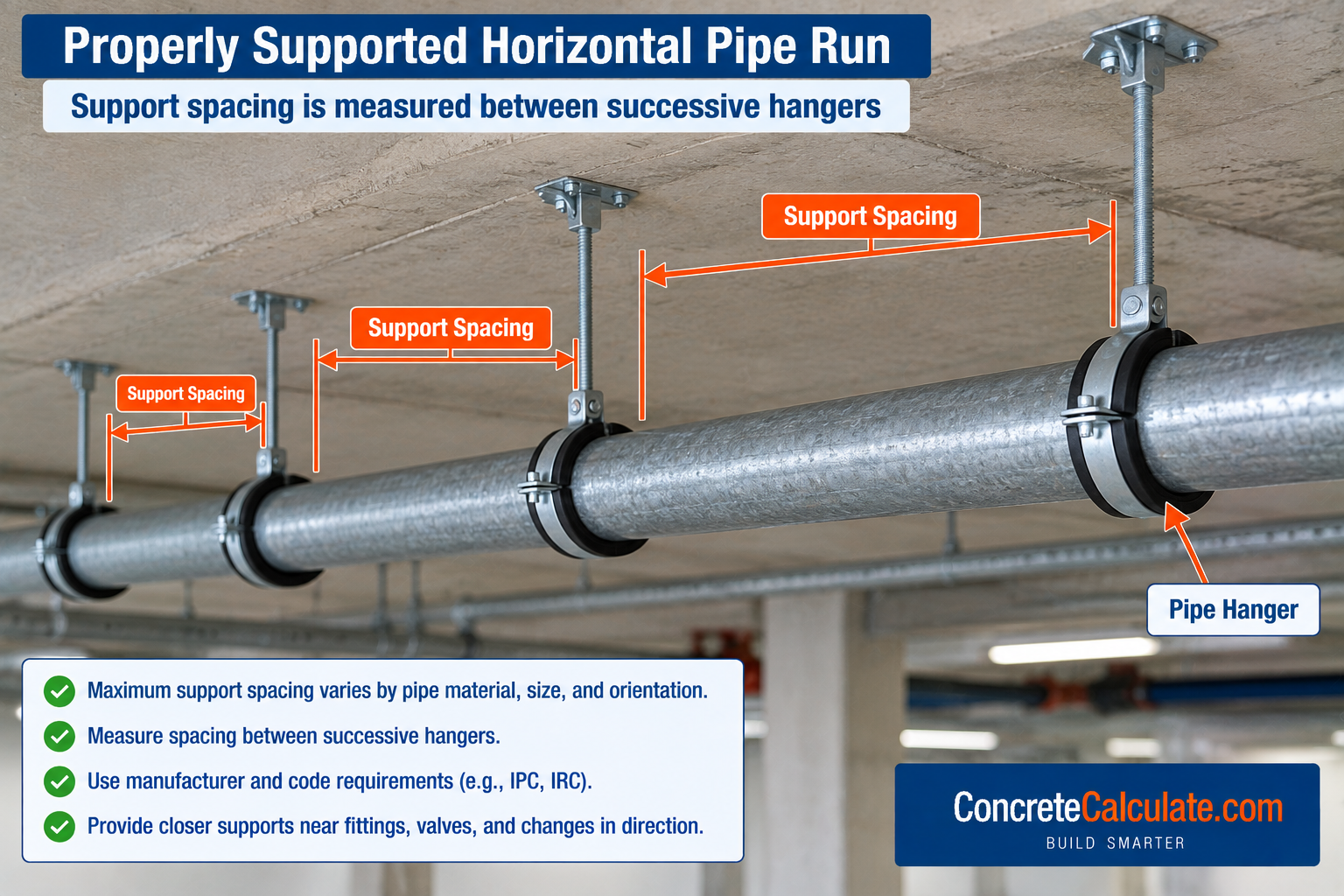
The maximum distance permitted between supports carrying or restraining a pipe run.
Pipe support spacing is the maximum distance permitted or recommended between hangers, clamps, straps, guides, or other supports carrying or restraining a pipe run. Spacing affects sag, alignment, slope, joint stress, vibration, thermal movement, pipe stress, and hanger loads.
Pipe Support vs Hanger vs Clamp vs Guide vs Anchor
An important terminology section that raises this page above generic hanger-spacing articles.
| Term | Definition |
|---|---|
| Support | General device carrying pipe weight |
| Hanger | Suspended support carrying pipe from above |
| Clamp | Grips or restrains pipe at a support |
| Guide | Allows axial movement but limits transverse movement |
| Anchor | Restrains movement in defined directions |
Important
A guide or anchor does not serve exactly the same function as a simple gravity hanger; each is selected based on the movement and load conditions at that specific point in the piping system.
Horizontal vs Vertical Pipe Support Spacing
Why the two values differ so much for the same material.
| Orientation | Primary Concern |
|---|---|
| Horizontal pipe | Bending, sag, slope, concentrated loads |
| Vertical pipe / risers | Pipe weight, vertical load transfer, lateral guiding, thermal movement |
One material can have 4 ft horizontal spacing but 10 ft vertical spacing, since the governing physical concern is different in each orientation.
2024 IRC Pipe Support Spacing Requirements
The key authority section for residential plumbing.
The 2024 IRC Table P2605.1 explicitly lists maximum horizontal and vertical support spacing by piping material for the residential plumbing context. Always check the locally adopted code edition and amendments, since some U.S. jurisdictions use the IRC, IPC, UPC, or state and city amendments that may differ from the base code values shown here.
✓ Verified Against 2024 IRC Table P2605.12024 IPC Pipe Hanger Spacing
The broader commercial and general plumbing counterpart.
The 2024 IPC requires piping to be supported in accordance with Table 308.5, with an exception for systems specifically engineered for expansion and contraction. The IPC Table 308.5 values match the IRC Table P2605.1 values for the materials covered in this chart, giving this page relevance for both residential and broader commercial plumbing audiences.
✓ Verified Against 2024 IPC Table 308.5Steel and Black Iron Pipe Support Spacing
The steel pipe category from the code table.
| Pipe Material | Horizontal | Vertical |
|---|---|---|
| Steel pipe | 12 ft | 15 ft |
This is a plumbing-code support interval, not a universal engineered process-piping span for every size, schedule, temperature, or service. Do not treat 12 ft as an engineered maximum span for hot steam, heavy valves, large process piping, or vibration-sensitive systems. See the Black Iron Pipe Size Chart, Pipe Weight Chart, and Pipe Schedule Chart for related dimensional and weight data.
Galvanized Steel Pipe Support Spacing
Same dimensional and support family as black steel pipe.
The general IRC support category for steel pipe gives 12 ft horizontal and 15 ft vertical spacing. Galvanizing does not create a completely separate support-spacing family; it is a surface coating applied to the same underlying steel pipe dimensional system. See the Galvanized Pipe Size Chart for the complete galvanized dimensional reference.
Copper Pipe and Copper Tubing Support Spacing
Requires careful differentiation between pipe and tubing.
| Copper Product | Horizontal | Vertical |
|---|---|---|
| Copper or copper-alloy pipe | 12 ft | 10 ft |
| Copper tubing ≤ 1-1/4 in | 6 ft | 10 ft |
| Copper tubing ≥ 1-1/2 in | 10 ft | 10 ft |
The Copper Development Association separately gives practical guidance for drawn copper tube at approximately 8-ft horizontal intervals for 1 in and smaller and 10 ft for larger sizes, unless applicable plumbing-code requirements say otherwise, with vertical runs generally supported about every 10 ft per story. Code tables and manufacturer or industry recommendations are not always numerically identical; use whichever requirement is applicable to the specific project. See the Copper Pipe Size Chart for complete copper dimensional data.
PVC Pipe Support Spacing Chart
A common thermoplastic drainage and pressure piping material.
| Material | Horizontal | Vertical |
|---|---|---|
| PVC pipe | 4 ft | 10 ft* |
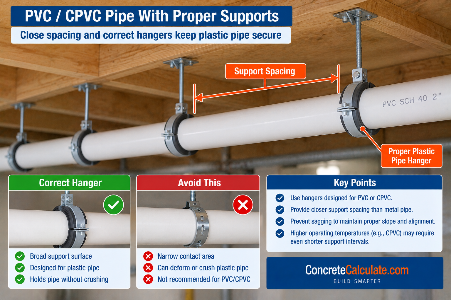
Manufacturer technical guidance independently confirms that common plumbing codes generally limit ABS and PVC horizontal hanger spacing to 4 ft, while emphasizing that support must also consider operating temperature, fittings, and local code requirements. See the PVC Pipe Size Chart for complete dimensional data.
CPVC Pipe Support Spacing Chart
A size-dependent spacing pattern within a single material.
| Size | Horizontal | Vertical |
|---|---|---|
| CPVC ≤ 1 in | 3 ft | 10 ft* |
| CPVC ≥ 1-1/4 in | 4 ft | 10 ft* |
Manufacturer guidance independently confirms this same general code pattern: 3 ft for 1 in and smaller and 4 ft for 1-1/4 in and larger. Temperature-sensitive plastic systems may require manufacturer-specific closer spacing beyond this base code value.
PEX Pipe Support Spacing Chart
Where manufacturer systems matter greatly beyond the base code table.
| Size | Horizontal | Vertical |
|---|---|---|
| PEX ≤ 1 in | 32 in | 10 ft* |
| PEX ≥ 1-1/4 in | 4 ft | 10 ft* |
Uponor’s bare PEX-a installation guidance uses the same IPC-aligned base spacing: 32 in for 1 in and smaller, and up to 48 in for 1-1/4 in and larger under some codes, with vertical support approximately every 5 ft. Where code, listing, and manufacturer instructions differ, the actual project must satisfy the applicable adopted code and listed installation requirements. See the PEX Pipe Size Chart for complete PEX dimensional data.
PEX With Continuous Pipe Support
An excellent example of proprietary systems extending code spacing.
Uponor’s proprietary PEX-a Pipe Support can increase horizontal support spacing to as much as 8 ft when installed in accordance with its system requirements. For higher temperature-differential applications, clamps or fixed points are also required per the manufacturer’s instructions, with clamping typically specified at a maximum on-center interval to control thermal expansion. This demonstrates that “PEX spacing equals 32 inches” is not universally true for every engineered or listed PEX support system.
Important
Do not treat proprietary continuous-support values as universal PEX rules. The 8-ft spacing applies specifically to the manufacturer’s listed support product, installed per its instructions, not to bare unsupported PEX pipe.
ABS Pipe Support Spacing
Matches the PVC spacing pattern under the current code.
| Material | Horizontal | Vertical |
|---|---|---|
| ABS pipe | 4 ft | 10 ft* |
Manufacturer technical guidance likewise confirms common plumbing-code support at 4 ft for both ABS and PVC.
Cast-Iron Pipe Support Spacing
Includes an important length-based exception.
| Material | Horizontal | Vertical |
|---|---|---|
| Cast-iron pipe | 5 ft** | 15 ft |
Important Exception
Horizontal spacing can increase to 10 ft where 10-ft pipe lengths are installed, per the table footnote. Joints also need appropriate support and installation treatment according to the specific piping system used.
PE-RT, PEX-AL-PEX, and Polypropylene Support Spacing
Related modern plastics grouped together rather than split into thin separate sections.
| Material | Size | Horizontal | Vertical |
|---|---|---|---|
| PE-RT | ≤ 1 in | 32 in | 10 ft* |
| PE-RT | ≥ 1-1/4 in | 4 ft | 10 ft* |
| PP | ≤ 1 in | 32 in | 10 ft* |
| PP | ≥ 1-1/4 in | 4 ft | 10 ft* |
| PEX-AL-PEX | < 1 in | 32 in | 4 ft |
| PEX-AL-PEX | ≥ 1 in | 4 ft | 10 ft* |
The 2024 IRC also includes manufacturer-based provisions and footnotes for these composite and polypropylene systems, allowing spacing to be increased to the manufacturer’s installation requirements based on maximum operating temperature design or incorporation of pipe/tube supports per the manufacturer’s instructions.
✓ Verified Against 2024 IRC Table P2605.1Stainless Steel Drainage Pipe Support Spacing
A drainage-specific category, not a general stainless process piping value.
| Material | Horizontal | Vertical |
|---|---|---|
| Stainless steel drainage systems | 10 ft | 10 ft* |
Do not extrapolate this drainage-system value to all stainless process piping; process and industrial stainless systems have their own engineering-based support requirements.
Why Pipe Material Changes Support Spacing
The fundamental physical explanation behind the entire chart.
Support spacing depends partly on elastic stiffness, creep behavior, temperature sensitivity, pipe or tube geometry, weight, and joint system. Rigid steel can typically span farther than flexible thermoplastic tubing in ordinary plumbing applications, which is why steel allows 12 ft while PEX 1 in and smaller allows only 32 in under the same code table.
Does Pipe Size Change Support Spacing?
Sometimes, at specific size thresholds.
Examples from the code include copper tubing changing spacing at the 1-1/4 to 1-1/2 in transition, PEX changing at the 1 to 1-1/4 in transition, CPVC changing at the same threshold, and PE-RT and polypropylene changing likewise. For engineered metal piping, size also affects pipe weight, bending stiffness, support load, and sag behavior in ways not captured by the plumbing code table.
Pipe Weight and Support Loads
A support carries more than just the empty pipe.
Formula
W(support) ≈ W(pipe) + W(fluid) + W(insulation) + W(attachments)
Support selection must consider pipe self-weight, contained fluid, insulation, and valves or fittings. The IPC requires hangers and supports to support the piping and its contents, and its general support provisions address approved support materials and structural attachment. See the Pipe Weight Chart for empty and filled pipe weight data.
Empty Pipe vs Water-Filled Pipe Support Loads
The operating condition, not empty pipe, is normally the governing case.
Formula
W(fluid) = ρ × V
A pipe support system is normally concerned with the operating or load condition, not just empty pipe. Large-diameter, fluid-filled pipe can weigh substantially more than empty pipe. See the Pipe Volume Chart and Pipe Weight Chart for the volume and weight calculations behind this consideration.
Temperature and Pipe Support Spacing
Essential, especially for plastic piping systems.
Manufacturer technical guidance states that support spacing for horizontal plastic systems must consider the maximum operating temperature, publishing recommended spacing according to size, schedule, and operating temperature. Higher temperature reduces thermoplastic stiffness, increases sag, and increases thermal movement, requiring closer supports in many cases. A room-temperature spacing table cannot automatically be used for hot CPVC or PVC process piping.
Thermal Expansion, Guides, and Anchors
Support spacing is not the same question as thermal restraint.
The IPC expressly allows an exception where expansion and contraction support intervals are established by engineered design. A hanger carries weight, a guide directs movement, an anchor restrains movement, and an expansion loop or offset accommodates growth. For PEX, manufacturer support systems can use special clamps and fixed points to control movement in higher temperature-differential applications.
Support Spacing Near Valves, Fittings, and Equipment
A major real-world issue that regular-interval hangers alone do not address.
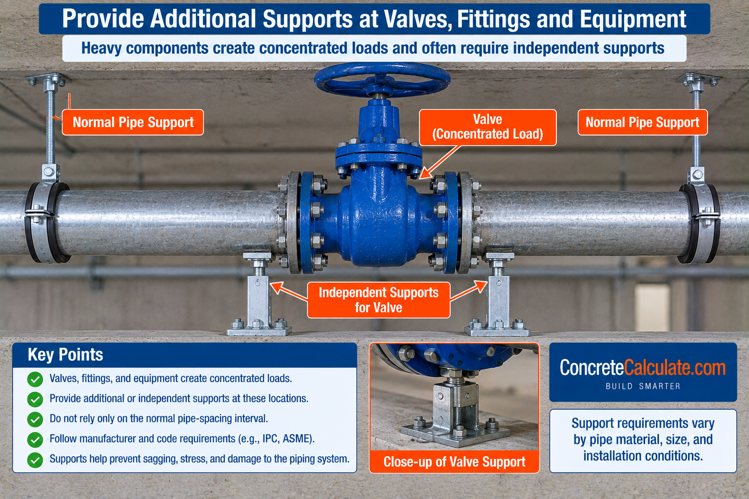
Heavy items such as large valves, strainers, flanges, backflow preventers, pumps, and meters introduce concentrated loads. Manufacturer technical guidance recommends supporting changes in direction close to fittings to avoid excessive stresses, and notes that heavy valves and fittings affect required spacing.
Core Message
Do not simply place hangers at regular maximum intervals and ignore concentrated loads; heavy components often need an independent or closer support.
Pipe Supports Near Changes in Direction
Elbows and tees can need closer support for several reasons.
Elbows and tees can need closer support due to torsion, thermal movement, weight, and branch loads. Manufacturer guidance explicitly recommends supporting changes in direction as close as practical to the fitting.
Pipe Support Spacing for Sloped Drainage Pipe
Maximum allowed spacing does not automatically preserve required slope.
Support must maintain required slope, alignment, and drainage grade. Sagging between supports can create bellies, standing water, or grade reversal. Therefore maximum hanger spacing may still be too wide if it fails to preserve slope in a real installation, particularly relevant for PVC DWV, ABS, and cast iron drainage piping.
Vertical Riser Supports and Mid-Story Guides
A nuance that materially improves this chart over generic competitors.
The 2024 IRC footnote requires, for several materials 2 in and smaller, a guide installed midway between required vertical supports to prevent movement perpendicular to the pipe axis. Vertical spacing described as “support every 10 ft” does not necessarily mean the pipe needs no intermediate guiding within that interval.
✓ Verified Against 2024 IRC Table P2605.1 FootnotePipe Hanger and Support Types
Common support forms, kept concise rather than a product catalog.
| Support Type | Common Use |
|---|---|
| Clevis hanger | General suspended pipe support |
| Loop hanger | Lighter pipe, easy field installation |
| Split-ring hanger | Adjustable suspended support |
| Pipe clamp | Wall or structure-mounted rigid support |
| Roller support | Allows axial movement under load |
| Trapeze support | Multiple parallel pipe runs on one frame |
| Strut support | Rigid framed support systems |
| Pipe strap | Light-duty fastening to framing |
Support type selection depends on expected movement, load, pipe material, temperature, and insulation, not on spacing distance alone.
Metal Hangers on Copper and Plastic Pipe
An important compatibility consideration often overlooked.
The IPC requires approved hanger and support materials that do not promote harmful galvanic action. Manufacturer guidance for plastic pipe also warns that supports must not compress, distort, cut, or abrade the piping. Copper and steel contact considerations, broad-bearing plastic support requirements, and abrasion protection at support points all matter for long-term piping performance.
ANSI/MSS SP-58-2025 Pipe Hanger and Support Standard
The main professional and industrial standard section, with a genuine freshness advantage.
ANSI/MSS SP-58-2025 is now the current revision, superseding the older SP-58-2018 edition. It establishes an industry-accepted basis for the materials, design, manufacture, selection, application, and installation of pipe hangers and supports across service temperatures.
Important
The professional hanger and support reference is now the 2025 edition, published September 2025. Do not cite the 2018 edition as current.
Plumbing-Code Spacing vs Engineered Pipe Support Spacing
Probably the most important expert distinction on this entire page.
| Approach | Basis |
|---|---|
| Code table | Prescriptive maximum intervals for ordinary plumbing installations |
| Engineered piping | Actual loads, pipe size/schedule, stress, sag/deflection, temperature, equipment, vibration, movement, seismic requirements |
ASME’s B31.3 process piping design guidance treats pipe support design as involving pipe support stresses, loads on supporting elements, standard and special supports, load ratings, and support reactions. Do not use the IRC or IPC quick table as an engineered process-piping span table.
Seismic Bracing vs Ordinary Pipe Support
A distinction that deserves explicit attention.
Gravity hangers and supports are not automatically seismic bracing. The IPC support provisions separately address seismic support where earthquake loads apply. Gravity support carries weight; seismic restraint limits earthquake-induced movement. This chart does not provide simplified seismic spacing values, since seismic bracing requires project-specific engineering based on applicable seismic design category and local requirements.
How to Determine Pipe Support Spacing
The principal practical decision section for this page.
Support Spacing Workflow
Common Pipe Support Spacing Mistakes
Using one hanger spacing for every material
Each piping material has its own code-listed maximum spacing.
Assuming all pipe can be supported every 10 ft
Spacing varies from 32 in to 15 ft depending on material and orientation.
Using steel spacing for PVC
Steel allows 12 ft horizontal; PVC allows only 4 ft.
Using copper-pipe spacing for copper tubing
Copper pipe and copper tubing have different code-listed values.
Ignoring pipe size thresholds
Several materials change allowed spacing at specific size breakpoints.
Assuming all PEX uses 32-in spacing
PEX 1-1/4 in and larger is allowed up to 4 ft under the base code.
Applying proprietary 8-ft PEX support spacing to unsupported PEX
The 8-ft value applies only to the specific listed continuous support product.
Ignoring temperature effects on plastics
Higher temperature can require closer spacing than the base table.
Supporting empty pipe but ignoring fluid weight
Operating (filled) weight is normally the governing load case.
Ignoring insulation weight
Insulation adds load that the support system must carry.
Ignoring valves and fittings
Concentrated loads from heavy components need independent consideration.
Putting hangers only at maximum intervals
Maximum spacing is a ceiling, not a target for every installation.
Failing to support changes in direction
Elbows and tees often need support closer than the standard interval.
Letting drainage pipe sag between supports
Sag can reverse slope and cause standing water even within code spacing.
Confusing a hanger with a guide
Hangers carry weight; guides control transverse movement.
Confusing a guide with an anchor
Guides allow axial movement; anchors restrain movement entirely.
Ignoring vertical mid-story guide requirements
Several materials 2 in and smaller need a guide between main vertical supports.
Assuming galvanizing changes steel spacing category
Galvanized and black steel share the same steel pipe spacing category.
Using plumbing-code spacing for process piping
Engineered process piping requires a full engineering-based analysis.
Ignoring local code amendments
The adopted local code edition governs, not necessarily the base IRC or IPC.
Ignoring manufacturer installation instructions
Listed products can have their own spacing and clamping requirements.
Assuming support spacing is seismic bracing spacing
Seismic restraint is a separate design requirement from gravity support spacing.
Using a support that damages or abrades plastic pipe
Supports must not compress, distort, cut, or abrade the piping material.
Creating galvanic corrosion at dissimilar-metal supports
Hanger and support materials must not promote harmful galvanic action.
Pipe Support Spacing Chart Limitations
Read Before Using for Installation or Design
Code edition and jurisdiction matter; always verify the locally adopted code. IRC and IPC values are maximum prescriptive intervals for applicable plumbing installations, not universal engineered spans. Manufacturer requirements can be more restrictive than the base code table. Temperature can reduce allowable plastic-pipe spacing. Pipe size can change spacing at specific thresholds. Fluid, insulation, and fittings add support load beyond empty pipe weight. Valves and equipment can require local, independent supports. Vertical piping can need guides between main supports. Expansion and contraction can require engineered anchors and guides. Process and power piping require more detailed engineering than the plumbing code table provides. Seismic bracing is a separate design issue not addressed by this chart. Actual support hardware must have adequate capacity and compatible material and contact surfaces for the specific pipe material used.
Frequently Asked Questions
Download Pipe Support Spacing Chart PDF
Save or print this reference including the 2024 IRC/IPC quick-reference table, material-specific spacing sections, temperature and load considerations, and the support spacing decision workflow.