Roof Purlin Size Chart 2026: Cold-Formed Steel C & Z Purlins
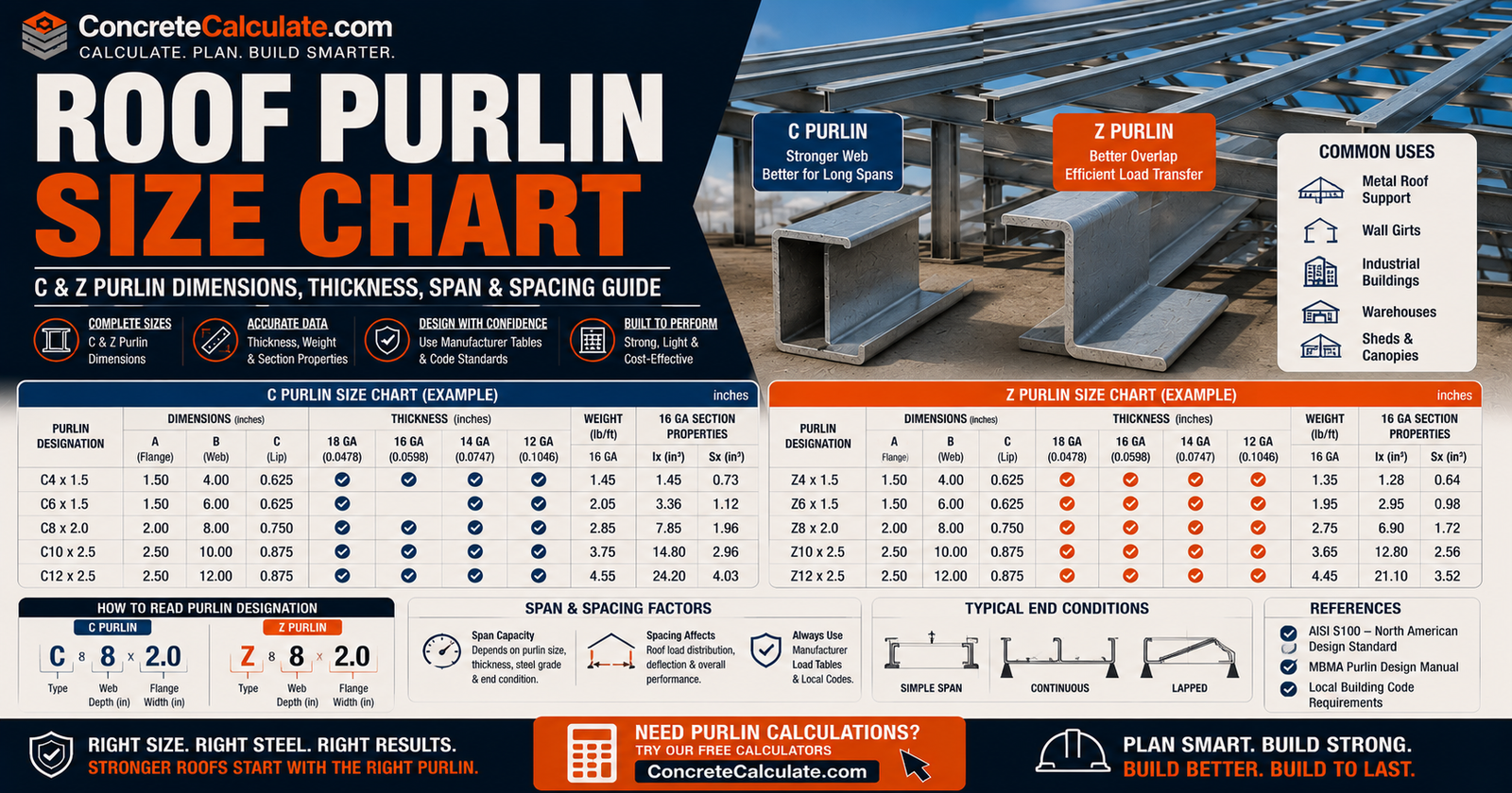
Roof Purlin Size Chart
Cold-Formed Steel C & Z Purlins
How C-purlin and Z-purlin dimensions, thickness, and gauge work, why span and spacing are not the same thing, and why purlin size cannot be selected from depth or span alone in a metal building roof system.
 Reviewed by Muhammad Ramzan Babar, PhD Researcher (Plasma Physics) & Calculator Developer, View Profile
Purlin depth or gauge does not have one universal allowable span
This chart explains cold-formed steel purlin dimensions and terminology so you can correctly read a manufacturer or AISI load table. It does not publish a “20-ft span = 8-in. purlin” style chart, because no such universal table exists. Use the applicable manufacturer or AISI S100 load table for the exact section, roof system, load combination, and bracing condition.
Roof Purlin Size Chart, Quick Reference
Three separate opening references are used here, because dimensions and structural capacity should never be mixed into one misleading chart.
Common Cold-Formed Steel Purlin Size Reference
| Purlin Family | Typical Nominal Depth | Common Flange Range | Common Base Thickness Range | Typical Availability |
|---|---|---|---|---|
| Shallow purlins | ~6 in. | 1.5 to 2 in. | 0.033 to 0.070 in. | Common |
| Medium purlins | ~8 to 10 in. | 2 to 2.5 in. | 0.043 to 0.097 in. | Very common |
| Deep purlins | ~12 to 16 in. | 2.5 to 3.5 in. | 0.054 to 0.118 in. | Common for longer bays |
These are general classification ranges, not a universal standardized size series. Exact section dimensions, lip geometry, flange widths, and thickness options vary by manufacturer.
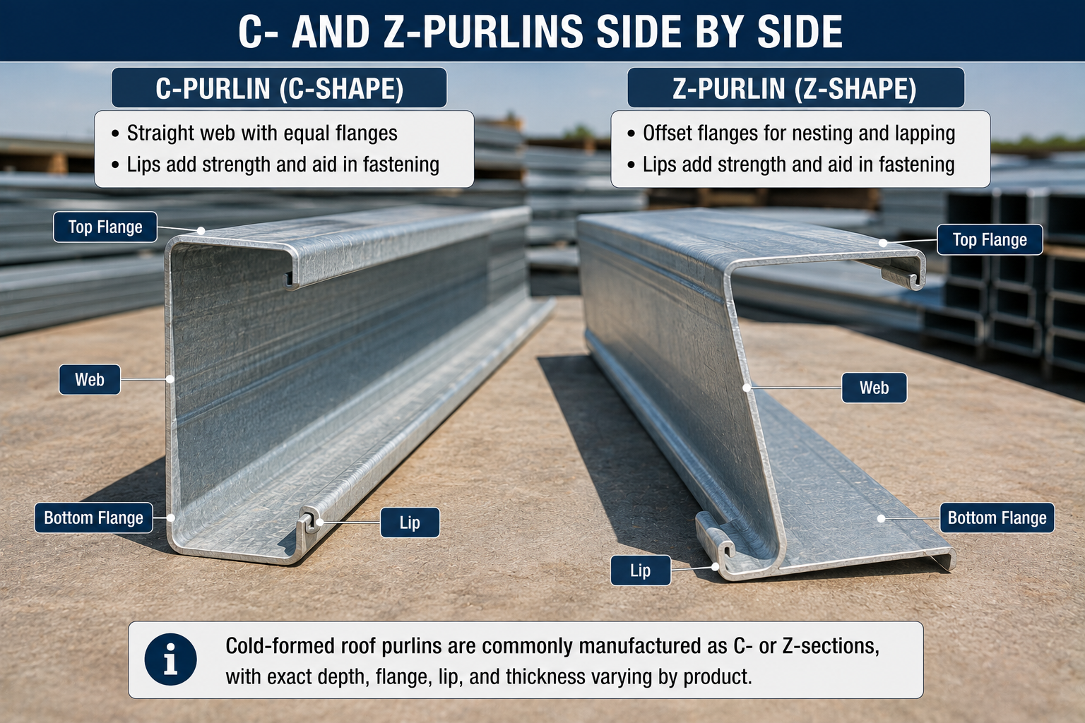
Z-Purlin vs C-Purlin Quick Chart
| Feature | Z-Purlin | C-Purlin |
|---|---|---|
| Cross-section | Z | C |
| Common continuous/lap use | Excellent | Less convenient |
| Nesting/lapping | Yes | Limited/different |
| Principal-axis behavior | Unsymmetric/oblique | Singly symmetric |
| Typical metal-building use | Very common | Common in selected locations |
| Capacity | Project-specific | Project-specific |
MBMA specifically treats both Z- and C-sections and notes important differences in their lateral and torsional behavior. Section dimension ranges above reflect commonly seen manufacturer product families, not a national standard.
Purlin size does not equal allowable span
A purlin depth or gauge does not have one universal allowable span. Use the applicable manufacturer or AISI S100 load table for the exact section, roof system, load combination, and bracing condition.
What Is a Roof Purlin?
A secondary roof framing member spanning between primary frames, rafters, or trusses and supporting the roof panels or decking.
In metal buildings, purlins commonly support metal roof panels, transfer gravity loads to primary framing, resist wind uplift, and participate in roof diaphragm and bracing behavior. MBMA’s current guide describes cold-formed steel purlins as integral parts of roof-panel, diaphragm, and anchorage systems, not isolated beams.
Steel Purlins vs Wood Purlins
The search phrase “roof purlin size” is ambiguous, so this distinction appears early.
Cold-Formed Steel Purlins
The main subject of this chart. Used extensively in metal buildings, warehouses, industrial buildings, agricultural structures, and commercial metal roofs.
Wood Purlins
In conventional wood roof framing, “purlin” can mean a member used to reduce rafter span. The IRC’s wood-rafter purlin provision requires the purlin to be not smaller than the rafters it supports, with prescribed bracing requirements. For wood roof framing reference, see the Roof Rafter Size Chart and Roof Rafter Span Chart.
Z-Purlins vs C-Purlins
One of the page’s major structural sections.
Z-Purlins
Advantages in many metal-building systems include easy overlapping or lapping at supports, continuous multi-span systems, and efficient material use.
C-Purlins
Common for simple-span conditions, end conditions, and selected structural layouts.
MBMA explains that Z- and C-sections respond differently to lateral and torsional effects because Z-sections have oblique principal axes while C-sections have their principal axes aligned with the geometric axes and have an offset shear center.
✓ Verified against AISI S100-16 (2020) with Supplement 2How to Read a Purlin Size Designation
Critical, because purlin naming is not as nationally standardized as AISC W-shape naming.
Manufacturer designations may communicate nominal depth, flange width, steel thickness, product series, and section type.
Example: 8ZS2.25×070
Do not assume every manufacturer interprets an alphanumeric purlin designation identically. Confirm the exact designation convention with the specific manufacturer’s technical documentation.
Roof Purlin Dimension Anatomy
Important geometric terms used throughout purlin catalogs.
| Term | Description |
|---|---|
| Depth (d) | Overall web depth |
| Flange width (b) | Horizontal flange dimension |
| Lip / stiffener | Edge return that improves local stability |
| Base steel thickness (t) | Actual structural steel thickness before coatings |
| Inside bend radius | Affects section properties |
Z-Purlin Size Chart
Dimensional data by section family, based on real published AISI design example data.
Shallow Z-Purlins
| Designation | Depth (in) | Flange (in) | Base Thickness (in) |
|---|---|---|---|
| 6ZS2x059 | 6 | 2.00 | 0.059 |
Medium Z-Purlins
| Designation | Depth (in) | Flange (in) | Base Thickness (in) |
|---|---|---|---|
| 8ZS2.25×059 | 8 | 2.25 | 0.059 |
| 8ZS2.25×070 | 8 | 2.25 | 0.070 |
Deep Z-Purlins
| Designation | Depth (in) | Flange (in) | Base Thickness (in) |
|---|---|---|---|
| 10ZS2.5×070 | 10 | 2.50 | 0.070 |
The 8ZS2.25×059 and 8ZS2.25×070 designations shown above are from an actual published AISI/CFSEI structural design example for a four-span metal building Z-purlin line supporting a standing-seam roof. Other depths shown follow the same manufacturer designation logic but should be verified against the specific product line before use; do not mix dimensions from different manufacturers into one fictional standardized profile.
C-Purlin Size Chart
Organized by depth to compare with Z-sections of similar nominal depth.
| Family | Typical Depth Range | Typical Flange Range |
|---|---|---|
| Shallow C-purlins | ~6 in. | 1.5 to 2 in. |
| Medium C-purlins | ~8 to 10 in. | 2 to 2.5 in. |
| Deep C-purlins | ~12 in. and larger | 2.5 to 3.5 in. |
These are classification ranges only; exact dimensions and thickness options for a specific C-purlin product must be taken from the manufacturer’s current catalog or AISI-based load table.
Purlin Depth Chart
Common depth terminology, labeled as classification only, not span guidance.
| Nominal Depth | Typical Section Family | Common Use Context |
|---|---|---|
| ~6 in. | Shallow | Shorter or lighter systems |
| ~8 in. | Medium | Common metal-building use |
| ~10 in. | Medium/deep | Longer or heavier conditions |
| ~12+ in. | Deep | Larger spans/load demands |
Increasing depth generally increases bending stiffness and capacity, but thickness, flange geometry, bracing, load direction, continuity, and local or distortional buckling also matter. This is classification only, not allowable span guidance.
Purlin Flange Width and Lip Size
Why two “8-inch purlins” can have very different capacities.
Variables include flange width, lip length, bend geometry, and steel thickness. These influence local buckling, distortional buckling, torsional stiffness, and roof-panel attachment. This is an important reason not to compare purlins by depth alone.
Purlin Thickness Chart
Base steel thickness in inches, mils, and millimeters.
| Base Steel Thickness (in.) | Mil | mm |
|---|---|---|
| 0.018 | 18 | 0.46 |
| 0.027 | 27 | 0.69 |
| 0.033 | 33 | 0.84 |
| 0.043 | 43 | 1.09 |
| 0.054 | 54 | 1.37 |
| 0.068 | 68 | 1.73 |
| 0.097 | 97 | 2.46 |
| 0.118 | 118 | 3.00 |
Base steel thickness first; gauge is only a manufacturer or market reference and should not be treated as the primary engineering field.
Gauge vs Actual Purlin Thickness
This section can prevent a serious material-ordering error.
Gauge label, design or base metal thickness, and coated thickness are three separate concepts. Industry standards specify that minimum base steel thickness represents 95% of the design thickness, and that this minimum acceptable thickness is the value delivered to the jobsite.
Key message
Two products both casually called “14 gauge” should not be assumed structurally identical unless their specified base steel thickness and grade match.
Purlin Weight per Foot Chart
Useful for material estimates, shipping, and erection, but not a proxy for capacity.
| Column | Description |
|---|---|
| Purlin section | Full manufacturer designation |
| Thickness | Base steel thickness |
| Area | Net cross-sectional area |
| Weight lb/ft, kg/m | Nominal weight per unit length |
Weight is useful for comparing alternatives and estimating material and shipping costs, but do not use weight as a proxy for structural capacity. For weight calculations on a specific section, see the steel weight calculator or metal weight calculator.
Purlin Section Properties
Columns that belong in a high-quality cold-formed purlin chart.
| Property | Description |
|---|---|
| Area (A) | Net cross-sectional area |
| Ix, Iy | Moment of inertia about geometric axes |
| Ixy | Product of inertia, nonzero for Z-sections due to their asymmetry |
| Sx | Section modulus about the x-axis |
| Radius of gyration | Used in slenderness and buckling checks |
| Torsional constant (J), warping constant (Cw) | Used in torsional and lateral-torsional buckling analysis |
AISI cold-formed design examples explicitly use properties such as Ix, Iy, Ixy, Cw, and J when analyzing Z-purlins, since Z-sections are not doubly symmetric and their principal axes are rotated relative to the geometric x and y axes. This page does not turn these properties into a full cold-formed steel mathematics article.
What Determines Roof Purlin Size?
The most important selection section on this page.
Purlin span
Distance between primary supports.
Purlin spacing
Tributary roof width per purlin line.
Dead load
Roof panel, insulation, and any supported ceilings or services.
Roof live load, snow, and drift
Includes sloped-roof snow, unbalanced snow, and drifting per ASCE 7-22.
Wind uplift
Reverses bending direction compared with gravity load.
Roof slope
Affects load components relative to the purlin web.
Steel grade and thickness
Directly controls section strength.
Continuity/laps
Continuous systems redistribute moment differently than simple spans.
Roof-panel restraint
Panel type and connection affect lateral bracing of the purlin.
Bridging and bracing
Discrete bracing elements affect buckling capacity.
Deflection limits
Serviceability requirements can govern before strength does.
Purlin size cannot be selected correctly from span alone.
Roof Loads Used to Size Purlins
ASCE/SEI 7-22 is the current national load framework.
ASCE 7-22 covers dead load, roof live load, snow, rain, wind, tornado where applicable, seismic effects, and load combinations.
Gravity Load
Downward load from dead, live, snow, and rain sources.
Wind Uplift
Upward roof pressure that reverses the bending direction.
Snow, Unbalanced Snow, and Drift
ASCE 7-22 specifically includes sloped-roof snow, partial loading, unbalanced snow, drifts, sliding snow, and rain-on-snow. This makes a simple “psf to purlin size” chart inherently project-specific.
✓ Verified against ASCE/SEI 7-22Purlin Spacing Chart
Framed correctly, using a real manufacturer example rather than a universal rule.
Formula
w = qS, where q is roof pressure or load in psf, S is purlin spacing in feet, and w is the resulting line load in plf.
| Condition (Nucor Example) | Minimum Spacing | Maximum Spacing |
|---|---|---|
| Roof slope < 1/2:12 | 1 ft 10 in. | 3 ft 10 in. |
| Roof slope ≥ 1/2:12 | 1 ft 10 in. | 5 ft 6 in. |
These specific spacing values are from one manufacturer’s system documentation, labeled here as a real example, not a universal purlin-spacing rule. Some roof panel approvals separately restrict maximum spacing to about 5 ft regardless of the purlin’s own structural capacity. Roof-panel allowable span can control purlin spacing independently of purlin structural capacity.
Purlin Span vs Purlin Spacing
Commonly confused, and deserving a clear visual distinction.
| Term | Definition |
|---|---|
| Span | Distance along the purlin between primary frames |
| Spacing | Distance between adjacent parallel purlins |
Example: Tributary Load per Purlin
How to Use a Roof Purlin Span/Load Table
Instead of publishing a fake universal span table, this section teaches you how to use a real one.
Typical manufacturer load-table columns include section designation, span, number of spans, gravity allowable load, uplift allowable load, deflection-limited load, and bracing condition.
This workflow is much safer and more technically useful than an oversimplified size chart.
Equipment for Your Project
Affiliate disclosure: As an Amazon Associate, ConcreteCalculate earns from qualifying purchases. We may also earn a commission from other affiliate links at no additional cost to you.
Single-Span vs Continuous Purlins
A key structural distinction.
| Type | Description |
|---|---|
| Single span | One member between two supports |
| Continuous purlin | Spans across multiple frames, may use laps at supports, redistributing moment |
MBMA’s 2024 guide devotes an entire chapter to continuous purlin design, confirming that continuity and lapping are a core part of roof-purlin design.
Lapped Z-Purlin Systems
One of the strongest purlin-specific sections on this page.
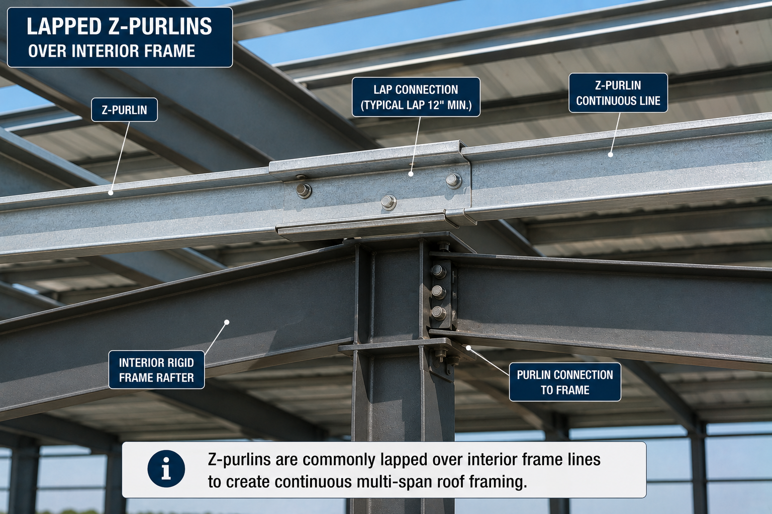
Z-purlins are commonly overlapped at interior frames, bolted through webs or flanges depending on the system, and designed as continuous lines.
Lap Length
Project and manufacturer specific.
Double Section at Lap
Changes stiffness and strength locally where the two purlins overlap.
End Span vs Interior Span
Can require different sections, as shown in the AISI four-span example above, where exterior spans used a heavier 070 mil section and interior spans used a lighter 059 mil section within the same purlin line.
Do not assume a universal “lap equals 10 percent of span” rule. MBMA’s guide explicitly evaluates forces at the purlin lap and the ends of laps in continuous systems on a project-specific basis.
Purlin Bracing, Bridging, and Restraint
Essential context, since purlins are thin-walled cold-formed members.
Purlins often rely on roof-panel restraint, discrete bridging, anti-roll devices, flange braces, and anchorage. The 2024 IBC specifically identifies purlin and girt restraint, bridging, and bracing as items subject to special inspection in metal building systems.
A purlin capacity table is only valid for its stated restraint conditions.
Roof Panels as Purlin Bracing
A key advanced differentiator for this page.
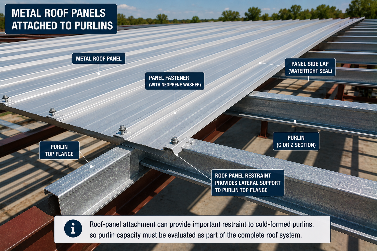
MBMA explains that roof panels can provide lateral support to purlins, but effectiveness depends on panel profile, the panel-to-purlin connection, fixed versus sliding clips, insulation, and diaphragm stiffness. Standing-seam systems can provide less reliable lateral restraint than direct through-fastened systems because the clip permits movement.
The same purlin can have different usable capacity under different roof-panel systems.
Through-Fastened vs Standing-Seam Roof Systems
A direct comparison of how each system restrains purlins.
| Feature | Through-Fastened | Standing Seam |
|---|---|---|
| Attachment | Panel fastener directly to purlin | Clips |
| Thermal movement | More constrained | Accommodated by clips |
| Purlin restraint | Often stronger/direct | System/clip dependent |
| Design tables | System-specific | System-specific |
MBMA specifically discusses fixed and sliding standing-seam clips and how those details affect purlin lateral support.
Purlin Deflection Limits
Why strength alone is insufficient.
Purlins must often be checked for vertical deflection, roof-panel serviceability, ponding, appearance, roof drainage, and brittle finishes if present.
This page does not publish one universal deflection ratio, such as L/240, as mandatory for all purlins. The applicable code, panel manufacturer, and project criteria must govern.
Gravity vs Wind-Uplift Purlin Capacity
Deserves a separate section.
Under gravity load, the top flange is often on the compression side. Under uplift, the force direction reverses, a different flange may be in compression, and restraint conditions can change dramatically.
A section passing the downward-load check can still fail the uplift check. This is especially important in metal-roof systems.
Roof Slope and Purlin Behavior
Slope changes how loads act on the purlin.
On a sloped roof, load components parallel and perpendicular to the roof surface act relative to the purlin and web geometry differently than on a flat roof. MBMA’s current guide includes purlin behavior relative to roof slope and torsional or lateral restraint. Do not use one flat-roof load table for all slopes unless the table specifically permits it.
Purlin Material Grade and Coating
Capacity depends on actual material properties, not just geometry.
Relevant factors include yield strength, galvanized or coated steel, base metal thickness, and corrosion exposure. Do not assume every Z-purlin is the same grade just because its geometry matches another manufacturer’s section.
Purlins by Building/Application Type
Metal Warehouses
Common cold-formed purlin application.
Agricultural Buildings
Frequently use lightweight metal-building roof systems.
Industrial Buildings
Often use heavier or deeper purlin sections for larger spans.
Commercial Metal Roofs
Common in retail and office metal-building construction.
Canopies
Often use shallower or lighter purlin sections depending on span.
Solar-Support Roofs
Roof loading can change when solar equipment is added, requiring separate structural evaluation.
Building use does not dictate one purlin size; loads and geometry do.
Roof Purlin vs Rafter vs Joist vs Girt
Prevents terminology confusion.
| Member | Typical Location | Direction/Function |
|---|---|---|
| Purlin | Roof | Secondary roof support |
| Rafter | Roof, primary/wood framing | Supports the roof system |
| Joist | Roof/floor | Repetitive spanning member |
| Girt | Wall | Horizontal secondary wall support |
| Eave strut | Roof-wall junction | Eave framing/secondary support |
Some metal building manufacturers explicitly treat purlins and girts as cold-formed C or Z secondary members and eave struts as C-type members within the same secondary framing system.
AISI / IBC Requirements for Cold-Formed Steel Purlins
The standards hub for this page.
2024 IBC
Section 2204 requires cold-formed carbon and low-alloy structural members not covered elsewhere in the chapter to be designed in accordance with AISI S100.
AISI S100
The core cold-formed structural design framework. The edition currently referenced across the 2024 model codes is AISI S100-16 (2020) with Supplement 2 (S2-20), which includes the modern cold-formed steel design provisions and examples used for purlin analysis.
Editorial caution
For an actual project, verify the specific edition adopted by the applicable building code and jurisdiction, rather than assuming the newest publication automatically governs every project.
MBMA 2024 Roof Framing Design Guide
An authoritative-resource section, since this guide is exceptionally relevant to purlin design.
The 2024 MBMA guide, now in its 2nd edition, covers an introduction to roof framing, purlin design methods, continuous purlin design, diaphragm requirements, system anchorage requirements, and miscellaneous roof-framing topics. This should be the main system-behavior reference alongside AISI for cold-formed steel purlin roof framing.
✓ Verified against MBMA Roof Framing Design Guide for Metal Building Systems, 2024 (2nd) EditionCommon Roof Purlin Size Mistakes
Selecting purlin from span alone
Loads, spacing, and system conditions also govern size.
Assuming every 8-in. Z-purlin is equivalent
Flange, lip, thickness, and grade all vary by manufacturer.
Using gauge instead of verified base steel thickness
Gauge is a market label, not the design value.
Confusing C-purlin with hot-rolled C-channel
These are different products with different design standards.
Confusing purlin span with purlin spacing
Span runs along the purlin; spacing runs between purlins.
Assuming 5-ft spacing is universal
Spacing is project and system specific.
Ignoring roof-panel allowable span
Panel capacity can limit spacing independently of the purlin.
Ignoring wind uplift
Uplift can govern even when gravity checks pass.
Checking only gravity load
Multiple load cases must be evaluated.
Ignoring snow drift/unbalanced snow
ASCE 7-22 requires these load cases where applicable.
Ignoring roof slope
Slope changes how load components act on the purlin.
Ignoring continuous/lapped behavior
Continuity changes moment distribution significantly.
Using simple-span tables for lapped Z-purlins
Continuous system tables differ from simple-span tables.
Assuming an arbitrary lap percentage
Lap length is project and manufacturer specific.
Ignoring panel-to-purlin restraint
Restraint affects buckling capacity significantly.
Assuming standing-seam clips provide full continuous restraint
Sliding clips can provide less reliable restraint than direct fasteners.
Ignoring bridging/anti-roll anchorage
Bracing is part of the structural system, not optional.
Comparing only purlin depth
Thickness, grade, and geometry also matter significantly.
Ignoring flange/lip dimensions
These affect local and distortional buckling behavior.
Ignoring local/distortional buckling
Thin-walled sections are sensitive to these failure modes.
Ignoring deflection
Serviceability limits can govern before strength does.
Using manufacturer tables from a different product
Load tables apply only to the exact section they describe.
Assuming wood and steel “purlin charts” use the same logic
These are governed by entirely different design standards.
Treating a reference chart as structural design
Final selection must follow engineered drawings and applicable code.
Roof Purlin Size Chart Limitations
Read before specifying a purlin on a project
No universal allowable span exists for a purlin depth. Purlin geometry varies by manufacturer. Base metal thickness must be verified. Gauge labels should not replace actual thickness. Capacity depends on steel strength. Span and spacing are separate variables. Gravity and uplift must both be checked. Snow, drift, wind, roof live, dead, and rain loads may control. Continuous/lapped and single-span systems behave differently. Roof-panel restraint affects purlin behavior. Standing-seam and through-fastened systems can provide different restraint. Bridging and anchorage are part of the structural system. Manufacturer load tables apply only to their stated assumptions. Roof-panel capacity may govern spacing before the purlin does. Final member selection should follow engineered drawings and applicable code.