Roof Rafter Span Chart – Size, Pitch and Snow Load Guide
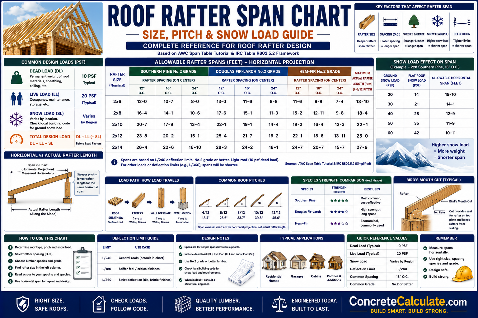
Roof Rafter Span Chart
Size, Pitch and Snow Load Guide
Complete roof rafter span reference for contractors and DIY builders, organized by rafter size, spacing, species/grade, roof pitch and snow load, following the AWC Span Table Tutorial and IRC framework.
 Reviewed by Muhammad Ramzan Babar, PhD Researcher (Plasma Physics) and Calculator Developer, View Profile
Important: Reference and Educational Guide Only
Rafter span depends on species, grade, spacing, snow load, dead load and deflection criteria together, not on rafter size alone. Values shown here illustrate the AWC Span Table Tutorial and IRC Table R802.5.2 framework using Southern Pine as a common reference species. These are illustrative figures, not a substitute for the applicable code table, your regional snow load, local amendments, or an engineer’s design. Always verify final rafter sizing against your local building code before construction.
⭐ Master Roof Rafter Span Chart
The primary table on this page, organized around rafter size, spacing, species/grade and roof load together, not a single misleading number per size.
Design Basis for This Table
Values below reflect Southern Pine, a 20 psf snow/live load plus 10 psf dead load basis, no ceiling attached (L/180 deflection), the common baseline used in IRC Table R802.5.2 and AWC’s Span Table Tutorial. All values are horizontal projection, not sloped rafter length. See the Horizontal Span vs Sloped Length section below for why this distinction matters.
| Rafter Size | 12 in OC | 16 in OC | 19.2 in OC | 24 in OC |
|---|---|---|---|---|
| 2×6 | 14′-4″ | 13′-0″ | 12′-2″ | 10′-8″ |
| 2×8 | 18′-11″ | 17′-2″ | 16′-1″ | 14′-0″ |
| 2×10 | 24′-2″ | 21′-11″ | 20′-6″ | 17′-10″ |
| 2×12 | 27′-11″ | 25′-4″ | 23′-9″ | 20′-9″ |
⭐ Roof Rafter Span by Rafter Size
Dedicated sections for each common dimensional size, at the Southern Pine, 20 psf snow load baseline described above.
| 2×6 Rafter | 12 in OC | 16 in OC | 19.2 in OC | 24 in OC |
|---|---|---|---|---|
| Southern Pine | 14′-4″ | 13′-0″ | 12′-2″ | 10′-8″ |
| 2×8 Rafter | 12 in OC | 16 in OC | 19.2 in OC | 24 in OC |
|---|---|---|---|---|
| Southern Pine | 18′-11″ | 17′-2″ | 16′-1″ | 14′-0″ |
| 2×10 Rafter | 12 in OC | 16 in OC | 19.2 in OC | 24 in OC |
|---|---|---|---|---|
| Southern Pine | 24′-2″ | 21′-11″ | 20′-6″ | 17′-10″ |
| 2×12 Rafter | 12 in OC | 16 in OC | 19.2 in OC | 24 in OC |
|---|---|---|---|---|
| Southern Pine | 27′-11″ | 25′-4″ | 23′-9″ | 20′-9″ |
| 2×14 Rafter | General Note |
|---|---|
| Solid-Sawn | Uncommon in dimensional lumber, long horizontal spans in this range typically use engineered lumber such as LVL instead, sized per manufacturer tables |
Increasing rafter depth generally increases both bending capacity and stiffness, since bending resistance grows with roughly the square of a member’s depth, subject to the applicable species, grade, spacing and load criteria used for that specific table.
⭐ Roof Rafter Span by Spacing
Comparing the four spacings AWC’s span resources account for when determining allowable rafter span.
| Spacing | Roof Load per Rafter | Effect on Span |
|---|---|---|
| 12 in OC | Lowest, more rafters share the load | Longest allowable span for a given size |
| 16 in OC | Moderate, common default | Standard span range, balances cost and performance |
| 19.2 in OC | Slightly higher | Slightly reduced span versus 16 in OC |
| 24 in OC | Highest, fewer rafters carry more each | Shortest allowable span for a given size |
Wider spacing widens the roof area each rafter must carry, which increases the load on that rafter and reduces its allowable span for the same size, species and grade.
⭐ Roof Rafter Span by Lumber Species
The same nominal rafter size can have different allowable spans depending on species and grade, since AWC’s methodology uses species-specific design values for E and Fb.
| Species Group | 2×10 Span (16 in OC, 20 psf snow load) | General Character |
|---|---|---|
| Southern Pine | 21′-11″ | Common baseline reference species in many published tables |
| Douglas Fir-Larch | 20′-8″ | Slightly reduced versus Southern Pine at this size and grade combination |
| Hem-Fir | 19′-8″ | Somewhat reduced compared to Southern Pine and Douglas Fir-Larch |
| Spruce-Pine-Fir | 19′-1″ | Generally the most conservative of the four common species groups at this size |
Never Assume a Universal Span Across Species
Allowable span depends on the specific combination of bending strength (Fb) and stiffness (E) for that exact species and grade, not on general reputation or a nearby species’ published value. Always use the design values that match your actual lumber.
Roof Rafter Span by Lumber Grade
Grade affects bending strength and stiffness, and therefore allowable span, even within the same species.
| Grade | Effect on Bending Strength | Effect on Stiffness | Effect on Allowable Span |
|---|---|---|---|
| Select Structural | Highest | Highest | Longest allowable span |
| No.1 | Higher than No.2 | Higher than No.2 | Slightly longer than No.2 |
| No.2 | Common baseline | Common baseline | Standard reference span used in most published tables |
| No.3 | Lower than No.2 | Lower than No.2 | Shorter allowable span |
⭐ Roof Rafter Span by Roof Load
Separating the loading conditions individually rather than combining them into one generic table.
| Load Type | Common Reference Range | Notes |
|---|---|---|
| Roof Live Load | 20 to 30 psf commonly referenced | Represents maintenance and light occupancy loads, code-dependent |
| Snow Load | Can range from roughly 20 to 60 psf or more, region-dependent | Treated as the governing live load in the rafter table for that region |
| Dead Load | 10 to 20 psf commonly referenced | Depends on the specific roof assembly weight |
| Combined Roof Loading | Sum of dead load plus the governing live or snow load | The actual design basis used to check the candidate rafter |
Loads Vary by Table and Region
AWC notes that rafter span tables are based on roof loads, with roof live or snow loads commonly ranging from 20 to 60 psf and roof dead loads ranging from 10 to 20 psf, depending on the applicable table and design condition. The actual governing values must come from your local code, not a generic assumption.
Roof Dead Load Chart
Permanent roof weight that reduces allowable rafter span as it increases.
| Component | Contributes to Dead Load |
|---|---|
| Roof Sheathing | Structural panel weight covering the rafters |
| Roofing Material | Varies significantly by material, see the roofing material comparison below |
| Underlayment | Small but real contribution beneath the roofing material |
| Insulation | Adds weight when installed at or above the roof deck |
| Ceiling Materials | Drywall or other finishes attached to the underside of the rafters |
| Rafters | Self-weight of the framing lumber itself |
| Mechanical/Electrical Components | Ductwork, wiring and fixtures supported within the roof assembly |
| Solar Equipment (where applicable) | Adds concentrated dead load, see the dedicated solar section below |
Roof Live Load Chart
Roof live load should not automatically be treated as ordinary floor live load.
| Concept | Explanation |
|---|---|
| Roof Live Load | Represents temporary loads such as maintenance workers and equipment, generally lighter than floor occupancy loads |
| Maintenance Loads | Anticipates occasional foot traffic and light equipment for repairs or inspections |
| Occupancy Limitations | Roofs are generally not designed for regular human occupancy the way floors are |
| Code-Specific Requirements | The actual governing roof live load value comes from your local code, not a generic residential assumption |
⭐ Roof Snow Load Chart
A major section, since snow load frequently governs rafter sizing in cold climates and varies dramatically by location.
| Concept | Explanation |
|---|---|
| Ground Snow Load | The baseline regional value found in your code book, varies widely across climate zones |
| Roof Snow Load | Derived from ground snow load with adjustments for roof geometry and exposure |
| Balanced Snow | Assumes snow accumulates roughly evenly across the roof surface |
| Unbalanced Snow | Accounts for wind-driven redistribution that can pile more snow on one side of a roof |
| Snow Accumulation | Depth and density both affect the actual load, not just presence of snow |
| Snow Drifting | Can create locally concentrated loads beyond a simple uniform assumption |
| Local Climatic Conditions | Elevation, latitude and microclimate all influence the applicable snow load |
Determine Snow Load First, Before Selecting a Table
AWC explains that its span calculator requires the designer to determine the applicable roof snow load first, since the calculator itself does not perform the ASCE 7 snow-load adjustments for balanced versus unbalanced conditions. You must determine the snow load for your region from your code book, then use it as the live load value when selecting the correct rafter table. If your code book specifies a 40 psf snow load, you use the 40 psf live load rafter table, not a generic default.
⭐ Roof Rafter Span and Roof Pitch
Common pitch categories and the critical distinction that governs how rafter tables actually work.
| Pitch | Rise per 12 in Run | General Character |
|---|---|---|
| 2:12 | 2 inches | Very low slope, near-flat roof category |
| 3:12 | 3 inches | Low slope, the threshold for the L/180 deflection provision |
| 4:12 | 4 inches | Common moderate slope |
| 5:12 | 5 inches | Common residential pitch |
| 6:12 | 6 inches | Common residential pitch |
| 8:12 | 8 inches | Steeper residential pitch |
| 10:12 | 10 inches | Steep pitch |
| 12:12 | 12 inches | 45 degree pitch, quite steep |
Pitch Does Not Change the Table Value
Rafter span tables report horizontal projection, not the sloped rafter length, so changing roof pitch alone does not change the span value you read from a table. What pitch does change is the physical rafter length needed to cover that same horizontal span, and it also affects the deflection provision, since AWC’s tables commonly apply L/240 for rafters with slopes greater than 3:12 with a finished ceiling attached, and L/180 for rafters with no finished ceiling attached.
⭐ Horizontal Rafter Span vs Sloped Rafter Length
The single most important distinction on this page and one of the most common user mistakes in roof framing.
| Measurement | What It Represents | Used For |
|---|---|---|
| Horizontal Projection | The horizontal distance from the inside surface of the supporting wall to the inside surface of the ridge board | The span value used in every published rafter span table |
| Sloped Rafter Length | The actual physical measurement along the rafter from the wall bearing point to the ridge | Determining the physical lumber length needed to cut and install |
AWC’s Own Example
AWC’s Span Table Tutorial explicitly states that the span of a rafter is not based on the measurement along its length, but on the rafter’s horizontal projection, defined as the horizontal distance from the inside surface of the supporting wall to the inside surface of the ridge board. AWC gives a worked example: for a simple gable roof on a 24-foot wide ranch framed with 2×6 exterior walls and a 1½ inch ridge, the span used for the rafter table is 11 feet 5¾ inches, not the actual sloped length of the rafter, which is always longer once pitch is applied. If you look up your rafter’s physical cut length in a span table, you will get an incorrect and overly conservative result.
⭐ Roof Rafter Span and Deflection
Two distinct deflection limits apply to rafters, depending on whether a ceiling is attached below.
| Deflection Limit | When It Applies |
|---|---|
| L/180 | Rafters having slopes greater than 3:12 with no finished ceiling attached to the rafters |
| L/240 | Rafters with a finished ceiling attached to the underside, such as cathedral ceilings, where the ceiling attachment makes deflection more restrictive |
Why the Ceiling Attachment Matters
AWC specifically identifies L/240 and L/180 as rafter deflection limitations, with L/240 allowing for ceiling attachment and L/180 applicable where there is no ceiling directly attached. The reasoning is that a finished ceiling surface, such as drywall, will crack more readily under the same amount of bending than exposed rafters would, so the stricter L/240 limit protects that finish. A rafter without a ceiling attached is allowed slightly more deflection since there is no brittle finish at risk.
Roof Rafter Span and Bending Strength
The bending design value used alongside other checks to determine allowable rafter span.
What Fb Represents
Fb is the bending design value, representing the allowable extreme fiber stress in bending for a given species and grade, measured in pounds per square inch. AWC’s span methodology uses the bending design value together with other checks to determine allowable rafter span. Rafter depth, species and grade all directly influence the available Fb, which is why a deeper rafter or a higher grade generally supports a longer span before the bending check governs.
Roof Rafter Span and Modulus of Elasticity
Why two rafters with similar bending strength can still have different allowable spans.
What E Means for a Rafter
Modulus of elasticity (E) measures a wood member’s stiffness, or its resistance to bending under load. Higher E values mean a stiffer rafter that deflects less under the same load, allowing a longer span before hitting the applicable deflection limit. AWC’s span calculator uses E, Fb and Fv together in its span calculations, which is why two species with similar bending strength can still produce different published rafter spans if their stiffness values differ.
⭐ Roof Rafter Span and Shear
An often overlooked check that can become important on shorter, heavily loaded spans.
| Concept | Explanation |
|---|---|
| Shear Forces | Internal forces acting perpendicular to the rafter’s length, highest near the supports |
| Rafter Reactions | The forces transferred at the wall and ridge support points |
| End Support | Where shear stress concentrates and must be checked against the shear design value (Fv) |
| Why Shear Matters for Short Spans | Shorter, heavily loaded rafters can hit their shear limit before bending or deflection becomes the governing check |
AWC’s calculator methodology includes shear strength as one of the governing span checks, alongside bending, deflection and bearing, which is why a published span always reflects whichever of these checks is most restrictive for that specific size, species, grade and load combination.
⭐ Roof Rafter Bearing Requirements
The final check in the rafter selection process, since roof load transfers through the rafter ends into the supporting wall.
| Requirement | Explanation |
|---|---|
| Wall Bearing | The rafter must rest on the wall top plate with adequate bearing area |
| Ridge Support | Opposing rafters bear against each other or a ridge member at the peak |
| Birdsmouth Bearing | A notch cut into the rafter to create a flat seat on the wall plate, discussed in detail below |
| Compression Perpendicular to Grain | The bearing check that verifies the wood does not crush under the concentrated reaction force |
| Required Bearing Length | Determined from the reaction force divided by the allowable compression perpendicular to grain stress |
AWC’s span calculation guidance specifically uses compression perpendicular to grain (Fcp) to determine the minimum required bearing length at rafter ends. Verify bearing capacity with our Load Bearing Calculator.
Roof Rafter Span and Ridge Board
A ridge board is not the same structural system as a ridge beam, a distinction that matters for load path.
| Concept | Explanation |
|---|---|
| Ridge Board | A nonstructural board providing a nailing surface where opposing rafter pairs meet |
| Rafter Support | The ridge board does not carry roof load down to the ground, the opposing rafters support each other |
| Opposing Rafters | Rafter pairs on either side of the ridge that lean against each other and the ridge board |
| Ridge Connection | Typically a simple nailed connection, since the ridge board itself carries minimal load |
| Ridge Board vs Ridge Beam | See the dedicated comparison section immediately below |
⭐ Roof Rafter Span and Ridge Beam
A structural ridge beam changes the roof load path entirely compared to a simple ridge board.
| Factor | Ridge Board | Structural Ridge Beam |
|---|---|---|
| Structural Role | Nonstructural, provides only a nailing surface | Actively carries roof load, structurally required |
| Support Requirement | Relies on opposing rafters and rafter ties | Requires its own posts and foundation support |
| Common Applications | Standard gable roofs with rafter ties present | Cathedral ceilings or open floor plans without rafter ties |
| Load Path Impact | Load resolves through the rafter pair and tie system | Load transfers directly down through the beam to posts and foundation |
⭐ Roof Rafter Span and Rafter Ties
Rafter ties, ceiling joists and collar ties serve distinct structural roles and should not be treated as interchangeable.
| Concept | Explanation |
|---|---|
| Rafter Ties | Members near the wall plate resisting outward spreading forces from the rafters |
| Ceiling Joists | Often serve double duty as rafter ties when positioned low, near the wall plate |
| Collar Ties | Positioned higher, primarily resisting uplift and separation rather than gravity spreading |
| Structural Role | Each member resists a different force, so substituting one for another can leave a gap in the load path |
| Location | Rafter ties near the plate, collar ties in the upper third of the roof, positioning is not interchangeable |
Rafter Ties vs Collar Ties
A dedicated comparison targeting a strong informational search intent.
| Feature | Rafter Tie | Collar Tie |
|---|---|---|
| Location | Low, near the wall plate | High, in the upper third of the roof |
| Main Purpose | Resists outward spreading of the rafters under gravity load | Resists wind uplift and rafter separation |
| Structural Function | Primary gravity load path member, often doubles as a ceiling joist | Secondary member, generally not load-bearing under normal gravity conditions |
| Typical Placement | At or near ceiling joist level | Above the midpoint of the rafter length, closer to the ridge |
Roof Rafter Span and Ceiling Joists
How the complete roof framing system transfers loads through connected members.
Rafters, Ceiling Joists and Rafter Ties Working Together
In a standard gable roof, rafters carry roof load down to the wall, while ceiling joists positioned at the same level as the wall plate often serve simultaneously as rafter ties, resisting the outward thrust that rafters naturally exert. This combined system allows the roof to be self-supporting without a structural ridge beam, provided the tie connection and rafter-to-wall connection are both properly detailed.
Roof Rafter Cantilever / Overhang Chart
Clearly distinguishing rafter span from rafter overhang.
| Concept | Explanation |
|---|---|
| Rafter Overhang | The portion of the rafter extending past the wall, unsupported below |
| Eave Projection | Another common term for the overhang distance, measured horizontally |
| Birdsmouth | The notch where the rafter bears on the wall plate, separating the interior span from the tail |
| Wall Plate | The bearing point where the rafter transitions from interior span to overhang |
| Tail | The cantilevered portion of the rafter beyond the birdsmouth |
| Cantilever | The general structural term for the unsupported overhang condition |
⭐ Roof Rafter Birdsmouth Cut
The notch that creates a flat bearing surface where the rafter meets the wall plate.
| Element | Explanation |
|---|---|
| Birdsmouth Purpose | Creates a flat, stable bearing surface where an angled rafter meets a horizontal wall plate |
| Seat Cut | The horizontal cut that rests flat on the wall plate |
| Plumb Cut | The vertical cut that forms the inner face of the notch |
| Bearing | The seat cut surface must provide adequate bearing length per the compression perpendicular to grain check |
| Maximum Cutting Considerations | Notching too deep reduces the remaining rafter depth at a critical stress location, weakening the member |
Roof Rafter Notching and Drilling
Where cutting into a rafter is permitted, and why excessive cutting weakens the member.
| Location | General Guidance |
|---|---|
| Notches | The birdsmouth at the bearing point is an accepted, standard notch, additional mid-span notching is generally restricted |
| Holes | Generally permitted only within a defined zone near the neutral axis, away from supports |
| Cutting Restrictions | Maximum notch and hole limitations vary by rafter depth and applicable code |
| Strength Reduction | Removing material where bending stress is highest seriously reduces capacity |
| Location of Cuts | Always check the specific limit for your rafter depth rather than guessing |
Roof Rafter Span Around Roof Openings
Framing around roof penetrations requires additional supporting members beyond standard rafter spacing.
| Opening Type | Framing Requirement |
|---|---|
| Skylights | Header and trimmer rafters frame the opening, often doubled for added capacity |
| Chimneys | Requires framed clearance and fire-rated separation in addition to structural framing |
| Attic Access | Smaller opening, typically needs only local header and trimmer framing |
| Roof Vents | Small penetrations may need only minor local reinforcement depending on size |
| Dormers | Substantial framing change, often requiring double rafters and dedicated headers at the dormer sides |
| Large Penetrations | Require header and trimmer framing similar to skylights, scaled to the opening size |
Equipment for Your Project
Affiliate disclosure: As an Amazon Associate, ConcreteCalculate earns from qualifying purchases. We may also earn a commission from other affiliate links at no additional cost to you.
Roof Rafter Span for Different Roof Types
Roof geometry changes the framing arrangement and load path significantly.
| Roof Type | General Framing Character |
|---|---|
| Gable Roof | Two sloped planes meeting at a ridge, common rafters throughout |
| Hip Roof | Four sloped planes, requiring hip and jack rafters in addition to common rafters |
| Shed Roof | Single sloped plane, one high wall and one low wall |
| Gambrel Roof | Two slopes per side at different pitches, more complex framing |
| Saltbox Roof | Asymmetric gable with one longer slope than the other |
| Mansard Roof | Four-sided roof with two slopes per side, complex framing throughout |
Roof Rafter Span for Gable Roofs
The most common residential roof configuration.
| Element | Role |
|---|---|
| Ridge | The peak where opposing rafter pairs meet |
| Opposing Rafters | Common rafters framing each of the two roof planes |
| Rafter Ties | Resist the outward spreading force at the wall plate level |
| Gable-End Framing | Vertical wall framing at each gable end, distinct from the sloped rafters |
Roof Rafter Span for Hip Roofs
Hip roofs introduce specialized rafter types beyond ordinary common rafters.
| Element | Role |
|---|---|
| Hip Rafters | Run diagonally from the corner of the building to the ridge, carrying jack rafter loads |
| Jack Rafters | Shorter rafters running from the wall plate to a hip or valley rafter rather than the ridge |
| Ridge | Shorter than in a comparable gable roof, since the hips converge before reaching the building ends |
| Valley/Hip Geometry | Creates compound angles that complicate both cutting and load calculation |
Common Rafter Tables Do Not Directly Size Every Member
Ordinary common-rafter span tables may not directly size hip rafters, jack rafters, or valley rafters, since these members carry different load patterns and geometry than a straightforward common rafter. Specialized calculations or engineered design are often needed for these specific members.
Roof Rafter Span for Shed Roofs
A single-slope roof configuration with distinct bearing conditions at each wall.
| Element | Explanation |
|---|---|
| Single-Slope Roof | One continuous plane running from the high wall to the low wall |
| High Wall | Bears the upper end of the rafters |
| Low Wall | Bears the lower end of the rafters |
| Rafter Bearing | Occurs at both walls, similar in principle to a standard rafter but without a ridge condition |
| Horizontal Projection | Still measured horizontally between the two wall bearing points, following the same principle as any other rafter |
Roof Rafter Span for Cathedral Ceilings
Exposed sloped ceilings connect directly to the L/240 deflection provision discussed above.
| Consideration | Explanation |
|---|---|
| Rafter Deflection | Governed by the L/240 limit since a finished ceiling is attached directly to the rafters |
| Ceiling Attachment | The drywall or other finish attached to the underside changes the applicable deflection criteria |
| Rafter Ties | Often absent or relocated in cathedral ceiling designs, requiring an alternative load path |
| Ridge Beam Considerations | Cathedral ceilings frequently require a structural ridge beam rather than a simple ridge board, since rafter ties are typically not present at the usual location |
Roof Rafter Span for Attics
Attic classification changes the load basis significantly, so a single rafter table should not apply automatically.
| Attic Classification | Load Character |
|---|---|
| Uninhabitable Attic | Lightest load category, typically dead load only with minimal live load provision |
| Attic Storage | Adds a limited storage live load beyond the uninhabitable basis |
| Habitable Attic | Requires standard residential floor live load provisions where a floor is created |
Roof Rafter Span for Solar Panels
Solar installations introduce additional structural and attachment requirements beyond a standard roof-span table.
| Additional Load Source | Consideration |
|---|---|
| Solar Panels | Adds distributed dead load across the mounted area |
| Mounting Rails | Concentrates load at specific attachment points along the rafters |
| Attachment Hardware | Requires structural connection back into the rafters, not just the roof sheathing |
Roof Rafter Span for Heavy Roofing
Heavier roofing materials directly increase dead load, reducing allowable rafter span.
| Material | Relative Weight Character |
|---|---|
| Asphalt Shingles | Common lighter-weight baseline material |
| Metal Roofing | Often lighter than asphalt shingles per square foot in many products |
| Wood Shakes | Generally heavier than asphalt shingles |
| Clay/Concrete Tile | Substantially heavier than asphalt shingles, often requiring reinforced framing |
| Slate | Among the heaviest common roofing materials, frequently requiring engineered rafter design |
Roof Rafter Span for Different Roofing Materials
A practical comparison of relative dead load impact, without assigning unsourced universal weight values.
| Roofing Material | Relative Dead Load | Structural Consideration |
|---|---|---|
| Asphalt Shingles | Light to moderate | Fits within standard residential dead load assumptions |
| Metal Roofing | Light | Often reduces dead load compared to shingles, though panel and fastening details vary |
| Wood Shakes | Moderate | May approach or exceed standard dead load assumptions depending on thickness |
| Clay/Concrete Tile | Heavy | Frequently requires increased rafter size or spacing adjustment and specific manufacturer guidance |
| Slate | Very heavy | Often requires engineered structural design beyond standard prescriptive tables |
Always confirm actual roofing product weight with the manufacturer, since weight varies meaningfully within each material category depending on thickness, profile and installation method.
⭐ Roof Rafter Span for Engineered Lumber
Engineered products should be designed using manufacturer-specific span tables and design values.
| Product | General Note |
|---|---|
| LVL (Laminated Veneer Lumber) | Can achieve longer horizontal spans than dimensional lumber at the same depth, requires manufacturer span data |
| Glulam | Common for structural ridge beams and long-span rafters, carries its own stated design assumptions |
| I-Joists | Sometimes used as rafters in specific applications, sized entirely by manufacturer-published tables |
| Engineered Rafters (general) | Any manufactured rafter product must be designed to its own certified span and load data |
Never Treat Engineered Lumber Like Dimensional Lumber
Engineered products are manufactured to different, product-specific design values and are not interchangeable with sawn-lumber span tables. Always use the manufacturer’s published span data for the exact product being installed.
Solid-Sawn Rafters vs Engineered Rafters
A general comparison of the two main rafter categories.
| Factor | Solid-Sawn | Engineered |
|---|---|---|
| Span | Moderate, governed by species and grade design values | Generally longer for a given depth, per manufacturer tables |
| Weight | Heavier per linear foot for comparable span capacity | Often lighter per linear foot for comparable span capacity |
| Stability | Can twist, warp or shrink with moisture changes | More dimensionally stable |
| Availability | Widely available at most lumber yards | May require special order or lead time depending on size |
| Openings | Limited notching and drilling zones | Varies by product, some allow flexible openings |
| Installation | Familiar to most framers | Requires manufacturer-specific hardware and guidance |
| Cost | Generally lower material cost | Generally higher material cost |
⭐ Roof Rafter Span and Wind Load
Wind introduces forces that ordinary gravity span tables do not address on their own.
| Concept | Explanation |
|---|---|
| Wind Pressure | Lateral force from wind acting on the roof surface and framing |
| Uplift | Wind can create a suction effect that lifts the roof upward rather than pushing it down |
| Rafter-to-Wall Connections | Must resist uplift forces, not just gravity bearing |
| Hurricane Ties | Metal connectors specifically designed to resist uplift at the rafter-to-wall connection |
| Roof-to-Wall Load Path | The complete connection chain that must transfer wind forces safely into the wall and foundation |
The current Wood Frame Construction Manual covers roof systems and includes provisions for connections and wind-related structural requirements, since gravity span tables alone do not address uplift or lateral wind forces.
Roof Rafter Span and Wind Uplift
Uplift reverses the normal direction of the roof load path, requiring its own connection design.
How Uplift Differs from Gravity Loading
Under normal gravity loading, the load path runs from roof covering to sheathing to rafters to wall to foundation, with each member pressing down on the one below it. Wind uplift reverses this direction, trying to pull the roof covering away from the sheathing, the sheathing away from the rafters, and the rafters away from the wall. This is why uplift connections, such as hurricane ties, are a completely separate design check from the gravity span calculation covered in the rest of this page, since a rafter sized correctly for gravity load can still fail in an uplift event if its connections are inadequate.
Roof Rafter Span for High-Wind Areas
General concepts only, never a single connector or fastening pattern presented as universal.
| Consideration | General Note |
|---|---|
| Uplift Connectors | Rated for specific load capacities that must match the calculated uplift force for the location |
| Rafter-to-Wall Connections | Connection type and capacity vary significantly by local wind speed requirements |
| Sheathing Fastening | Nail spacing and fastener type often become more restrictive in high-wind zones |
| Local Wind Speed | The design basic wind speed for your specific location drives every connection requirement |
| Code Requirements | High-wind provisions are jurisdiction-specific and must be verified locally, not assumed |
⭐ Roof Rafter Span and Unbalanced Snow Load
A design condition that standard span calculators do not automatically account for.
The Designer Must Determine This, Not the Calculator
AWC explicitly notes that its span calculator does not calculate ASCE 7 snow-load adjustments for balanced versus unbalanced conditions automatically. The designer must determine the appropriate snow condition, including any unbalanced or drifting adjustment required by the applicable wind and snow provisions, and input the resulting roof snow load into the span table selection process. A roof with significant slope change, adjacent taller structures, or valley conditions is particularly prone to unbalanced snow accumulation, and this should be evaluated separately before selecting a rafter size.
⭐ Roof Rafter Load Path
One of the main visual assets on this page, showing the complete journey of roof load down to the foundation.
⭐ Visual Roof Rafter Span Guide
Original engineering diagrams designed to be useful for contractors, students and DIY builders alike.
4:12
Moderate pitch6:12
Common residential8:12
Steeper pitch12:12
45 degree pitchSee also the horizontal span versus sloped length diagram, birdsmouth diagram, ridge board versus ridge beam comparison, rafter tie versus collar tie diagram, cantilever diagram and snow load diagram presented earlier in their dedicated sections above.
⭐ How to Read a Roof Rafter Span Table
Following the same workflow AWC recommends when selecting a rafter from its published span tables.
Rafter Size
Confirm the nominal dimensional size matches your framing plan.
Species
Verify the table matches your actual lumber species, values do not transfer between species.
Grade
Check whether the table assumes No.2, No.1 or Select Structural grade.
Spacing
Find the on-center spacing column matching your actual layout.
Roof Pitch
Confirm the deflection provision that applies, since pitch determines whether L/180 or L/240 governs.
Roof Live/Snow Load
Determine your applicable snow load first, then select the table built around that value.
Dead Load
Confirm the roof assembly weight assumption matches your actual construction.
Deflection Limit
Confirm whether a ceiling is attached, which determines the L/180 versus L/240 provision.
Horizontal Projected Span
Read the resulting maximum horizontal span, not the sloped rafter length.
Required E and Fb
Confirm the modulus of elasticity and bending design value used match your species and grade.
Bearing Requirements
Confirm the minimum bearing length assumed at the wall and ridge.
⭐ How to Calculate Roof Rafter Span
A practical workflow that closely follows the actual AWC span-selection methodology.
Determine Roof Geometry
Identify the roof type, pitch and overall dimensions of the structure.
Determine Horizontal Projected Span
Measure the horizontal distance from the inside face of the wall to the inside face of the ridge, not the sloped rafter length.
Determine Rafter Spacing
Choose an on-center spacing that fits your roof sheathing requirements.
Determine Roof Dead Load
Confirm the actual roof assembly weight, including roofing material, sheathing and any ceiling finish.
Determine Roof Live Load or Snow Load
Confirm your applicable ground snow load and any regional adjustments before selecting a table.
Determine Applicable Deflection Limit
Confirm whether a finished ceiling is attached, which determines L/180 versus L/240.
Select Species and Grade
Confirm what lumber will actually be used, not assumed.
Check Allowable Span
Verify the candidate rafter’s allowable horizontal span meets your required design span.
Check Bending
Confirm adequate strength margin under the applied roof loads.
Check Shear
Verify the rafter resists internal shear forces near its supports.
Check Deflection
Verify the rafter stays within the applicable deflection limit under load.
Check Bearing
Confirm adequate bearing length at the wall and ridge connections.
Check Connections and Uplift
Verify wind uplift connectors and fastening meet your local wind requirements.
⭐ Roof Rafter Span Worked Examples
Realistic scenarios illustrating how size, spacing, pitch, species and snow load interact.
12-Foot Horizontal Span
16-Foot Horizontal Span
Changing Rafter Spacing
Changing Roof Pitch
Snow-Load Location
Ceiling Attached vs No Ceiling
Common Roof Rafter Sizing Mistakes
Avoiding these errors prevents undersized rafters, sagging roofs and code violations.
Using Actual Rafter Length as the Span
Published tables use horizontal projection, not the sloped physical length of the rafter.
Ignoring Horizontal Projection
Confusing horizontal span with sloped length can lead to selecting an undersized rafter that appears adequate on paper.
Ignoring Snow Load
Assuming a snow-free load basis in a region with significant snowfall can seriously undersize the rafters.
Using Floor-Joist Tables for Rafters
Floor joist tables use different load assumptions and deflection limits than rafter-specific tables.
Ignoring Roof Pitch
Pitch determines which deflection provision applies and affects the physical rafter length needed.
Ignoring Rafter Spacing
Applying a 16 inch OC span value to a 24 inch OC layout overstates the rafter’s actual capacity.
Ignoring Species
Assuming all lumber species perform identically ignores real differences in bending strength and stiffness.
Ignoring Grade
A lower grade board does not carry the same allowable span as a higher grade board of the same species and size.
Ignoring Dead Load
Heavier roofing materials like tile or slate reduce allowable span compared to a lighter assumption.
Ignoring Deflection
A rafter that will not break can still sag more than the applicable L/180 or L/240 limit allows.
Confusing Ridge Board with Ridge Beam
A nonstructural ridge board cannot be substituted for a structural ridge beam without changing the load path and adding proper support.
Confusing Rafter Ties with Collar Ties
These members resist different forces at different locations and are not interchangeable.
Over-Cutting Birdsmouths
Cutting the notch too deep reduces the remaining rafter depth at a critical stress location.
Ignoring Bearing
Insufficient bearing length at the wall or ridge can compromise an otherwise correctly sized rafter.
Ignoring Wind Uplift
A rafter sized correctly for gravity load can still fail in a wind event if its connections are inadequate.
Using Ordinary Tables for Solar Installations Without Checking Added Loads
Solar panels and mounting hardware add dead load and concentrated attachment forces beyond a standard roof span table.
Frequently Asked Questions
📄 Download Roof Rafter Span Chart PDF
Get a printable reference including master rafter span tables, 2×6 to 2×12 comparison, rafter spacing chart, species/grade guide, roof load guide, snow-load guide, deflection guide, horizontal span diagram, roof pitch diagram, birdsmouth diagram, ridge board versus ridge beam diagram, rafter tie versus collar tie diagram, worked examples and a contractor quick-reference sheet.