Header Span Chart 2026 – Size by Opening, Plies and Load
Header Span Chart
Size by Opening, Plies and Load
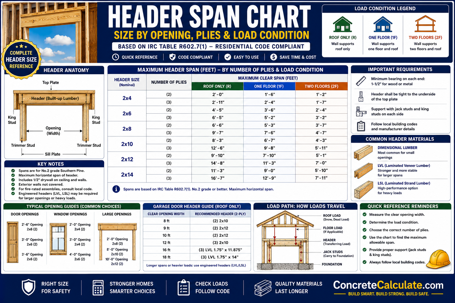
Complete header sizing reference for contractors and DIY builders, organized by opening width, number of plies and load condition, since a header supporting only a roof is a completely different structural situation from one supporting a floor and roof.
 Reviewed by Muhammad Ramzan Babar, PhD Researcher (Plasma Physics) and Calculator Developer, View Profile
Important: Reference and Educational Guide Only
Header size cannot be selected from opening width alone. The load condition above the header, whether it is roof only, one floor plus roof, or two floors plus roof, changes the required header size dramatically at the exact same opening width. Values shown here illustrate the IRC Table R602.7(1) framework using a 30 psf ground snow load and number 2 grade lumber as a common reference basis. These are illustrative figures, not a substitute for the applicable code table, your regional snow load, local amendments, or an engineer’s design. Always verify final header sizing against your local building code before construction.
⭐ Master Header Span Chart
The primary table on this page, organized around header size, plies, opening width and load condition together, since load condition changes the answer dramatically at the same opening width.
Design Basis for This Table
Values below reflect number 2 grade Southern Pine or Douglas Fir-Larch, a 30 psf ground snow load basis, and standard IRC Table R602.7(1) load conditions. These are illustrative figures, not a substitute for your specific applicable table and local snow load.
| Header Size (Plies) | Roof Only | One Floor + Roof | Two Floors + Roof |
|---|---|---|---|
| 2-ply 2×6 | 4′-6″ | 3′-6″ | 2′-6″ |
| 2-ply 2×8 | 5′-9″ | 4′-6″ | 3′-2″ |
| 2-ply 2×10 | 6′-10″ | 5′-4″ | 3′-9″ |
| 2-ply 2×12 | 8′-1″ | 6′-4″ | 4′-5″ |
| 3-ply 2×10 | 8′-5″ | 6′-7″ | 4′-8″ |
| 3-ply 2×12 | 9′-11″ | 7′-9″ | 5′-6″ |
⭐ Header Span by Header Size
Dedicated sections for each common dimensional size, showing how depth and configuration together affect capacity.
| 2×4 Header | General Note |
|---|---|
| Double 2×4 | Common only for very light, non-load-bearing partition openings up to roughly 3 feet |
| 2×6 Header | Roof Only | One Floor + Roof |
|---|---|---|
| Double 2×6 | 4′-6″ | 3′-6″ |
| 2×8 Header | Roof Only | One Floor + Roof |
|---|---|---|
| Double 2×8 | 5′-9″ | 4′-6″ |
| 2×10 Header | Roof Only | One Floor + Roof |
|---|---|---|
| Double 2×10 | 6′-10″ | 5′-4″ |
| 2×12 Header | Roof Only | One Floor + Roof |
|---|---|---|
| Double 2×12 | 8′-1″ | 6′-4″ |
| 2×14 / 2×16 Header | General Note |
|---|---|
| Solid-Sawn | Uncommon in dimensional lumber, wide openings in this range typically use engineered LVL or PSL instead, sized per manufacturer tables |
⭐ Header Span by Number of Plies
Adding plies increases capacity, but not in a simple multiple, and requires proper fastening between plies to actually work together.
| Configuration | 2×10 Span (roof only) | General Note |
|---|---|---|
| Single 2x Header | Not typically used structurally alone | A single ply lacks adequate width for most load-bearing applications |
| Double 2x Header | 6′-10″ | Most common configuration for standard residential openings |
| Triple 2x Header | 8′-5″ | Used for wider openings or heavier load conditions |
| Built-Up (4+ plies) | Varies by design | Requires engineering verification and proper connector hardware between plies |
Three Plies Does Not Mean Three Times the Span
Notice that going from double to triple 2×10 only increases allowable span from 6′-10″ to 8′-5″, not to three times the double-ply value. Adding plies increases the effective width of the header and therefore its capacity, but the relationship is not linear, and it also depends on the plies being properly fastened together so they act as one unit and share load, rather than acting as separate, independently loaded boards.
⭐ Header Span by Opening Width
A practical reference by common opening width, clarifying the distinction between rough opening and header span.
| Opening Width | Roof Only (typical) | One Floor + Roof (typical) |
|---|---|---|
| 2 ft | Double 2×4 to 2×6 | Double 2×6 |
| 3 ft | Double 2×6 | Double 2×6 to 2×8 |
| 4 ft | Double 2×6 | Double 2×8 |
| 5 ft | Double 2×8 | Double 2×8 to 2×10 |
| 6 ft | Double 2×8 | Double 2×10 |
| 7 ft | Double 2×8 to 2×10 | Double 2×10 |
| 8 ft | Double 2×10 | Triple 2×10 or double 2×12 |
| 10 ft | Triple 2×10 | Engineered LVL typical |
| 12 ft | Triple 2×12 | Engineered LVL required |
| 14 ft | Engineered LVL typical | Engineered LVL required |
| 16 ft | Engineered LVL required | Engineered LVL required |
Rough Opening Width vs Header Span
Rough opening width is the framed gap sized to fit the door or window unit, typically 2 to 3 inches wider than the actual door or window itself. Header span, or the supported opening, is the distance the header must structurally clear between its jack stud bearing points, which is essentially the same as the rough opening width but is the actual structural design value used when consulting a header table.
⭐ Header Span by Wall Type
A header over an opening in a non-load-bearing partition can have dramatically different requirements than one supporting floors or a roof.
| Wall Type | Typical Load | Header Consideration |
|---|---|---|
| Exterior Load-Bearing Wall | Roof and possibly floor loads | Requires full structural header sized to the load condition above |
| Interior Load-Bearing Wall | Floor and possibly roof loads from above | Requires full structural header, often carrying significant tributary load |
| Non-Load-Bearing Partition | Only the wall material itself, no floor or roof load | Lighter framing member adequate, structural header table generally not needed |
⭐ Header Span by Load Condition
One of the most important sections on this page. Header size cannot be selected from opening width alone.
| Load Condition | What It Represents | Effect on Header Demand |
|---|---|---|
| Roof-Only Load | Single-story building or top-floor interior wall, only roof bears above | Lightest common load condition |
| One-Floor Load | Wall on the ground floor of a two-story building, one floor plus roof above | Moderately increased demand versus roof-only |
| Two-Floor Load | Wall on the ground floor of a three-story building, two floors plus roof above | Substantially increased demand |
| Floor + Roof Load | General term covering any wall with both floor and roof load above it | Higher than roof-only, varies by number of floors |
| Attic Load | Additional live load if the attic above is used for storage or is habitable | Adds to whatever the base roof load condition already requires |
| Multiple-Story Load | Any condition with more than one floor level bearing above the header | Highest common demand for standard residential headers |
Identify the Design Condition Before Selecting a Member
Wood design methodology emphasizes identifying the actual design load and structural condition before selecting a member, rather than jumping straight to a header size based on opening width. The same 8-foot opening can require a double 2×10, a triple 2×10, or an engineered LVL, depending entirely on whether it is roof-only, one floor plus roof, or two floors plus roof.
⭐ Header Load Chart
The complete load path showing how structure above an opening transfers down through the header.
The amount of structure above an opening directly sets the tributary load reaching the header. A header centered under a large roof area, or beneath multiple floors, receives proportionally more load than the same size opening under a small roof section alone.
⭐ Header Tributary Area Chart
One of the strongest original graphics on this page, showing how the structure above an opening translates into header load.
Header Span for Roof Loads
Roof configuration significantly affects the load reaching a header, even in a single-story building.
| Roof Element | Effect on Header |
|---|---|
| Roof Rafters | Deliver load based on rafter span and spacing directly to the wall |
| Roof Trusses | Can deliver concentrated point loads at bearing points rather than uniform load, see the trusses section below |
| Attic Loads | Add to the base roof dead and live load if the attic is used for storage |
| Snow Loads | Can substantially increase roof load in cold climate regions |
| Roof Dead Loads | Varies by roofing material weight, heavier materials increase header demand |
Header Span for Floor Loads
Floor loads above an opening reach the header through the wall framing above.
| Element | Explanation |
|---|---|
| First-Floor Headers | Openings on the ground floor of a multi-story building often support one or more floors above |
| Second-Floor Headers | Openings on an upper floor typically support only the roof above, a lighter load condition |
| Floor Joists Framing Toward the Wall | Deliver their tributary load into the wall directly above the header |
| Floor Loads Above the Opening | Transfer down through the wall studs on either side of the header into the header itself |
⭐ Header Span for Multiple Floors
Increasing the number of supported levels generally increases header demand substantially.
| Condition | Relative Demand | Typical Impact |
|---|---|---|
| One Story Above (roof only) | Lowest | Baseline condition, longest allowable header spans |
| Two Stories Above (one floor + roof) | Moderate | Noticeably reduced allowable span for the same header size |
| Multiple Floors + Roof (two floors + roof) | Highest common condition | Substantially reduced allowable span, often requires engineered members even at moderate opening widths |
⭐ Header Span and Snow Load
Snow load varies dramatically by region, there is no single universal snow load for every location.
| Concept | Explanation |
|---|---|
| Ground Snow Load | Regional baseline value found in your local code book, varies from near zero to 70 psf or more across different published provisions |
| Roof Snow Load | Derived from ground snow load with adjustments for roof geometry and exposure |
| Snow Accumulation | Depth and density both affect the actual load transferred through the roof to the header |
| Local Climate | Elevation, latitude and microclimate all influence the applicable value for your specific site |
| Unbalanced Snow (where applicable) | Wind-driven redistribution that can create concentrated loading on one side of certain roof shapes |
Ground Snow Loads Vary Widely
The current Wood Frame Construction Manual uses ASCE 7-22-based design provisions and covers ground snow loads ranging from 0 to 70 psf in its tabulated provisions, reflecting how dramatically snow load varies by region. Always confirm your local ground snow load before selecting a header table, since a header sized correctly for a 20 psf snow region can be significantly undersized for a 50 or 70 psf snow region at the same opening width.
⭐ Header Span by Lumber Species
The same nominal header size can have different capacity depending on species and grade.
| Species Group | General Character |
|---|---|
| Southern Pine | Common reference species in many published header tables |
| Douglas Fir-Larch | Comparable or slightly different capacity depending on the specific size and grade combination |
| Hem-Fir | Generally somewhat reduced capacity compared to Southern Pine and Douglas Fir-Larch |
| Spruce-Pine-Fir | Generally the most conservative of the four common species groups |
Wood design methodology requires the appropriate species and grade design values, including bending strength (Fb) and stiffness (E), to be matched to the specific lumber being used, not assumed from a different species’ published table.
Header Span by Lumber Grade
Grade affects bending strength and stiffness, and therefore allowable header capacity.
| Grade | Effect on Bending Strength | Effect on Stiffness | Effect on Allowable Capacity |
|---|---|---|---|
| Select Structural | Highest | Highest | Longest allowable span for a given size |
| No.1 | Higher than No.2 | Higher than No.2 | Slightly longer than No.2 |
| No.2 | Common baseline | Common baseline | Standard reference value in most published header tables |
| No.3 | Lower than No.2 | Lower than No.2 | Shorter allowable span |
⭐ Header Span and Deflection
Especially important over doors, large windows and finished walls, where excessive deflection can damage finishes.
Strength vs Serviceability
A header can be strong enough to never break under load, yet still deflect enough to crack drywall above the opening, bind a door in its frame, or cause a window to stick. This is why deflection is checked separately from raw bending strength. Over wide openings, doors, and finished wall surfaces, deflection frequently becomes the governing check rather than bending strength, which is part of why wider openings often require deeper headers or engineered lumber even when a smaller dimensional header would technically satisfy the bending check alone.
Header Span and Bending Strength
The bending design value used alongside stiffness and shear checks to determine allowable header capacity.
What Fb Represents for a Header
Fb is the bending design value representing the allowable extreme fiber stress in bending for a given species and grade. Header depth, number of plies and species/grade all directly influence the available bending capacity, which is why a deeper header or additional plies generally supports either a wider opening or a heavier load condition before the bending check governs.
Header Span and Shear
A header is never checked for bending alone, shear becomes important particularly near supports.
| Concept | Explanation |
|---|---|
| Shear Near Supports | Internal forces concentrate at each end of the header, near the jack stud bearing points |
| End Reactions | The forces transferred into the jack studs at each end of the header |
| Header Depth | Deeper headers generally have more shear capacity for the same species and grade |
| High-Load Conditions | Shorter, heavily loaded headers can hit their shear limit before bending or deflection governs |
⭐ Header Bearing Requirements
The final check in header selection, since header load transfers through its ends into the jack studs.
| Requirement | Explanation |
|---|---|
| Bearing Length | The header end must rest on adequate jack stud width to avoid crushing the wood fibers |
| Jack Studs | Provide the bearing surface directly beneath each header end |
| King Studs | Provide the full-height wall connection alongside the jack studs, discussed further below |
| End Reactions | The load transferred to each end, which the bearing check must safely accommodate |
| Compression Perpendicular to Grain | The specific check used to determine minimum required bearing length |
Wood design methodology identifies compression perpendicular to grain as one of the checks used when selecting an appropriate wood member, confirming that even a properly sized header can underperform if its bearing area at the jack studs is inadequate. Verify with our Beam Size Calculator.
Header Span and Jack Studs
Jack studs carry the header’s end reaction down to the foundation.
What Jack Studs Do
Jack studs, also called trimmer studs, are the vertical members that support the header directly at each end and continue down to the bottom plate and foundation below. The number of jack studs required per side increases with header span and load, since wider or more heavily loaded headers deliver more force that must be spread across a wider bearing area. The load path runs Header to Jack Stud to Bottom Plate/Foundation, and narrower openings commonly need only one jack stud per side while wider or more heavily loaded openings need two or three per side.
Header Span and King Studs
King studs are not the same as jack studs, and serve a different role in the wall assembly.
| Concept | Explanation |
|---|---|
| What King Studs Do | Run full height from the bottom plate to the top plate on the outside of each jack stud |
| Difference from Jack Studs | King studs run the full wall height, while jack studs stop at the header and only support it directly |
| Header Attachment | The king stud provides the nailing surface where the header end connects into the overall wall framing |
| Wall Framing | King studs help tie the opening framing into the continuous wall structure above and below |
⭐ Header Span and Rough Opening Size
A clear distinction that captures strong DIY search intent.
| Term | What It Means |
|---|---|
| Rough Opening | The framed gap between jack studs, sized to fit the door or window unit with clearance for shimming |
| Actual Door/Window Size | The manufacturer’s stated unit dimension, typically 2 to 3 inches narrower than the rough opening |
| Header Length | The physical length of lumber cut for the header, matching or very close to the rough opening width plus the jack stud bearing on each side |
⭐ Door Header Span Chart
A dedicated practical table for common door openings. Actual structural requirements still depend on load condition and framing system.
| Door Width | Rough Opening (typical) | Typical Header (roof-only reference) |
|---|---|---|
| 2′-0″ | ~2′-2″ | Double 2×4 to 2×6 |
| 2′-4″ | ~2′-6″ | Double 2×6 |
| 2′-6″ | ~2′-8″ | Double 2×6 |
| 2′-8″ | ~2′-10″ | Double 2×6 |
| 3′-0″ | ~3′-2″ | Double 2×8 |
| 3′-6″ | ~3′-8″ | Double 2×8 |
| 4′-0″ | ~4′-2″ | Double 2×8 to 2×10 |
| 5′-0″ | ~5′-2″ | Double 2×10 |
| 6′-0″ | ~6′-2″ | Double 2×10 to 2×12 |
⭐ Window Header Span Chart
Covering common window opening widths from small units to picture windows and multiple-window combinations.
| Window Opening | Category | Typical Header (roof-only reference) |
|---|---|---|
| 2 ft | Small window | Double 2×6 |
| 3 ft | Standard window | Double 2×8 |
| 4 ft | Standard to large window | Double 2×8 |
| 5 ft | Large window | Double 2×10 |
| 6 ft | Large window or picture window | Double 2×10 |
| 7 ft | Picture window or multi-window combination | Double 2×10 to 2×12 |
| 8 ft | Multiple-window opening | Triple 2×10 or double 2×12 |
| 10 ft | Wide multi-window combination | Triple 2×10 to 2×12 or engineered LVL |
⭐ Garage Door Header Span Chart
Garage openings deserve their own section because they can be much wider than typical residential doors and windows.
| Opening Width | Typical Header (one-story, roof only) | Notes |
|---|---|---|
| 8 ft | Double 2×8 to 2×10 | Common single garage door width |
| 9 ft | Double 2×10 | Common single garage door width |
| 10 ft | Triple 2×10 or engineered LVL | Larger single door opening |
| 12 ft | Triple 2×12 or engineered LVL | Approaching the practical limit of dimensional lumber headers |
| 14 ft | Engineered LVL typical | Dimensional lumber generally impractical at this width |
| 16 ft | Engineered LVL required | Common double garage door width, requires engineered member |
| 18 ft | Engineered LVL required | Requires engineered design verification |
| 20 ft | Engineered LVL required | Requires engineered design verification, often multiple plies of thick LVL |
Wide Garage Openings Require Engineered Members
Wide garage openings, particularly 12 feet and beyond, generally require engineered lumber such as LVL or PSL rather than simply stacking additional plies of standard dimensional lumber. The exact required depth and number of plies of engineered material depends heavily on the load condition above, including whether a second story, gable end wall, or additional roof load bears on that opening, and should be verified by an engineer or the LVL manufacturer’s specific design tables rather than assumed from a general chart.
Header Span for Exterior Doors
The structural difference between a small door opening and a large exterior opening.
| Door Type | Typical Width | Structural Note |
|---|---|---|
| Single Doors | 2′-6″ to 3′-0″ | Standard header sizing, moderate opening |
| Double Doors | 5′-0″ to 6′-0″ | Combined opening width requires a substantially larger header than a single door |
| Sliding Doors | 5′-0″ to 12′-0″+ | Wide sliding door openings often require engineered headers at larger widths |
| French Doors | 5′-0″ to 6′-0″ | Similar structural demand to double doors of the same combined width |
Header Span for Interior Doors
Interior door headers are often much lighter than exterior openings when the wall is non-load-bearing.
| Configuration | General Note |
|---|---|
| Standard Interior Doors | 2′-6″ to 3′-0″ wide, minimal structural demand if the wall is non-load-bearing |
| Double Doors | Combined width requires proportionally more capacity even in a non-load-bearing wall |
| Wide Openings | Wider openings still need adequate framing to support the wall material above regardless of load-bearing status |
| Non-Load-Bearing Partitions | Structural header table generally not required, lighter framing member is adequate |
⭐ Header Span for Open Floor Plans
A strong search topic, since homeowners frequently search for header sizing when removing interior walls.
| Consideration | Explanation |
|---|---|
| Removing Interior Walls | Requires evaluating what that wall was previously supporting before removal |
| Large Openings | Often exceed the practical limit of standard dimensional header tables |
| Multiple Jack Studs | Wider replacement headers typically need more jack studs to handle the increased end reaction |
| Beam/Header Replacement | Frequently transitions from a header table concept to a genuine structural beam design |
| Temporary Shoring | Required to support the load above while the old wall is removed and the new header installed |
| Load-Path Changes | The entire structural load path above the opening changes and must be re-evaluated |
⭐ Header Span for Load-Bearing Wall Removal
This should not be treated as a simple DIY header calculation, since the load path changes significantly.
Not a Simple DIY Header Calculation
Removing a load-bearing wall can significantly change the load path for the entire structure above, potentially affecting framing well beyond the immediate opening. This should always involve a structural evaluation, proper temporary shoring during construction, and a header or beam sized to the actual load condition, not simply picked from a general opening-width chart.
⭐ Header vs Beam
An important distinction and a natural link to our dedicated Beam Size Chart for larger structural spans.
| Feature | Header | Beam |
|---|---|---|
| Typical Location | Wall opening for a door or window | Larger structural span, often replacing an entire wall |
| Purpose | Supports the opening within a wall | Supports broader structural loads across a room or building width |
| Load Path | Wall framing, jack studs and king studs | Posts or bearing walls, often extending to the foundation |
| Typical Application | Doors and windows | Open-plan spaces, wall removal, long structural spans |
For larger structural spans that go beyond a wall header, see our full Beam Size Chart.
Header vs Lintel
Broadening search coverage without confusing the primary wood-frame topic of this page.
| Term | Common Usage |
|---|---|
| Header | Standard term in wood-frame construction for the structural member over an opening |
| Lintel | More common in masonry and steel construction for the same structural function |
| Regional Terminology | Usage varies by region and trade, but both describe the load-carrying member above an opening |
| Wood Headers | The primary focus of this page, dimensional lumber or engineered wood in wood-frame walls |
| Steel Lintels | Common over openings in masonry or steel-framed walls, a different material system entirely |
⭐ Wood Header vs LVL Header
LVL capacity depends heavily on manufacturer, grade and configuration, so no universal LVL span number is presented here.
| Factor | Dimensional Lumber Header | LVL Header |
|---|---|---|
| Strength | Governed by species and grade design values | Generally higher and more consistent, per manufacturer certification |
| Stiffness | Varies by species and grade | Generally higher, allowing longer spans at the same depth |
| Available Sizes | Standard nominal dimensions, limited depth options | Wide range of depths and widths, often deeper than standard lumber |
| Long Openings | Becomes impractical beyond roughly 10 to 12 feet | Commonly used well beyond 12 feet, including garage door widths |
| Design Reference | Standard species/grade span tables | Manufacturer-specific published design values and span tables required |
No Universal LVL Span Numbers
LVL capacity varies meaningfully between manufacturers, grades and configurations, so a specific LVL span value from one manufacturer’s table should never be applied to a different manufacturer’s product. Always use the specific manufacturer’s published design tables for the exact LVL product being installed.
Header Span for Engineered Wood
Engineered members should be designed using the manufacturer’s published design values and span tables.
| Product | General Note |
|---|---|
| LVL (Laminated Veneer Lumber) | Common choice for headers exceeding standard dimensional lumber capacity |
| PSL (Parallel Strand Lumber) | Often used for the heaviest header and beam applications, including wide garage openings |
| Glulam | Used where exposed appearance or long-span capacity is desired |
| Other Structural Composite Lumber | Each product carries its own manufacturer-specific design values |
⭐ Built-Up Header Design
Particularly important since users frequently assume three 2x10s automatically have exactly three times the capacity of one 2×10.
Single Ply
Not used alone structurallyDouble Ply
Most common configurationTriple Ply
Wider openings/heavier loads| Concept | Explanation |
|---|---|
| Multiple Plies | Individual boards fastened together to act as one combined structural member |
| Fastening | Proper nailing or screw pattern between plies is required for the assembly to share load correctly |
| Load Sharing | Only occurs if plies are adequately fastened together, otherwise each ply behaves partially independently |
| End Bearing | All plies must achieve adequate bearing at each end, not just the interior plies |
| Jack Studs | Must be sized to match the full width of the built-up header for proper bearing |
Header Connection and Fastening
General concepts only, never one universal fastening schedule for every header configuration.
| Connection Type | General Concept |
|---|---|
| Header-to-Stud Connection | Header ends connect to king studs and bear directly on jack studs |
| Ply-to-Ply Fastening | Nailing or screw pattern joining individual plies into one working assembly |
| Nailing | Common fastening method for standard dimensional lumber built-up headers |
| Structural Screws | Increasingly common alternative to nailing, particularly for engineered lumber |
| Manufacturer Requirements | Engineered lumber products specify their own required fastening pattern, always follow the specific product’s guidance |
Header Notching and Drilling
Headers should not be randomly cut for plumbing or electrical penetrations without checking structural consequences.
| Consideration | Explanation |
|---|---|
| Plumbing Penetrations | Should be routed around the header where possible rather than cutting through it |
| Electrical Penetrations | Small holes may be more tolerable than plumbing penetrations, but still require checking against allowable limits |
| Notches | Removing material at the top or bottom edge of a loaded header significantly reduces its capacity |
| Holes | Generally more tolerable than notches if kept small and near the neutral axis, away from high-stress zones |
| Structural Consequences | Unlike a simple wall stud, a header is actively resisting bending and shear, making cuts far more consequential |
Header Span Around Multiple Openings
Closely spaced openings can change the wall’s overall structural behavior beyond simply sizing each header individually.
| Configuration | Consideration |
|---|---|
| Two Windows | May share a common header if closely spaced, reducing the amount of solid wall between them |
| Window + Door | Combined opening often benefits from one continuous header rather than two separate short ones |
| Multiple Windows | A row of windows significantly reduces the wall’s remaining structural capacity between openings |
| Wide Combined Openings | May require additional engineering review of the overall wall, not just each individual header |
Header Span and Wall Height
Wall height and lateral stability can affect overall framing design even though header span itself is primarily a load/span problem.
| Wall Height | General Note |
|---|---|
| 8 ft Walls | Standard residential wall height, typical framing assumptions apply |
| 9 ft Walls | Common in modern residential construction, generally similar header sizing principles |
| 10 ft Walls | May introduce additional lateral bracing considerations for the wall system overall |
| Taller Walls | Can require engineered wall design beyond standard prescriptive framing tables |
Header Span for Different Roof Types
A header table alone does not size every roof-support condition, roof geometry matters.
| Roof Type | General Consideration |
|---|---|
| Gable Roofs | Standard header tables generally align with typical gable roof load assumptions |
| Hip Roofs | Can distribute roof load differently across walls depending on hip geometry |
| Shed Roofs | Single-slope loading may concentrate more load on one wall than a comparable gable roof |
| Trusses | Can deliver concentrated point loads rather than uniform load, see the dedicated trusses section below |
For a deeper look at how roof geometry affects overall framing, see our Roof Rafter Span Chart.
Header Span for Roof Trusses
Trusses can deliver concentrated reactions rather than simply uniform wall loading, which is particularly important for header sizing.
| Concept | Explanation |
|---|---|
| Truss Reactions | Concentrated point loads delivered at specific bearing points along the wall, unlike rafters which distribute more evenly |
| Concentrated Loads | If a truss bearing point lands directly over or near a header, the header may receive a point load rather than a uniform load |
| Bearing Points | Must be identified and coordinated with the header layout during framing design |
| Header Support | A header table built around uniform load assumptions may not directly address a significant truss point load landing on it |
⭐ Header Span for Point Loads
A standard header table should not automatically be used for significant point loads without checking the actual design condition.
| Load Type | Character | Example |
|---|---|---|
| Uniformly Distributed Load | Spread evenly along the header’s length, the basis for most published header tables | Typical roof or floor tributary load over a standard opening |
| Concentrated Load (Point Load) | Applied at one specific location along the header rather than spread evenly | Beam reaction, truss reaction, or a post landing directly above the header |
Point Loads Require Individual Checking
Examples such as a beam reaction landing on a header, a truss reaction at a specific bearing point, or a point load from framing above (such as a post from an upper floor) all behave very differently from the uniform load assumption built into standard header span tables. A header that is more than adequate for a uniformly distributed load can be significantly undersized for a concentrated point load of similar total magnitude, since point loads create much higher local bending and shear stress. Always identify whether your specific load condition is uniform or concentrated before relying on a standard header table.
⭐ Visual Header Span Guide
Original engineering diagrams designed to make this page more valuable than a plain span table.
Door Header
Rough opening at floorWindow Header
Elevated in wallGarage Header
Wide opening, often LVLHeader
Wall opening onlyBeam
Broader structural span with posts⭐ How to Read a Header Span Table
Following the same workflow recommended for selecting an appropriate wood member from published span and load tables.
Opening Width
Confirm the rough opening or supported span your header must cover.
Header Size
Confirm the nominal dimensional size shown in the table.
Number of Plies
Confirm whether the value shown is for a single, double or triple ply header.
Species
Verify the table matches your actual lumber species.
Grade
Check whether the table assumes No.2, No.1 or Select Structural grade.
Supported Floors
Confirm whether the table assumes roof only, one floor plus roof, or two floors plus roof.
Roof Load
Confirm the roof dead and live load assumption matches your project.
Snow Load
Confirm your local ground snow load matches the table’s stated basis.
Dead Load
Confirm the floor and wall dead load assumptions match your construction.
Bearing Length
Confirm the required jack stud bearing assumed by the table.
Deflection Criteria
Confirm the deflection limit used, particularly important over finished walls.
Applicable Building Code
Confirm the table is based on your current local code edition and any local amendments.
⭐ How to Calculate Header Span
A practical workflow that makes this page genuinely educational rather than just a keyword page.
Determine the Rough Opening
Establish the actual framed width the header must span.
Determine Whether the Wall Is Load-Bearing
Confirm this before assuming any structural header table applies at all.
Identify What the Header Supports
Confirm whether it carries roof only, one floor plus roof, or two floors plus roof.
Determine Tributary Load
Calculate the roof or floor area actually feeding load into this specific header.
Determine Roof/Floor Loads
Confirm the applicable dead and live load values for your construction.
Identify Snow-Load Requirements Where Applicable
Confirm your local ground snow load before selecting a table.
Select Species and Grade
Confirm what lumber will actually be used, not assumed.
Select Header Size and Number of Plies
Pick a trial configuration to check against your opening and load condition.
Check Bending
Confirm adequate strength margin under the applied loads.
Check Shear
Verify the header resists internal shear forces near its supports.
Check Deflection
Verify the header stays within acceptable deflection limits, especially important under finished walls.
Check Bearing
Confirm adequate bearing length at each jack stud.
Check Jack-Stud/Post Support
Confirm the number and sizing of jack studs matches the header’s end reactions.
Check Connections
Verify fastening between plies and at the header-to-stud connection meets manufacturer or code requirements.
⭐ Header Span Worked Examples
Realistic scenarios illustrating how opening width, load condition and configuration interact.
3-Foot Door Opening
6-Foot Window Opening
8-Foot Opening
12-Foot Open Concept Opening
Garage Door Opening
Two Floors Above Header
Common Header Sizing Mistakes
Avoiding these errors prevents undersized headers, sagging openings and code violations.
Choosing Header Size from Opening Width Alone
Opening width without the load condition tells you very little about the actual required header.
Ignoring Whether the Wall Is Load-Bearing
Non-load-bearing partitions need only light framing, not a full structural header table.
Ignoring Floors Above
A header sized for roof-only load can be seriously undersized if one or two floors also bear above it.
Ignoring Roof Loads
Roof configuration and dead load weight affect header demand even in a single-story building.
Ignoring Snow Loads
A header sized for a low-snow region can be significantly undersized in a high-snow region.
Ignoring Species
Assuming all lumber species perform identically ignores real differences in bending strength and stiffness.
Ignoring Lumber Grade
A lower grade board does not carry the same allowable capacity as a higher grade board of the same species and size.
Assuming Three Plies Equals Exactly Three Times the Capacity
Adding plies increases capacity, but not in a simple linear multiple, and requires proper fastening between plies.
Ignoring Bearing
Insufficient bearing length at the jack studs can compromise an otherwise correctly sized header.
Ignoring Jack Studs
Undersized or insufficient jack studs cannot properly transfer the header’s end reaction down to the foundation.
Confusing Header Span with Header Length
Header span is the structural design value between bearing points, while header length is the physical cut length of the lumber.
Using a Floor-Beam Table for a Wall Header
Floor beam tables and wall header tables are built around different load assumptions and support conditions.
Using a Header Table for a Major Point Load
Standard header tables assume uniform load, not a concentrated beam or truss reaction landing on the header.
Removing a Load-Bearing Wall Without Evaluating the Load Path
Removing a load-bearing wall changes the structural load path for the entire building above and should never be treated as a simple DIY header calculation.
Frequently Asked Questions
📄 Download Header Span Chart PDF
Get a printable reference including the master header span table, header size comparison, single/double/triple header comparison, opening-width guide, load-condition guide, species/grade guide, door header chart, window header chart, garage header guide, header anatomy diagram, load-path diagram, jack-stud diagram, worked examples and a contractor quick-reference sheet.