Wire Gauge Chart 2026 – AWG, SWG & Metric Sizes
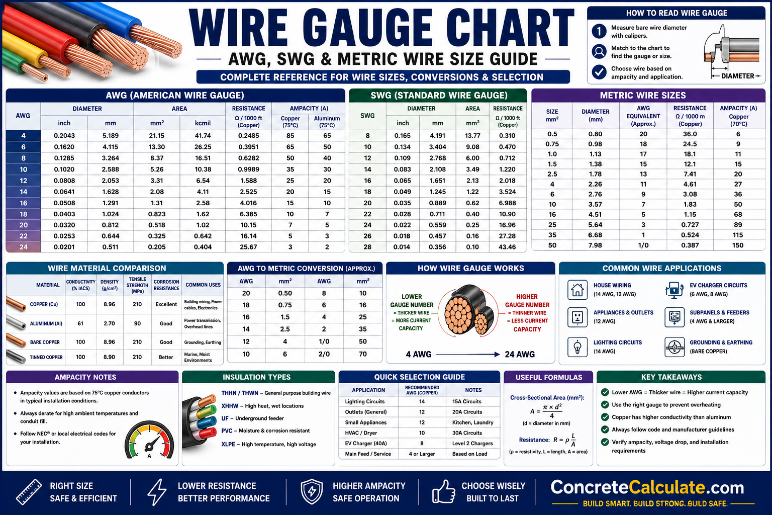
Wire Gauge Chart
AWG, SWG & Metric Sizes
Complete wire gauge reference for electricians and engineers — AWG, SWG, and metric wire sizing, conversions, and selection guidance.
 Reviewed by Muhammad Ramzan Babar, PhD Researcher (Plasma Physics) & Calculator Developer — View Profile
Important: Reference Only, Not a Code Substitute
This page provides wire identification, sizing, and conversion reference information. It intentionally does not reproduce NEC, IEC, or other proprietary ampacity tables, since actual ampacity depends on installation conditions and code edition. Always size electrical conductors per your local electrical code or a licensed electrician’s determination.
⭐ Master Wire Gauge Chart
Complete overview comparing the three major wire sizing systems used across electrical and engineering applications.
How to Read This Chart
Wire gauge describes physical conductor size, not by itself the current it can safely carry — ampacity depends on material, insulation, and installation conditions together. This page focuses on identification, conversion, and general guidance rather than reproducing code-specific ampacity tables.
| System | Sizing Basis | Region | Typical Use |
|---|---|---|---|
| AWG | Gauge number (lower = thicker) | North America | Residential/commercial electrical, electronics |
| SWG | Gauge number (lower = thicker) | UK, Commonwealth (legacy) | Older wiring, some specialty wire products |
| Metric (mm²) | Cross-sectional area directly in mm² | Most of the world | Electrical cable, automotive, industrial |
⭐ American Wire Gauge (AWG) Chart
The primary SEO section — standard AWG sizes with diameter and cross-sectional area.
| AWG Size | Diameter (in) | Diameter (mm) | Area (mm²) | Typical Applications |
|---|---|---|---|---|
| 40 AWG | 0.0031″ | 0.079 mm | 0.0049 mm² | Fine coil windings, micro-electronics |
| 36 AWG | 0.0050″ | 0.127 mm | 0.0127 mm² | Small transformer windings |
| 30 AWG | 0.0100″ | 0.254 mm | 0.0507 mm² | Wire-wrapping, breadboard jumpers |
| 26 AWG | 0.0159″ | 0.404 mm | 0.128 mm² | Signal wiring, small electronics |
| 24 AWG | 0.0201″ | 0.511 mm | 0.205 mm² | Thermostat wire, low-voltage signal |
| 22 AWG | 0.0254″ | 0.643 mm | 0.326 mm² | Low-voltage control wiring |
| 20 AWG | 0.0320″ | 0.812 mm | 0.518 mm² | Speaker wire, small appliance cords |
| 18 AWG | 0.0403″ | 1.024 mm | 0.823 mm² | Lamp cords, low-current extension leads |
| 16 AWG | 0.0508″ | 1.291 mm | 1.31 mm² | Light-duty extension cords, small appliances |
| 14 AWG | 0.0641″ | 1.628 mm | 2.08 mm² | Common lighting circuit conductor |
| 12 AWG | 0.0808″ | 2.053 mm | 3.31 mm² | Common general outlet circuit conductor |
| 10 AWG | 0.1019″ | 2.588 mm | 5.26 mm² | Higher-amperage circuits, water heaters |
| 8 AWG | 0.1285″ | 3.264 mm | 8.37 mm² | Range/dryer circuits, subpanel feeds |
| 6 AWG | 0.1620″ | 4.115 mm | 13.3 mm² | Larger appliance circuits, EV chargers |
| 4 AWG | 0.2043″ | 5.189 mm | 21.1 mm² | Subpanel feeders, larger service runs |
| 2 AWG | 0.2576″ | 6.544 mm | 33.6 mm² | Service entrance, heavy feeders |
| 1 AWG | 0.2893″ | 7.348 mm | 42.4 mm² | Larger service feeders |
| 1/0 AWG | 0.3249″ | 8.252 mm | 53.5 mm² | Main service entrance conductors |
| 2/0 AWG | 0.3648″ | 9.266 mm | 67.4 mm² | Heavier service entrance conductors |
| 3/0 AWG | 0.4096″ | 10.405 mm | 85.0 mm² | Large residential/light commercial service |
| 4/0 AWG | 0.4600″ | 11.684 mm | 107.2 mm² | Heavy service entrance and feeder conductors |
Why “0/0/0” Sizes Exist
Beyond 1 AWG, sizes continue as 1/0, 2/0, 3/0, and 4/0 (also written “0000”) — each is progressively larger, following the same logarithmic pattern as smaller gauge numbers but written with zeros since gauge numbers can’t go below zero using standard digits.
⭐ Standard Wire Gauge (SWG) Chart
The British imperial wire gauge system, historically used throughout the UK and Commonwealth.
| SWG Number | Diameter (mm) | Diameter (inch) |
|---|---|---|
| 7/0 | 12.70 mm | 0.500″ |
| 4/0 | 10.16 mm | 0.400″ |
| 1/0 | 8.23 mm | 0.324″ |
| 10 | 3.25 mm | 0.128″ |
| 16 | 1.63 mm | 0.064″ |
| 20 | 0.914 mm | 0.036″ |
| 24 | 0.559 mm | 0.022″ |
| 30 | 0.315 mm | 0.0124″ |
| 36 | 0.193 mm | 0.0076″ |
SWG is largely a legacy system today, mostly superseded by metric (mm²) sizing in the UK and Commonwealth, but it still appears on some older equipment, specialty wire products, and imported hardware — its diameter progression differs from AWG, so the two are not directly interchangeable size-for-size.
⭐ Metric Wire Size Chart
Standard IEC metric cable sizes with typical applications.
| Wire Size (mm²) | Approx. Diameter | Typical Applications |
|---|---|---|
| 0.5 | 0.80 mm | Low-voltage signal, small appliance cords |
| 0.75 | 0.98 mm | Light fixtures, small appliance cords |
| 1 | 1.13 mm | Lighting circuits (light loads) |
| 1.5 | 1.38 mm | Standard lighting circuits |
| 2.5 | 1.78 mm | Standard socket/outlet circuits |
| 4 | 2.26 mm | Higher-load socket circuits, small appliances |
| 6 | 2.76 mm | Cookers, larger fixed appliances |
| 10 | 3.57 mm | Larger appliance circuits, subpanel feeds |
| 16 | 4.51 mm | Heavier feeders, EV charging circuits |
| 25 | 5.64 mm | Service entrance and heavier feeders |
| 35 | 6.67 mm | Larger service and feeder conductors |
| 50 | 7.98 mm | Heavy feeders, small industrial circuits |
| 70 | 9.44 mm | Industrial feeders |
| 95 | 11.0 mm | Larger industrial feeders |
| 120 | 12.4 mm | Heavy industrial and utility feeders |
| 150 | 13.8 mm | Heavy industrial and utility feeders |
| 185 | 15.3 mm | Large industrial/utility distribution |
| 240 | 17.5 mm | Large-scale distribution feeders |
| 300 | 19.5 mm | Major distribution and utility conductors |
⭐ Wire Gauge by Electrical Application
General guidance by common project type — always confirm against local electrical code.
| Project | Recommended Wire Size (general guidance) |
|---|---|
| Residential Lighting | 14 AWG (typical) |
| General Outlets | 12 AWG (typical) |
| Kitchen Circuits | 12 AWG or larger, per appliance load |
| HVAC Equipment | 10 AWG or larger, per unit nameplate rating |
| Electric Water Heaters | 10 AWG (typical for standard units) |
| Electric Vehicle Chargers | 6–8 AWG for Level 2 charging (per charger rating) |
| Solar Systems | Sized per system voltage/current — often 10–8 AWG for typical residential arrays |
| Industrial Equipment | Varies widely by load — engineered per equipment specification |
| Welding Machines | 6–8 AWG typical for common 220–240V welders |
| Motors | Sized per motor full-load amperage and code requirements |
These Are General Starting Points Only
Final wire sizing depends on the specific equipment’s rated amperage, circuit length, ambient conditions, and the electrical code edition in effect in your jurisdiction — always verify with a licensed electrician before installation.
⭐ AWG vs Metric Wire Size Comparison
One of the most searched comparisons — side-by-side AWG numbers against their metric equivalents.
| AWG Number | Exact Metric Equivalent (mm²) | Nearest Standard Metric (mm²) |
|---|---|---|
| 20 | 0.52 mm² | 0.5 mm² |
| 18 | 0.82 mm² | 1.0 mm² |
| 16 | 1.31 mm² | 1.5 mm² |
| 14 | 2.08 mm² | 2.5 mm² |
| 12 | 3.31 mm² | 4 mm² |
| 10 | 5.26 mm² | 6 mm² |
| 8 | 8.37 mm² | 10 mm² |
| 6 | 13.3 mm² | 16 mm² |
| 4 | 21.1 mm² | 25 mm² |
| 2 | 33.6 mm² | 35 mm² |
| 1/0 | 53.5 mm² | 50–70 mm² |
Notice that the “nearest standard” metric size is always equal to or larger than the exact AWG equivalent — metric cable manufacturers round up to the next standard size rather than producing an exact match, so a metric substitute for an AWG conductor is never undersized.
⭐ Wire Diameter Chart
Comparing actual wire diameters across all three sizing systems at equivalent points.
| Approx. Size Point | AWG Diameter | SWG Diameter | Metric Diameter |
|---|---|---|---|
| ~1.6 mm range | 14 AWG: 1.628 mm | 16 SWG: 1.63 mm | 2.5 mm²: ~1.78 mm |
| ~2.5 mm range | 10 AWG: 2.588 mm | 13 SWG: 2.34 mm | 4 mm²: ~2.26 mm |
| ~4 mm range | 6 AWG: 4.115 mm | 8 SWG: 4.19 mm | 10 mm²: ~3.57 mm |
Because AWG, SWG, and metric progressions each follow their own mathematical spacing, “equivalent” sizes only line up approximately — always confirm the exact diameter or area rather than assuming two systems match at a given nominal number.
Wire Cross-Sectional Area Chart
Understanding area units and their relationship to current-carrying capacity.
| Unit | What It Measures | Common Use |
|---|---|---|
| mm² | Cross-sectional area in square millimeters | Metric cable sizing worldwide |
| Circular Mils | Area based on diameter in mils (1 mil = 0.001 inch) | Basis for AWG size progression |
| kcmil / MCM | Thousand circular mils, used for large conductors | Large AWG-system conductors beyond 4/0 |
Larger cross-sectional area generally means lower resistance and higher current-carrying capacity for a given material and length, which is why cross-sectional area — not gauge number — is the true physical driver behind ampacity.
⭐ Wire Gauge by Ampacity
General guidance only — actual ampacity always depends on multiple installation-specific factors.
| Wire Size | General Ampacity Character |
|---|---|
| 14 AWG | Lower current range, common for lighting circuits |
| 12 AWG | Moderate current range, common for general outlets |
| 10 AWG | Higher current range, common for larger fixed appliances |
| 8 AWG | Higher current range, larger appliance and feeder circuits |
| 6 AWG and larger | High current range, feeders and heavy equipment circuits |
Why Exact Ampacity Isn’t Shown Here
Real ampacity ratings depend on conductor material (copper vs aluminum), insulation type and its temperature rating, installation method (conduit, free air, buried, bundled), ambient temperature, and the number of current-carrying conductors grouped together — these factors combine differently in every code edition and jurisdiction. Always reference the current NEC/IEC ampacity tables or consult a licensed electrician for actual circuit sizing.
⭐ Copper vs Aluminum Wire Comparison
The two dominant conductor materials, compared on the factors that actually matter for selection.
| Factor | Copper | Aluminum |
|---|---|---|
| Conductivity | Higher; smaller conductor for same ampacity | Lower; requires larger conductor for same ampacity |
| Weight | Heavier per unit length | About 1/3 the weight of copper for same length |
| Cost | Higher material cost | Lower material cost |
| Corrosion Resistance | Good, minimal oxidation issues | Forms oxide layer, needs proper connectors/anti-oxidant paste |
| Common Applications | Most residential and commercial branch circuits | Service entrance conductors, large feeders, overhead lines |
Solid vs Stranded Wire Chart
Construction type affects flexibility, installation, and best-fit applications.
| Factor | Solid Wire | Stranded Wire |
|---|---|---|
| Flexibility | Lower, more rigid | Higher, bends easily |
| Conductivity | Slightly better for equivalent gauge | Slightly more surface area, comparable performance |
| Installation | Easier to terminate in some connectors, holds shape | Preferred where movement or vibration occurs |
| Applications | Fixed residential branch circuit wiring | Flexible cords, automotive, panels requiring flexibility |
Wire Gauge by Voltage System
General notes by common voltage system — actual sizing depends on current, not voltage alone.
| System | General Note |
|---|---|
| 12V DC | Low-voltage systems often need larger gauge for the same power due to higher current at low voltage |
| 24V DC | Common in control circuits and some solar systems; sizing follows current and run length |
| 120V AC | Standard US residential branch circuit voltage |
| 230V AC | Standard residential voltage in much of the world outside North America |
| 400V Three-Phase | Common industrial/commercial three-phase distribution voltage |
Conductor size should ultimately be determined by current draw, acceptable voltage drop, and applicable code — voltage system alone does not determine wire size.
Wire Gauge by Material
Beyond copper and aluminum, several hybrid and coated conductor types exist for specific needs.
| Material | Advantages | Limitations |
|---|---|---|
| Copper | High conductivity, reliable, widely accepted | Higher cost, heavier than aluminum |
| Aluminum | Lightweight, lower cost, common for large feeders | Lower conductivity, requires larger size and proper connectors |
| Tinned Copper | Improved corrosion resistance, easier soldering | Slightly higher cost than bare copper |
| Copper-Clad Aluminum (CCA) | Lighter and cheaper than solid copper | Lower conductivity than copper; not code-accepted for many circuits |
Wire Gauge by Insulation Type
Common insulation types and where each is typically specified.
| Insulation Type | Typical Use |
|---|---|
| THHN | Dry indoor conduit wiring |
| THWN | Wet or dry locations, conduit wiring |
| XHHW | Wet or dry locations, higher temperature rating |
| NM-B | Standard indoor residential branch circuit cable |
| UF-B | Direct burial and wet location cable |
| XLPE | Power distribution cable, cross-linked polyethylene insulation |
Wire Gauge by Installation Type
Installation method affects heat dissipation and therefore the appropriate insulation and ampacity margin.
| Installation Type | General Note |
|---|---|
| Conduit | THHN/THWN typical; derating applies with multiple bundled conductors |
| Underground | UF-B or conduit-protected wet-rated cable required |
| Outdoor | Weather and UV-resistant rated cable required |
| Indoor | NM-B common for residential branch circuits |
| Tray Cable | Cable rated specifically for open tray support systems |
| Flexible Cable | Stranded conductors, cord-rated insulation for movement |
| Automotive Wiring | Stranded, often thinner-wall insulation rated for vibration and heat |
⭐ Wire Resistance Chart
Approximate copper conductor resistance by size, illustrating how resistance changes with gauge.
| Wire Size | Resistance per 1000 ft (approx.) | Resistance per 100 m (approx.) |
|---|---|---|
| 14 AWG | 2.53 Ω | 0.83 Ω |
| 12 AWG | 1.59 Ω | 0.52 Ω |
| 10 AWG | 0.999 Ω | 0.33 Ω |
| 8 AWG | 0.628 Ω | 0.21 Ω |
| 6 AWG | 0.395 Ω | 0.13 Ω |
| 4 AWG | 0.249 Ω | 0.08 Ω |
Resistance roughly doubles for every 3 AWG sizes going up (smaller wire) — this is why voltage drop becomes a much bigger concern on thinner conductors, especially over long runs.
Wire Gauge vs Current Capacity
Clarifying the inverse relationship between AWG number and wire size.
Smaller Number = Bigger Wire
In the AWG system, a smaller gauge number means a larger physical wire — 10 AWG is thicker than 14 AWG, and 4/0 AWG is thicker than 1 AWG. A larger gauge number means a smaller, thinner wire with less current-carrying capability. Generally, larger conductor size increases safe current-carrying capability because more cross-sectional area lowers resistance and improves heat dissipation, but the exact ampacity always depends on the additional factors covered in the Ampacity section above.
Wire Gauge vs Voltage Drop
One of the highest-value educational sections — understanding why length and current both matter.
Why Voltage Drop Matters
Every conductor has some resistance, and that resistance causes a small voltage loss along the wire’s length as current flows through it. This loss grows proportionally with both the current drawn and the total wire length (there and back), and shrinks as wire cross-sectional area increases. On short runs with light loads, voltage drop is usually negligible — but on long circuit runs (like a detached garage or a well pump far from the panel) or with high-current loads, drop can become significant enough to dim lights, reduce motor performance, or trip protective devices. Minimizing voltage drop generally means upsizing the conductor beyond the minimum ampacity requirement for long or heavily loaded runs.
⭐ Wire Gauge Conversion Chart
Excellent SEO potential — cross-referencing AWG, SWG, and metric mm² at common size points.
| AWG | Nearest SWG | Nearest Metric (mm²) |
|---|---|---|
| 18 | 19 SWG | 1.0 mm² |
| 16 | 17 SWG | 1.5 mm² |
| 14 | 15 SWG | 2.5 mm² |
| 12 | 13 SWG | 4 mm² |
| 10 | 11 SWG | 6 mm² |
| 8 | 9 SWG | 10 mm² |
| 6 | 7 SWG | 16 mm² |
| 4 | 5 SWG | 25 mm² |
| 2 | 3 SWG | 35 mm² |
These are approximate nearest-size matches, not exact conversions — always verify the actual diameter or area when substituting between systems for a critical application.
⭐ Wire Selection Guide
Quick decision reference matching common projects to typical wire size with reasoning — always verify with local code.
| Project | Recommended Wire (general guidance) | Why |
|---|---|---|
| Home Lighting | 14 AWG | Matches typical lighting circuit current draw |
| Kitchen Outlet | 12 AWG | Handles higher small-appliance current common in kitchens |
| Air Conditioner | 10 AWG or larger | Matches typical AC unit nameplate amperage |
| Electric Water Heater | 10 AWG | Standard for common residential electric water heater loads |
| Solar Panel | 10–8 AWG (system-dependent) | Sized to array current and inverter/combiner requirements |
| EV Charger | 6–8 AWG (charger-dependent) | Matches Level 2 charger continuous current rating |
| Welding Machine | 6–8 AWG | Handles higher startup and operating current of common welders |
| Workshop | 12–10 AWG for general circuits | Balances flexibility for varied tool loads |
| Motor Circuit | Sized to motor full-load amps | Motor starting current requires engineered sizing margin |
⭐ Visual Wire Gauge Guide
Original engineering diagrams explaining AWG scale, wire construction, and measurement technique.
Common Wire Selection Mistakes
Avoiding these errors prevents overheating, code violations, and connection failures.
Assuming Larger AWG Numbers Mean Larger Wires
The opposite is true — a higher AWG number means a smaller, thinner conductor, not a larger one.
Ignoring Voltage Drop on Long Runs
Sizing only for minimum ampacity on a long circuit can result in excessive voltage drop, dimming lights or reducing motor performance.
Mixing Copper and Aluminum Conductors Improperly
Direct copper-to-aluminum connections without proper anti-oxidant compound and rated connectors can cause galvanic corrosion and connection failure.
Choosing Wire by Voltage Instead of Current
Wire size is driven primarily by current (amperage) and length, not the system voltage alone.
Using Indoor Cable Outdoors
Standard indoor-rated cable lacks the UV and moisture resistance needed for exterior or underground use.
Overlooking Insulation Temperature Ratings
Using a lower temperature-rated insulation than the installation demands can shorten wire life and create a fire hazard.
Confusing AWG, SWG, and Metric Sizing
Assuming a numeric match between systems (like “12 AWG = 12 SWG”) ignores that each system follows its own diameter progression.
Using CCA Wire Where Pure Copper Is Required
Copper-Clad Aluminum has lower conductivity and is not accepted by many electrical codes for standard branch circuit wiring.
Electrician Worked Examples
Real-world wire sizing scenarios for common project types — always verify final sizing with local code.
Kitchen Receptacle Circuit
EV Charger Installation
Frequently Asked Questions
📄 Download Wire Gauge Chart PDF
Get a printable electrician and engineer reference including AWG tables, SWG tables, metric wire sizes, wire conversion chart, resistance guide, material comparison, wire selection guide, SVG measurement diagrams, and field-ready quick reference sheet.