Rebar Coupler Size Chart: #4-#18 Sizes & Dimensions
U.S. rebar sizes paired with manufacturer-documented coupler dimensions, plus Type 1 and Type 2 splice classes, bar-grade compatibility, cover, spacing, and inspection guidance.
 Reviewed by Muhammad Ramzan Babar, PhD Researcher (Plasma Physics) & Calculator Developer. View Profile
⭐ Rebar Coupler Size Chart: Quick Reference
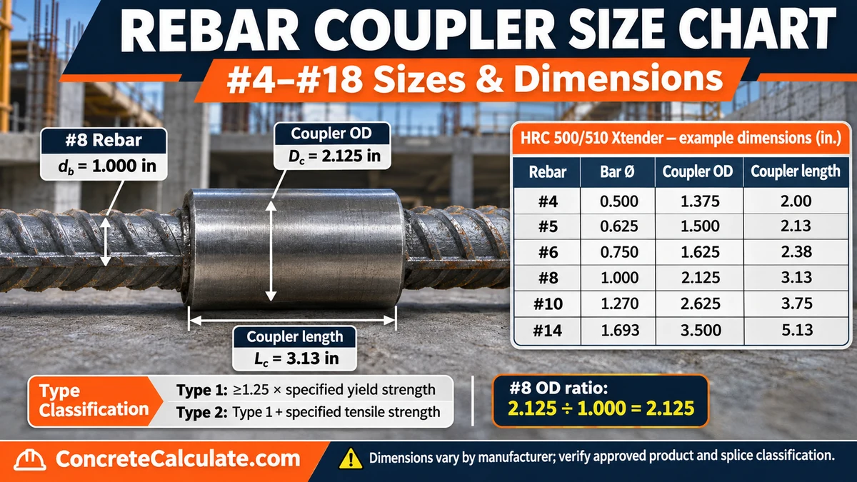
A rebar coupler size chart pairs each U.S. bar size with real coupler dimensions, but coupler size is product-specific: in the HRC 500/510 Xtender system a #8 bar (1.000 in.) uses a 2.125 in. outside diameter, 3.13 in. long coupler. Always verify the approved product, bar grade, and Type 1 or Type 2 classification.
U.S. Rebar Sizes and Coupler Dimensions
| Rebar size | Metric bar designation | Nominal bar diameter (in.) | Bar diameter (mm) | HRC 500/510 coupler OD (in.) | Typical coupler length (in.) |
|---|---|---|---|---|---|
| #3 | #10 | 0.375 | 9.53 | Not listed | Not listed |
| #4 | #13 | 0.500 | 12.70 | 1.375 | 2.00 |
| #5 | #16 | 0.625 | 15.88 | 1.500 | 2.13 |
| #6 | #19 | 0.750 | 19.05 | 1.625 | 2.38 |
| #7 | #22 | 0.875 | 22.23 | 1.875 | 2.88 |
| #8 | #25 | 1.000 | 25.40 | 2.125 | 3.13 |
| #9 | #29 | 1.128 | 28.65 | 2.375 | 3.50 |
| #10 | #32 | 1.270 | 32.26 | 2.625 | 3.75 |
| #11 | #36 | 1.410 | 35.81 | 2.875 | 4.25 |
| #14 | #43 | 1.693 | 43.00 | 3.500 | 5.13 |
| #18 | #57 | 2.257 | 57.33 | Not listed | Not listed |
Sources: coupler OD and typical length from Table 1 of ICC-ES ESR-2764 (reissued March 2026, copy hosted by Headed Reinforcement Corp.); nominal bar diameters per ASTM A615 as listed in the Caltrans BCM 52-1, Attachment 3 and on the ConcreteCalculate Rebar Diameter Chart. Metric diameters are calculated from the inch values and rounded to two decimals. Not listed means the size is not in this product series, not that no coupler exists.
✓ Verified against ICC-ES ESR-2764 Tables 1 and 2 (reissued March 2026) and the manufacturer’s published copy, November 2026- The dimensions apply only to the named system, the HRC 500/510 Xtender coupler. They are not universal coupler dimensions or an ACI-prescribed schedule.
- OD is the external diameter of the coupler body. Typical length is the manufacturer-reported assembly dimension, not a minimum splice length.
- Approval also depends on the bar grade and bar-end preparation. Use current product data and approved construction drawings for the final selection.
How to Read the Chart
Find the bar size, then read the product series OD and length. #3 and #18 are not in this series; the series covers #4 through #11 and #14.
Why Coupler Dimensions Vary by Manufacturer
Couplers are proprietary mechanical splice systems. Threaded, upset-threaded, swaged, bolt-locking, and other designs have different geometry, so no single OD or length chart covers every manufacturer.
#8 bar and its HRC 500/510 coupler
The splice needs more lateral space than the bare bar, so cover, adjacent bars, and access must be checked against actual assembly dimensions.
What Is a Rebar Coupler?
A rebar coupler is a mechanical splice that joins two reinforcing bars end to end so force transfers through the device instead of through overlapping bar lengths.
Mechanical Splice Definition
Mechanical splices connect bars in tension, compression, or both. A structural coupler is different from a sleeve used only to position bars.
How a Coupler Transfers Force
Force passes through the threads, upset heads, grips, or locking elements of the system, so each design has its own installation and inspection rules.
Couplers vs. Overlapping Reinforcement
A lap splice relies on bond with surrounding concrete. A mechanical splice does not, but it adds product qualification and clearance requirements. See Section 21.
⭐ How Rebar Sizes Relate to Coupler Sizes
Rebar size sets nominal bar diameter, such as 1.000 in. for #8, but coupler OD and length come from the selected product, about 2.1 times the bar diameter in the HRC 500/510 series.
| Rebar size | Nominal bar diameter db (in.) | Coupler OD Dc (in.) | Ratio Dc ÷ db |
|---|---|---|---|
| #4 | 0.500 | 1.375 | 2.75 |
| #5 | 0.625 | 1.500 | 2.40 |
| #6 | 0.750 | 1.625 | 2.17 |
| #7 | 0.875 | 1.875 | 2.14 |
| #8 | 1.000 | 2.125 | 2.12 |
| #9 | 1.128 | 2.375 | 2.11 |
| #10 | 1.270 | 2.625 | 2.07 |
| #11 | 1.410 | 2.875 | 2.04 |
| #14 | 1.693 | 3.500 | 2.07 |
Ratio = Dc ÷ db for this product series only. Calculated from the table above.
✓ Calculated from verified values, arithmetic checked, November 2026Coupler-to-bar diameter ratio, #6
Illustrates the extra space needed at the splice.
U.S. Rebar Numbers and ASTM Metric Designations
For #3 through #8 the number is the diameter in eighths of an inch; larger bars follow the ASTM table (for example #10 = 1.270 in.). See the Rebar Number Chart, Rebar Diameter Chart, and Rebar Size Chart. Soft-metric labels such as #25 are ASTM designations of the same U.S. bar family, not separate 25 mm bars.
⭐ Rebar Coupler Dimensions: OD, Length and Thread Engagement
Coupler OD, overall length, and thread engagement are separate product dimensions: an HRC 300 coupler for a #8 bar has 1.50 in. OD, 3.00 in. length, and 1.13 in. minimum engagement.
| Dimension | Symbol | Meaning | Example (HRC 300, #8) |
|---|---|---|---|
| Nominal bar diameter | db | ASTM nominal bar size | 1.000 in. |
| Coupler outside diameter | Dc (D in ESR-2764 Table 2) | External diameter of the coupler body | 1.50 in. |
| Overall coupler length | Lc (L in ESR-2764 Table 2) | Length of the coupler body | 3.00 in. |
| Minimum thread engagement | T | Manufacturer-defined engagement of the threaded bar into the coupler | 1.13 in. |
Example values from Table 2 of ICC-ES ESR-2764 (reissued March 2026, copy hosted by Headed Reinforcement Corp.). T is defined by the manufacturer, not by ACI, and applies to HRC 300 only.
✓ Verified against ICC-ES ESR-2764 Tables 1 and 2 (reissued March 2026) and the manufacturer’s published copy, November 2026Internal Thread Size and Bar-End Preparation
HRC 300 bars are threaded with a UNC thread matching the bar size, while HRC 500/510 bars have headed (upset) ends, so the two systems cannot share one dimension schedule.
Rebar Coupler Types and Their Applications
Mechanical rebar couplers include threaded, upset-threaded, swaged, bolt-locking, and grouted systems, and they do not all share the same code classification.
| Type | Connection mechanism | Bar preparation | Examples of listed systems |
|---|---|---|---|
| Parallel or standard threaded | Threads on bar ends and coupler | Threaded ends | Threaded bar splicing systems |
| Tapered threaded | Tapered threads | Tapered-threaded ends | Taper-lock couplers |
| Upset threaded | Forged upset heads with threaded coupler | Upset (headed) ends | HRC 500/510 Xtender |
| Swaged or friction-welded | Sleeve crimped or friction-welded to bar | Specialized equipment | Frictional weld couplers |
| Bolt-locking | Shear-head bolts bite into the bars | Plain bar ends | Shear bolt splicing systems |
| Grouted or other | Grout or other filler in a sleeve | Per system | Specialty sleeves |
Systems named from the ACI-hosted presentation on ACI 318-19 mechanical splices and from state DOT approved-coupler lists (for example the Caltrans steel reinforcing couplers list). Classification and approval are product-specific.
Choose the type by constructability: whether bars can rotate, how congested the splice zone is, and what bar-end equipment is available.
Standard Threaded Rebar Coupler Size Chart
A #8 bar does not automatically fit a generic 1 in. coupler thread, because each manufacturer defines its own thread form and bar-end preparation, as the HRC 300 and HRC 500/510 systems show.
| Item | HRC 300 Form Protector | HRC 500/510 Xtender |
|---|---|---|
| Bar-end preparation | Bar threaded by HRC (UNC thread) | Bar heated and upset to form a head |
| Thread or connection | 1/2″-13 UNC to 1″-8 UNC for #4 to #8 | Male and female threaded components |
| Bar sizes | #4 through #8 | #4 through #11 and #14 |
| Bar grade | ASTM A615 or A706 Grade 60 | Grade 60, 75, or 80 depending on size |
Source: ICC-ES ESR-2764 (reissued March 2026, copy hosted by Headed Reinforcement Corp.), Sections 3.1, 3.2, and Tables 1 and 2.
✓ Verified against ICC-ES ESR-2764 Tables 1 and 2 (reissued March 2026) and the manufacturer’s published copy, November 2026Do not mix thread forms
Never substitute threads or couplers between manufacturers. Threaded bar ends must be prepared as the approved system requires.
Positional Rebar Couplers for Fixed Bars
A positional coupler such as the HRC 500/510 lets pre-bent and pre-tied bars be joined without rotating either bar, by screwing male and female coupler components together.
When Reinforcing Bars Cannot Rotate
Preassembled cages, bent bars, and some columns cannot spin. ESR-2764 describes the HRC 500/510 as a positional coupler for exactly that case.
Positional Coupler Components
The system has an HRC 500 male threaded component, an HRC 510 female component, and two bars with headed upset ends (ICC-ES ESR-2764 (reissued March 2026, copy hosted by Headed Reinforcement Corp.)).
Assembly and Installation Clearance
Components are hand-tightened snug without rotating the bars. Access to the splice and adjacent reinforcement must be checked.
⭐ Rebar Coupler Size Chart for #4 Through #8 Bars
The HRC 300 Form Protector coupler for #4 through #8 bars ranges from 1.75 in. long and 0.88 in. in diameter at #4 to 3.00 in. long and 1.50 in. in diameter at #8.
| Rebar size | Bar diameter (in.) | Thread designation | Minimum engagement T (in.) | Coupler length L (in.) | Coupler diameter D (in.) |
|---|---|---|---|---|---|
| #4 | 0.500 | 1/2″-13 UNC | 0.75 | 1.75 | 0.88 |
| #5 | 0.625 | 5/8″-11 UNC | 0.75 | 2.00 | 1.00 |
| #6 | 0.750 | 3/4″-10 UNC | 1.00 | 2.13 | 1.13 |
| #7 | 0.875 | 7/8″-9 UNC | 1.00 | 2.50 | 1.25 |
| #8 | 1.000 | 1″-8 UNC | 1.13 | 3.00 | 1.50 |
Source: ICC-ES ESR-2764 (reissued March 2026, copy hosted by Headed Reinforcement Corp.), Table 2. HRC 300 couplers develop the minimum tensile strength of ASTM A706 or A615 Grade 60 bars. T is the manufacturer-defined engagement, not an ACI requirement, and generic threaded bars cannot be assembled with this coupler.
✓ Verified against ICC-ES ESR-2764 Tables 1 and 2 (reissued March 2026) and the manufacturer’s published copy, November 2026These thread sizes belong to this system and are not a standard for all #4 to #8 couplers.
Large Rebar Couplers for #9, #10, #11, #14 and #18
The HRC 500/510 series covers #9 through #11 and #14 with ODs from 2.375 to 3.500 in. and lengths from 3.50 to 5.13 in., while #18 needs a separately verified product.
| Rebar size | Bar diameter (in.) | Coupler OD (in.) | Typical length (in.) | Approved reinforcement (ESR-2764) |
|---|---|---|---|---|
| #9 | 1.128 | 2.375 | 3.50 | A615 Gr 60; A706 Gr 60; A615 Gr 80; A706 Gr 80 |
| #10 | 1.270 | 2.625 | 3.75 | A615 Gr 60; A706 Gr 60; A615 Gr 80; A706 Gr 80 |
| #11 | 1.410 | 2.875 | 4.25 | A615 Gr 60; A706 Gr 60; A615 Gr 75; A615 Gr 80; A706 Gr 80 |
| #14 | 1.693 | 3.500 | 5.13 | A615 Gr 60; A706 Gr 60; A615 Gr 75; A615 Gr 80; A706 Gr 80 |
Source: ICC-ES ESR-2764 (reissued March 2026, copy hosted by Headed Reinforcement Corp.), Table 1 and Section 3.2.1.1. #18 is not in this report. Other manufacturers list #18 couplers (for example on state DOT approved lists), so verify availability and approval for the specific product.
✓ Verified against ICC-ES ESR-2764 Tables 1 and 2 (reissued March 2026) and the manufacturer’s published copy, November 2026Coupler Size and Installation Space
A #14 coupler is 3.500 in. in diameter, about 2.07 times the bar. Space for tools and consolidation grows with size.
Why Not Scale a Smaller Model
Couplers are not selected by scaling a smaller model. Each size has its own listed dimensions and approvals.
⭐ Type 1 vs. Type 2 Rebar Couplers
A Type 1 mechanical splice must develop at least 1.25 times the bar yield strength, while a Type 2 splice must also develop the bar’s specified tensile strength, which is a performance difference, not a size difference.
| Property | Type 1 | Type 2 |
|---|---|---|
| ACI 318-19 basis | Section 25.5.7 | Sections 25.5.7 and 18.2.7 |
| Strength requirement | At least 1.25 fy in tension or compression, as required | Meets Type 1 and develops the specified tensile strength of the spliced bar |
| Seismic application | Location restrictions apply; not for yielding regions | Permitted where inelastic cyclic response is expected, subject to code limits |
| Bar-grade compatibility | Product-specific | Product-specific |
| Installation | Approved product procedure | Approved product procedure |
| Verification | Product testing and applicable approval | Product testing and applicable approval |
Summarized from the ACI-hosted presentation on ACI 318-19 mechanical splices of ACI 318-19 Sections 18.2.7 and 25.5.7; the presentation states Type 2 splices on Grade 60 reinforcement are permitted at any location. Confirm the adopted code edition. Type 2 is not an unrestricted permission for all high-strength reinforcement.
✓ Checked against the ACI-hosted presentation of ACI 318-19, November 2026| Rebar size | Nominal area Ab (in²) | Threshold force (kips) |
|---|---|---|
| #4 | 0.20 | 15.00 |
| #5 | 0.31 | 23.25 |
| #6 | 0.44 | 33.00 |
| #7 | 0.60 | 45.00 |
| #8 | 0.79 | 59.25 |
| #9 | 1.00 | 75.00 |
| #10 | 1.27 | 95.25 |
| #11 | 1.56 | 117.00 |
| #14 | 2.25 | 168.75 |
Areas per ASTM A615 as shown on the ConcreteCalculate Rebar Area Chart and in ESR-2764 (#4 to #8). A calculated threshold, not a certified coupler capacity or design load.
✓ Calculated from verified values, arithmetic checked, November 2026Type 1 strength threshold, #8 Grade 60
This is the calculated Type 1 threshold for the assumed bar, not a manufacturer-certified capacity.
How to Verify the Approved Classification
Check the evaluation report and the coupler marking. ESR-2764 says the HRC couplers are used as Type 1 or Type 2 splices and are stamped “T2” for Type 2 use. See the Rebar Area Chart for bar areas.
ACI 318 Requirements for Mechanical Rebar Splices
ACI 318-19 requires mechanical splices to meet Type 1 or Type 2 strength levels in Sections 25.5.7 and 18.2.7, and the 2024 and 2021 IBC reference ACI 318-19, not the newer ACI CODE-318-25.
| IBC edition | ACI 318 edition referenced | Mechanical splice sections |
|---|---|---|
| 2024 and 2021 IBC | ACI 318-19 | 25.5.7.1 and 18.2.7.1 |
| 2018 and 2015 IBC | ACI 318-14 | Corresponding sections |
| 2012 and 2009 IBC | ACI 318-11 and 318-08 | 12.14.3.2 and 21.1.6.1 |
Source: Section 2.0 of ICC-ES ESR-2764 (reissued March 2026, copy hosted by Headed Reinforcement Corp.). ACI CODE-318-25 was published in 2025 (ACI CODE-318-25), but the edition referenced by the adopted building code and the project documents governs.
✓ Edition mapping read directly from ESR-2764, November 2026Mechanical Splice Strength
See the Type 1 and Type 2 table.
Detailing and Construction Documents
Splice locations must be shown on plans approved by the code official, and product installation instructions are separate from code requirements. Do not assume a newer ACI edition governs without checking the adopted code.
ICC-ES Evaluation Reports and AC133 Qualification
ICC-ES AC133(24), 2nd edition (April 2025), is the acceptance criteria behind ESR-2764, which documents the approved sizes, grades, dimensions, installation, and marking of the HRC couplers.
| Report item | What it says |
|---|---|
| Evaluation subject | HRC 500/510 Xtender and HRC 300 Series Form Protector mechanical couplers |
| Status | Reissued March 2026; subject to renewal March 2027 |
| Codes evaluated | 2024, 2021, 2018, 2015, 2012, and 2009 IBC |
| Acceptance criteria | ICC-ES AC133(24), 2nd edition, published April 2025 |
| Sizes | HRC 500/510: #4 to #11 and #14; HRC 300: #4 to #8 |
| Identification | Couplers stamped with product designation, bar size, lot number, and “T2”; packaging shows ESR-2764 |
| Special inspection | Verify bar grade and size, coupler identification, heading of bars, field preparation, coupler position, splice placement, and assembly |
Source: ICC-ES ESR-2764 (reissued March 2026, copy hosted by Headed Reinforcement Corp.). The official report is also in the ICC-ES report directory; recheck the current report before relying on any value.
✓ Read directly from ESR-2764, November 2026An evaluation report establishes that a product complies with the cited code as a suitable alternative, within the report’s conditions of use. It does not extend to other manufacturers’ couplers.
⭐ Rebar Coupler Compatibility With ASTM Steel Grades
A coupler approved for ASTM A615 Grade 60 is not automatically approved for Grade 80, so the HRC 500/510 report lists a different grade set for each bar size.
| Rebar sizes | Approved reinforcement listed in ESR-2764 |
|---|---|
| #4 through #11 and #14 | ASTM A706 Grade 60; ASTM A615 Grade 60 |
| #8, #11 and #14 | ASTM A615 Grade 75 |
| #8 through #11 and #14 | ASTM A706 Grade 80; ASTM A615 Grade 80 |
Source: ICC-ES ESR-2764 (reissued March 2026, copy hosted by Headed Reinforcement Corp.), Section 3.2.1.1. Each row is a permitted combination within this evaluated system. Grade 100 is not listed in this report. HRC 300 is limited to ASTM A706 and A615 Grade 60. See the Rebar Grade Chart.
✓ Read directly from ESR-2764 Section 3.2.1.1, November 2026ASTM A615, A706, and Higher-Strength Reinforcement
Check each bar size and grade combination in the current report. Do not extend an approval to Grade 100 or to a different product.
Rebar Couplers in Seismic Design
In seismic design the splice classification and location matter: ACI 318-19 restricts Type 1 splices in yielding regions, and ESR-2764 permits its Type 2 couplers in any member location unless ACI says otherwise.
Special Moment Frames and Structural Walls
For special moment frames and special structural walls, ESR-2764 requires mill certificates showing the bars meet ACI 318-19 Section 20.2.2.5 under the 2024 and 2021 IBC.
Potential Yielding Regions and Type 2 Location Restrictions
ACI limits Type 1 splices away from yielding regions; Type 2 on Grade 60 is permitted at any location, and other grades must be checked against the adopted code (ACI-hosted presentation on ACI 318-19 mechanical splices). A yes-or-no seismic rating cannot be assigned from the coupler size.
⭐ Rebar Coupler Concrete Cover Requirements
Minimum concrete cover is measured from the outer surface of the coupler, so a #8 HRC 500/510 coupler with 2.00 in. of cover to its surface puts the centerline 3.0625 in. from the face.
| Example | Given dimensions | Calculated result | Meaning |
|---|---|---|---|
| #8 adjacent couplers | 4.00 in. centers, 2.125 in. OD each | 1.875 in. clear gap | Physical gap between equal couplers |
| #6 adjacent couplers | 3.00 in. centers, 1.625 in. OD each | 1.375 in. clear gap | Physical gap only |
| #8 cover offset | 2.125 in. OD, assumed 2.00 in. cover | 3.0625 in. centerline offset | Geometric positioning example |
| #11 cover offset | 2.875 in. OD, assumed 2.00 in. cover | 3.4375 in. centerline offset | Geometric positioning example |
Calculated from OD values in ESR-2764 Table 1. The 2.00 in. cover is illustrative, not a code value. ESR-2764 requires spacing and cover (ACI 318 Sections 7.7.2.3, 8.7.2.2, 11.7.2, 20.6.1, 25.2, 25.5, and 25.6) to be measured from the outside of the coupler. Compliance must be checked on the structural drawings.
✓ Calculated from verified values, arithmetic checked, November 2026Cover offset for a #8 coupler
The 2.00 in. cover is an assumption. Use the project specification and governing code.
Cover vs. Bar Centerline
Larger couplers push the bar centerline deeper into the member. Do not use one universal cover; see the Concrete Cover Chart.
Rebar Coupler Clear Spacing and Congestion
Two #8 HRC 500/510 couplers at 4.00 in. centers leave only a 1.875 in. clear gap, which must still fit concrete placement, consolidation, and adjacent reinforcement.
Clear gap between two #8 couplers
For unequal couplers use s_clear = s_center – (D1 + D2) ÷ 2. The physical gap does not prove ACI compliance.
Coupler-to-Stirrup Clearance and Placement Access
Check stirrup positions, aggregate passage, and tool access. Staggering couplers often helps (Section 17).
Rebar Coupler Splice Locations and Staggering
Splice locations must be detailed on the plans approved by the code official, and no universal stagger offset applies to every mechanical splice.
Locations Shown on Structural Drawings
ESR-2764 requires splice locations to be shown on approved plans and to comply with IBC requirements.
Staggering and Special-Member Restrictions
Staggering and seismic location limits come from the adopted ACI provisions and the structural drawings, not from a fixed offset. Coordinate with the reinforcement layout.
How to Install Threaded Rebar Couplers
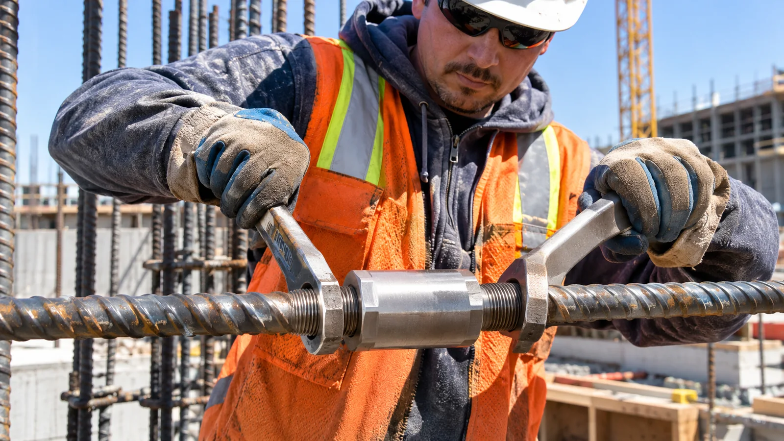
Install a coupler by verifying the bar and product, preparing bar ends as the approved system requires, assembling to the report’s tightening and visual criteria, and completing the required inspection.
- Verify bar size and product against the drawings and the evaluation report.
- Prepare the bar ends: for HRC 500/510 this means a headed (upset) end; for HRC 300 a thread cut by HRC.
- Assemble the coupler with right-handed threads, hand-tight to a snug fit; lubricate and use wrenches if necessary.
- Verify engagement: full threads must not be visible, and the male collar and female sleeve must not bottom out (HRC 500/510).
- Perform the required inspection and keep the records.
Jobsite upsetting for HRC 500/510 needs straight bar of about six bar diameters (not less than 6 in.) and is done by an approved fabricator (ICC-ES ESR-2764 (reissued March 2026, copy hosted by Headed Reinforcement Corp.)). Follow the manufacturer’s instructions for any other system.
Rebar Coupler Thread Engagement and Torque
ESR-2764 requires the HRC 300 bar to engage at least T (0.75 in. for #4 and #5, 1.00 in. for #6 and #7, 1.13 in. for #8) and calls for snug hand-tightening, not a stated torque.
| System | Tightening | Visual or dimensional check |
|---|---|---|
| HRC 500/510 Xtender | Hand-tighten to a snug fit; lubricate threads and use wrenches if necessary | Full threads not visible; male collar and female sleeve must not touch or bottom out |
| HRC 300 Form Protector | Hand-tighten to a snug fit; lubricate threads and use wrench if necessary | Full bar threads not visible; bar engages at least T (0.75 to 1.13 in. for #4 to #8) |
Source: ICC-ES ESR-2764 (reissued March 2026, copy hosted by Headed Reinforcement Corp.), Sections 4.2.1 to 4.2.3. The report specifies snug hand-tightening, not a torque value, for these two systems. Do not assume every threaded system is torque-controlled or transfer these values to other manufacturers.
✓ Read directly from ESR-2764, November 2026Common Installation Errors
Typical errors are incomplete engagement, thread debris or rust, wrong product pairing, and treating one system’s values as universal.
Rebar Couplers for Columns, Beams and Walls
Couplers are used in columns, beams, walls, and precast work, and the choice is driven by constructability, splice classification, and location, not by the member name.
| Member | Constructability consideration |
|---|---|
| Column vertical bars | Position of splices, bar rotation, and access above the footing or floor |
| Beams | Congestion at supports and the choice of splice location |
| Wall boundary reinforcement | Seismic splice classification and location |
| Precast and staged construction | Form-mounted couplers allow continuity without damaging formwork (HRC 300) |
General considerations; the structural drawings and engineer govern. No coupler type is universally appropriate for each member.
Rebar Couplers vs. Lap Splices
A mechanical coupler transfers force through a device while a lap splice relies on bond, so couplers cut overlap length but add qualification, clearance, and inspection requirements.
| Topic | Mechanical coupler | Lap splice |
|---|---|---|
| Force transfer | Through the coupler device | Through bond with concrete |
| Congestion | More local width, fewer overlapping bars | Overlapping bars can congest the zone |
| Material | No overlap bar length | Extra bar length for the lap |
| Qualification and inspection | Product evaluation, markings, installation inspection | Detailing and placement inspection |
| When appropriate | Large bars, congested zones, positions where laps are impractical | Conventional lengths and uncongested zones |
A coupler does not always replace a lap of a fixed number of bar diameters. For lap lengths see the Rebar Lap Splice Chart.
How to Calculate Rebar Coupler Quantities
Coupler quantity equals the number of mechanical splice joints per bar size, so splice locations of 48, 32, 20, and 8 give 108 couplers when each joint uses one assembly.
| Bar size | Splice locations | Couplers per splice | Total couplers |
|---|---|---|---|
| #5 | 48 | 1 | 48 |
| #6 | 32 | 1 | 32 |
| #8 | 20 | 1 | 20 |
| #10 | 8 | 1 | 8 |
| Total | 108 |
Illustrative takeoff, not a real project quantity. If a connection uses several separately ordered components, list each component in the bill of materials rather than assuming one packaged item contains the whole connection.
✓ Calculated from verified values, arithmetic checked, November 2026Total coupler quantity
Count splice joints, not bars: each joint joins two bar ends.
Prepare a Coupler Takeoff Schedule
List product, bar size, grade, and any bar-end preparation separately for each product system.
Rebar Coupler Weight and Material Estimating
Coupler weight comes from the supplier’s per-unit weight, not from treating the coupler as a solid cylinder, and the total is each quantity multiplied by its unit weight.
Manufacturer-Reported Unit Weight
Real couplers are hollow and threaded, so an OD-and-length cylinder overstates the weight. Use published or quoted weights.
Quantity-Based Weight Calculation
W_total = Σ (N_i × w_i) with w_i the supplier weight of each coupler type. For the bars themselves see the Rebar Weight Chart.
Handling and Delivery
Plan packaging, lot traceability, and storage so labels stay with the product.
Rebar Coupler Cost and Procurement Considerations
Coupler cost is the product price plus bar-end preparation, installation equipment and labor, inspection, and delivery, and no current U.S. prices are quoted here.
- Coupler product cost: from supplier quotes.
- Bar-end preparation: heading or threading, sometimes by an approved fabricator.
- Labor and equipment: installation tools and time.
- Inspection and documentation: special inspection and records.
- Material savings vs. laps: less overlap bar, offset by the items above.
Illustrative cost (hypothetical prices)
The $25 unit price and other amounts are hypothetical, not verified U.S. market prices. Use dated supplier quotations.
⭐ Rebar Coupler Inspection and Quality Control
Coupler inspection confirms the approved product, bar size and grade, bar-end preparation, engagement, tightening, location, cover, and traceability markings against the approved documents.
| Inspection item | Required verification | Common issue |
|---|---|---|
| Product identity | Correct manufacturer and model | Wrong coupler family |
| Rebar size | Matches approved bar designation | Incorrect size |
| Rebar grade | Included in product approval | Unapproved grade |
| Splice classification | Meets design requirements | Type 1 used where Type 2 is required |
| Bar-end preparation | Matches approved procedure | Incorrect threads or preparation |
| Coupler engagement | Meets product requirements | Incomplete engagement |
| Tightening | Meets system-specific instructions | Incorrect assembly |
| Splice location | Matches approved drawings | Unapproved location |
| Cover and spacing | Meets applicable design requirements | Congestion or insufficient cover |
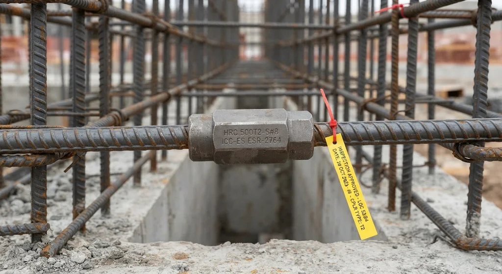
| Traceability | Markings and records available | Missing lot or product identification |
The code, approved documents, and product instructions determine the actual requirements. For HRC 500/510 and HRC 300, ESR-2764 Section 7 describes stamped markings (product designation, bar size, lot number, and “T2”) and labeled packaging; Section 4.3 lists the special inspector’s duties.
⭐ Common Rebar Coupler Sizing and Installation Mistakes
The most common coupler mistakes are using the bar diameter as the coupler OD, assuming one length fits all products, and ignoring grade, classification, and cover.
| Mistake | Corrective action |
|---|---|
| Confusing bar diameter with coupler OD | Use the product OD for cover and spacing checks |
| Assuming universal coupler lengths | Read length from the specific product report |
| Mixing incompatible threads | Use only the approved bar-end and coupler pairing |
| Ignoring reinforcement grade | Check the approved grade list for the bar size |
| Incorrect splice classification | Match Type 1 or Type 2 to the design requirement |
| Insufficient cover or clearance | Measure cover from the coupler outside and check gaps |
| Missing inspection documentation | Keep markings, tags, and inspection records |
⭐ How to Select the Correct Rebar Coupler
To select a rebar coupler, confirm bar size and grade, the required splice type, an evaluated product, its geometry and access, and the engineer’s approval, ending with a specific product and model.
- Confirm the bar designation (see the Rebar Size Chart).
- Verify the steel grade (see the Rebar Grade Chart).
- Identify the required splice classification, Type 1 or Type 2.
- Check coupler geometry: OD, length, cover, and spacing.
- Confirm product evaluation in the current report.
- Check installation access and bar-end preparation.
- Obtain engineer and project approval.
Rebar Coupler Size FAQs
These are the most common questions about rebar coupler sizes, answered with ICC-ES evaluated HRC product dimensions.
What is a rebar coupler?
A rebar coupler is a mechanical splice that joins two reinforcing bars end to end so force passes through the device instead of through overlapping bars. Systems include threaded, upset-threaded, swaged, and bolt-locking types, and each has its own dimensions, approvals, and installation requirements.
What size coupler is used for #4 rebar?
It depends on the product. The HRC 500/510 Xtender coupler for #4 bar is 1.375 in. in outside diameter and about 2.00 in. long, and the HRC 300 coupler is 0.88 in. by 1.75 in. Sizes are product-specific, so check the approved system.
What size coupler fits #5 rebar?
For #5 bar (0.625 in.), the HRC 500/510 coupler is 1.500 in. OD by 2.13 in. long, and the HRC 300 coupler is 1.00 in. by 2.00 in. Other manufacturers differ, so confirm the exact product, grade, and bar-end preparation.
What is the coupler size for #6 rebar?
For #6 bar (0.750 in.), the HRC 500/510 coupler is 1.625 in. OD and 2.38 in. long, and the HRC 300 coupler is 1.13 in. by 2.13 in. These are two documented examples, not universal dimensions for every #6 coupler.
What size coupler is used for #8 rebar?
For #8 bar (1.000 in.), the HRC 500/510 coupler is 2.125 in. OD by 3.13 in. long, and the HRC 300 coupler is 1.50 in. by 3.00 in. The coupler size depends on the manufacturer, and both products also have grade and preparation requirements.
What is the outside diameter of a #8 rebar coupler?
In the HRC 500/510 system the OD is 2.125 in. (53.98 mm), about 2.1 times the 1.000 in. bar. In the HRC 300 system it is 1.50 in. Other manufacturers publish different values, so use the product data for the coupler you specify.
How long is a #8 rebar coupler?
The HRC 500/510 coupler has a typical length of 3.13 in. (79.50 mm) and the HRC 300 coupler is 3.00 in. long. Length is a product dimension and is not a minimum splice length, so check the manufacturer data for the product.
Are rebar coupler dimensions standardized?
No. ACI 318 sets splice strength classes, but coupler outside diameter, length, thread form, and engagement are proprietary to each system and documented in evaluation reports. There is no single universal dimension chart, so use the approved product’s published data.
Can the same coupler join different rebar sizes?
Only if the system is a transition coupler designed for it. Standard couplers are made for one bar size, and state DOT lists show separate transition couplers for size changes such as #8 to #9. Never assume a standard coupler can join two sizes.
Are #4 and 12 mm couplers interchangeable?
No. A #4 bar is 12.7 mm (0.500 in.), while true metric 12 mm bar is a different product under a different standard. ASTM soft-metric #13 labels the same U.S. #4 bar. Do not mix coupler systems between U.S. and true metric bars.
What is a Type 1 rebar coupler?
A Type 1 mechanical splice develops at least 1.25 times the specified yield strength of the bar, as required. For a #8 Grade 60 bar that threshold is 59.25 kips. Type 1 splices have location restrictions in seismic design, so check the adopted ACI provisions.
What is a Type 2 rebar coupler?
A Type 2 mechanical splice meets the Type 1 requirement and also develops the specified tensile strength of the spliced bar. ESR-2764 says the HRC couplers can be used as Type 2 splices, marked “T2”. Type 2 is a performance class, not a larger or stronger-looking coupler.
Are Type 2 couplers required in seismic construction?
Not always. Type 2 splices are used where inelastic cyclic response is expected, such as yielding regions, and ACI 318-19 limits where Type 1 splices may go. The structural system, bar grade, and adopted code decide what is required, so read the structural drawings and project specifications.
Can rebar couplers replace lap splices?
They can be used instead of laps, but not as a fixed-length substitute. A coupler needs product qualification, clearances, bar preparation, and inspection, while lap length comes from separate development and splice provisions. Follow the structural drawings and the engineer’s detail.
Do couplers require a minimum thread engagement?
For some systems yes. In the HRC 300 system the bar must engage at least T, from 0.75 in. for #4 and #5 to 1.13 in. for #8. That value is set by the manufacturer for that system and must not be transferred to other couplers.
Do all threaded couplers require torque tightening?
No. ESR-2764 calls for hand-tightening to a snug fit, with lubricated threads and wrenches if necessary, for the HRC 500/510 and HRC 300 systems, not a torque value. Other systems may specify torque, so follow each product’s approved installation instructions.
How is concrete cover measured around a coupler?
ESR-2764 requires minimum cover and spacing to be measured from the outer surface of the coupler. A #8 HRC 500/510 coupler with 2.00 in. of cover to its surface puts the centerline 3.0625 in. from the face. The 2.00 in. is an example, not a code value.
Can rebar couplers be installed on fixed bars?
Yes, with a positional coupler. The HRC 500/510 is designed so pre-bent and pre-tied bars can be joined without rotating the bars, by threading the male and female components together. Standard threaded couplers that require bar rotation cannot be used on fixed bars.
Are couplers available for #14 and #18 rebar?
Yes for #14: HRC 500/510 covers it (3.500 in. OD, 5.13 in. long). #18 is not in ESR-2764, but other manufacturers list #18 couplers on state DOT approved lists. Verify the product, approved grades, and evaluation for each large-bar coupler.
How do I verify that a rebar coupler is code-compliant?
Check the product’s current ICC-ES report or equivalent approval, confirm the bar size and grade are listed, verify the Type 1 or Type 2 classification and markings, and follow the installation instructions and special inspection. The engineer of record and code official decide acceptance.
Using the Rebar Coupler Size Chart
This rebar coupler size chart gives manufacturer-verified HRC coupler dimensions by bar size, with Type 1 and Type 2, cover, spacing, and inspection context.
Start with the bar size and grade, then confirm the approved product, its OD and length, the splice classification, and the cover and spacing around the coupler. The dimensions here describe named HRC systems, not every rebar coupler, and the adopted code edition and approved drawings govern. For bar data see the Rebar Size Chart, Rebar Grade Chart, and Rebar Area Chart; for conventional splices see the Rebar Lap Splice Chart.
📄 Download Rebar Coupler Size Chart PDF
Use your browser print function to save this page as a print-ready PDF for submittal and inspection binders. Buttons and image placeholders are hidden when printing.
- Coupler dimension chart
- HRC 300 table
- Type 1 and Type 2 summary
- Cover and spacing examples
- Inspection checklist