Footing Size Chart – Width, Depth & Reinforcement Guide
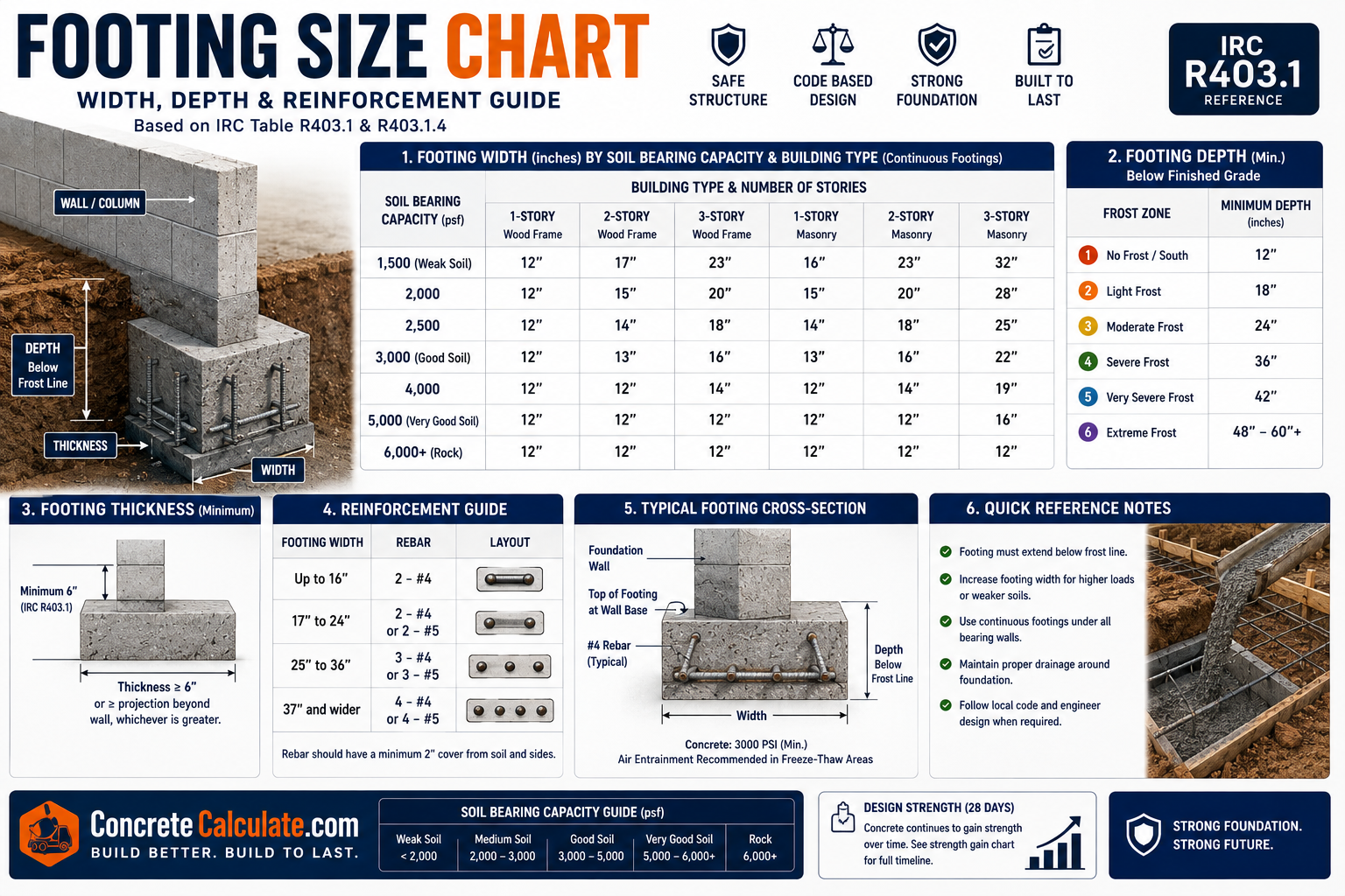
Footing Size Chart
Width, Depth & Reinforcement Guide
The complete footing sizing reference — width, depth, thickness by soil bearing capacity, building type, and frost zone.
 Reviewed by Muhammad Ramzan Babar, PhD Researcher (Plasma Physics) & Calculator Developer — View Profile
⭐ Master Footing Size Chart
Complete reference showing recommended footing widths, depths, thicknesses, and reinforcement for common applications.
How to Read This Chart
Values reflect IRC Table R403.1 prescriptive minimums for conventional light-frame construction. Site-specific soil testing and local code always take precedence. Size your footing with our Concrete Footing Calculator.
| Structure | Width | Thickness | Typical Reinforcement |
|---|---|---|---|
| Garden Shed | 12″–16″ | 4″–6″ | None or fiber mesh |
| Deck Post | 18″–24″ dia. (pier) | Below frost line | None or vertical rebar |
| Garage | 12″–16″ | 6″–8″ | 2x #4 rebar |
| Single-Story House | 12″–15″ | 6″ | 2x #4 rebar |
| Two-Story House | 15″–21″ | 6″–8″ | 2x #4 rebar, #5 on weak soil |
| Retaining Wall | 24″–48″+ | 10″–18″ | #4-#5 rebar, engineer-designed |
| Commercial Building | Engineer-designed | 12″+ | Per structural drawings |
Source: IRC Table R403.1 minimum footing width for conventional light-frame construction [web:254].
⭐ Footing Size by Building Type
Recommended footing dimensions scale with the structure’s expected load.
| Structure | Recommended Footing Size |
|---|---|
| Garden Shed | 12″x12″x4″-6″ pad or perimeter footing |
| Deck | 18″-24″ dia. pier footings, below frost depth |
| Patio Cover | 12″x12″x18″ pad footings at each post |
| Garage | 12″-16″ wide x 6″-8″ thick continuous footing |
| Single-Story House | 12″-15″ wide x 6″ thick continuous footing |
| Two-Story House | 15″-21″ wide x 6″-8″ thick continuous footing |
| Retaining Wall | 24″-48″+ wide, engineer-designed based on wall height |
| Commercial Building | Engineer-designed, typically 18″-36″+ isolated pads |
| Steel Column | 24″x24″x12″+ isolated pad, load-dependent |
Concrete Footing Width Chart
Width scales inversely with soil bearing strength — weaker soil needs a wider footing to spread the same load.
| Load Type | Recommended Width | Typical Reinforcement |
|---|---|---|
| Light residential (1-story) | 12″ | 2x #4 rebar |
| Medium residential (2-story) | 15″-21″ | 2x #4 rebar |
| Heavy residential (3-story) | 17″-32″ | 2x #4-#5 rebar |
| Light commercial | 18″-24″ | Per engineer |
| Heavy commercial/industrial | 24″-48″+ | Per engineer, often double-mat |
Concrete Footing Depth Chart
Depth is primarily driven by frost protection requirements, not load capacity.
| Climate Zone | Recommended Depth |
|---|---|
| Frost-Free/Warm Areas | 12″ minimum |
| Moderate Frost | 18″-30″ |
| Heavy Frost | 36″-48″ |
| Severe Frost (Northern climates) | 48″-60″+ |
Source: IRC Section R403.1.4 frost protection requirements [web:265]. Calculate your local requirement with our Foundation Depth Calculator.
Footing Thickness Chart
Thickness must be at least equal to the footing’s projection beyond the foundation wall, with a 6-inch code minimum.
| Footing Width | Recommended Thickness |
|---|---|
| 12″ | 6″ |
| 15″ | 6″ |
| 18″ | 7″ |
| 21″ | 8″ |
| 24″ | 8″-10″ |
| 32″+ | 10″-12″ |
Source: IRC minimum 6-inch thickness rule with projection-based sizing [web:253].
Continuous Footing Size Chart
Continuous footings run beneath load-bearing and foundation walls, distributing load along the entire wall length.
| Wall Type | Recommended Footing Size |
|---|---|
| Load-Bearing Walls | 12″-21″ wide x 6″-8″ thick |
| Retaining Walls | 24″-48″+ wide, engineer-designed |
| Foundation Walls | 12″-21″ wide x 6″-8″ thick |
| Basement Walls | 16″-24″ wide x 8″-10″ thick |
Isolated (Pad) Footing Size Chart
Isolated footings support a single point load, typically a column, and are sized based on the load and soil bearing capacity.
| Application | Recommended Pad Size |
|---|---|
| Residential Columns | 18″x18″x8″-12″ |
| Steel Columns | 24″x24″x12″-18″ |
| Concrete Columns | 24″x24″x12″-18″ |
| Light Structures | 12″x12″x8″-10″ |
| Heavy Structures | 36″x36″x18″+ (engineer-designed) |
Strip Footing Size Chart
Strip footings are a form of continuous footing commonly used under masonry and boundary walls.
| Wall Type | Recommended Strip Footing Size |
|---|---|
| Masonry Walls | 16″-24″ wide x 8″ thick |
| Reinforced Concrete Walls | 18″-24″ wide x 8″-10″ thick |
| Boundary Walls | 12″-18″ wide x 6″-8″ thick |
Combined Footing Size Chart
Combined footings support two or more columns on a single pad, often used when columns are close together or near a property line.
| Type | Recommended Size Guidance |
|---|---|
| Two-Column Footings | Sized to keep resultant load within middle third of footing; engineer-designed |
| Property-Line Footings | Rectangular/trapezoidal shape to avoid crossing the property line; engineer-designed |
| Offset Footings | Asymmetric shape balancing eccentric loads; engineer-designed |
Combined footings almost always require site-specific engineering due to the complexity of balancing multiple point loads.
⭐ Footing Size by Soil Bearing Capacity
Footing dimensions depend heavily on soil conditions — this is the single most important design variable per IRC Table R403.1.
| Soil Type | Bearing Capacity (psf) | 1-Story Footing Width | 2-Story Footing Width |
|---|---|---|---|
| Rock | ≥4,000 | 12″ | 12″ |
| Dense Gravel | 3,000-4,000 | 12″ | 12″ |
| Sand | 2,000-3,000 | 12″ | 12″-15″ |
| Sandy Clay | 2,000 | 12″ | 15″ |
| Clay | 1,500-2,000 | 12″-16″ | 15″-21″ |
| Soft Clay | 1,000-1,500 | 16″+ | 21″+ |
| Filled Soil | Variable/unverified | Requires soil test | Requires soil test |
Source: IRC Table R403.1 minimum footing width by soil load-bearing value [web:252][web:254]. Check your soil with our Soil Bearing Capacity Calculator.
Footing Size by Construction Application
Practical sizing guidance across common project types.
| Application | Recommended Footing Size |
|---|---|
| House Foundations | 12″-21″ wide x 6″-8″ thick |
| Deck Posts | 18″-24″ dia. pier, below frost line |
| Fence Posts | 8″-12″ dia. x 24″-36″ deep |
| Retaining Walls | 24″-48″+ wide, engineer-designed |
| Garage Foundations | 12″-16″ wide x 6″-8″ thick |
| Industrial Columns | 36″+ isolated pad, engineer-designed |
| Pole Barns | 24″-36″ dia. pier or continuous footing per span |
Footing Size by Column Size
Isolated pad footings are typically sized at 2-3 times the column width per side, adjusted for load and soil bearing.
| Column Size | Recommended Pad Footing |
|---|---|
| 4″x4″ wood post | 12″x12″x8″ |
| 6″x6″ wood post | 18″x18″x10″ |
| 8″ steel column | 24″x24″x12″ |
| 10″-12″ concrete column | 30″x30″x15″ |
| 14″+ heavy column | 36″x36″x18″+ (engineer-designed) |
Footing Reinforcement Chart
Reinforcement requirements scale with footing width and applicable soil/seismic conditions.
| Footing Size | Recommended Rebar | Spacing/Number of Bars |
|---|---|---|
| 12″ wide | #4 rebar | 2 continuous bars |
| 15″-18″ wide | #4 rebar | 2-3 continuous bars |
| 21″-24″ wide | #4-#5 rebar | 3 continuous bars |
| 24″x24″ pad | #4 rebar grid | 12″ o.c. each direction |
| 36″x36″+ pad | #5 rebar grid | 8″-12″ o.c. each direction |
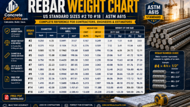
Cross-check with our Rebar Size Chart and confirm whether reinforcement is required in our Does Concrete Need Rebar guide.
Footing Cover Requirements
Footings poured against earth require more concrete cover than formed surfaces to protect rebar from soil moisture.
| Location | Minimum Cover |
|---|---|
| Bottom Cover (cast against earth) | 3″ |
| Side Cover (cast against earth) | 3″ |
| Top Cover | 1.5″-2″ |
For complete cover requirements across all concrete elements, see our Concrete Cover Chart.
Footing Concrete Strength Chart
Concrete strength for footings should match exposure conditions and structural demand.
| Strength | Recommended Use |
|---|---|
| 3000 PSI | Standard residential footings in mild climates |
| 3500 PSI | Residential footings in freeze-thaw climates |
| 4000 PSI | Commercial/multi-story footings, higher loads |
| 5000 PSI | Heavy industrial or engineered structural footings |
Learn more in our Concrete PSI Guide.
Footing Excavation Size Chart
Excavation must be wider than the footing itself to accommodate formwork and worker access.
| Footing Width | Recommended Excavation Width |
|---|---|
| 12″ | 18″-24″ (formwork + working space) |
| 18″ | 24″-30″ |
| 24″ | 30″-36″ |
| 36″+ | Width + 12″-18″ per side for access |
Plan your dig with our Foundation Excavation Calculator.
Frost Depth vs Footing Depth Chart
Footings must always be placed below the local frost line to prevent frost heave damage.
| Region | Typical Frost Depth | Required Footing Depth |
|---|---|---|
| Warm Regions (FL, HI, coastal south) | 0″-12″ | 12″ minimum |
| Moderate Frost Zones (mid-Atlantic, Pacific NW) | 18″-30″ | 18″-30″ |
| Cold Climates (Midwest, New England) | 36″-48″ | 42″-48″ |
| Severe Frost Areas (MN, WI, ME, AK) | 60″+ | 60″+ |
Source: IRC Section R403.1.4 frost line requirements by region [web:265][web:262].
⭐ Residential Foundation Footing Guide
Footing design varies significantly by foundation type, even for the same house.
Slab-on-Grade
Monolithic or turned-down footing at slab perimeter, typically 12″-24″ wide
Crawl Space
Continuous perimeter footing, 12″-18″ wide, supporting short foundation walls
Basement Foundation
Deeper continuous footing, 16″-24″ wide, below frost line supporting full-height walls
Deck Footings
Individual pier footings, 18″-24″ diameter, spaced per post layout
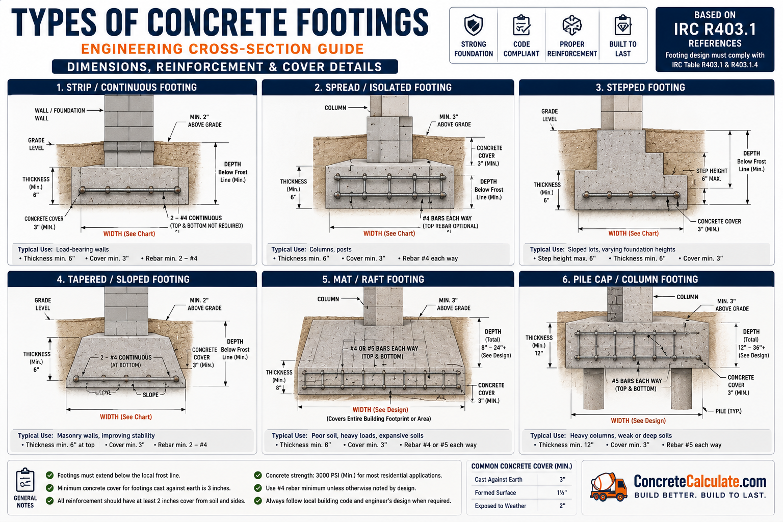
⭐ Visual Footing Size Guide
Engineering diagrams showing the six most common footing types and their key dimensions.
Strip Footing
Continuous strip beneath a wall; width & depth labeled
Isolated Footing
Single square/rectangular pad beneath one column
Combined Footing
Single pad supporting two columns, rebar placement varies by load
Continuous Footing
Runs beneath entire foundation wall length
Stepped Footing
Steps down a slope, keeping each section level and below frost depth
Sloped Footing
Continuous incline following slope grade for hillside foundations
Common Footing Design Mistakes
Errors that compromise foundation performance regardless of concrete quality.
Undersized footings
Footings too narrow for the soil bearing capacity cause excessive settlement and cracking over time.
Poor soil preparation
Failing to compact or remove organic material beneath the footing leads to uneven settlement.
Incorrect reinforcement
Missing or undersized rebar reduces the footing’s ability to resist bending stresses from uneven loads.
Insufficient concrete cover
Less than 3 inches of cover against earth allows moisture and corrosion to reach the rebar prematurely.
Footings above frost depth
Shallow footings in cold climates are vulnerable to frost heave, which can crack and shift the entire foundation.
Poor drainage
Water pooling around or beneath footings weakens soil bearing capacity and increases frost heave risk.
Uneven bearing surface
Footings poured on sloped or inconsistent soil can settle unevenly, causing structural cracking above.
Contractor Worked Examples
Real-world footing sizing decisions for common job scenarios.
Deck Footing
Garage Foundation
House Foundation
Retaining Wall
Steel Column Base
Pole Barn Foundation
Frequently Asked Questions
📥 Download Footing Size Chart PDF
Use your browser’s print function to instantly save this page as a PDF — a printable engineering reference with footing dimension tables, soil bearing capacity guide, reinforcement recommendations, diagrams, and a quick field reference.