Pipe Fitting Dimensions Chart: Elbows, Tees & Reducers
Center-to-end and end-to-end dimensions for butt-weld elbows, tees, reducers, and caps, with guidance on threaded, socket-weld, PVC, copper, and HDPE fittings.
 Reviewed by Muhammad Ramzan Babar, PhD Researcher (Plasma Physics) & Calculator Developer. View Profile
⭐ Pipe Fitting Dimensions Chart
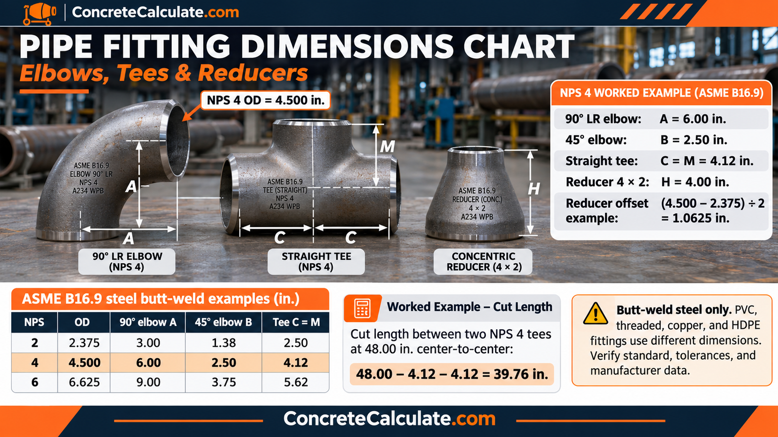
A pipe fitting dimensions chart gives standard center-to-end lengths by nominal pipe size. For ASME B16.9 butt-weld steel fittings at NPS 4, a 90° long-radius elbow measures A = 6.00 in., a 45° elbow measures B = 2.50 in., and a straight tee measures C = M = 4.12 in.
ASME B16.9 Elbow and Tee Dimensions
| Nominal pipe size, NPS (in.) | Actual outside diameter (in.) | 90° elbow center-to-end A (in.) | 45° elbow center-to-end B (in.) | Tee center-to-end C = M (in.) |
|---|---|---|---|---|
| 1/2 | 0.840 | 1.50 | 0.62 | 1.00 |
| 3/4 | 1.050 | 1.50 | 0.75 | 1.12 |
| 1 | 1.315 | 1.50 | 0.88 | 1.50 |
| 1¼ | 1.660 | 1.88 | 1.00 | 1.88 |
| 1½ | 1.900 | 2.25 | 1.12 | 2.25 |
| 2 | 2.375 | 3.00 | 1.38 | 2.50 |
| 2½ | 2.875 | 3.75 | 1.75 | 3.00 |
| 3 | 3.500 | 4.50 | 2.00 | 3.38 |
| 4 | 4.500 | 6.00 | 2.50 | 4.12 |
| 5 | 5.563 | 7.50 | 3.12 | 4.88 |
| 6 | 6.625 | 9.00 | 3.75 | 5.62 |
| 8 | 8.625 | 12.00 | 5.00 | 7.00 |
| 10 | 10.750 | 15.00 | 6.25 | 8.50 |
| 12 | 12.750 | 18.00 | 7.50 | 10.00 |
Source: nominal long-radius elbow, 45° elbow, and straight-tee dimensions from the ASME B16.9 tables (ASME B16.9-2024 is the current edition); outside diameters are standard inch-series steel pipe values. Rounded decimal-inch presentation follows customary source tables.
✓ Checked against ASME B16.9 metric table text (2003 edition) and published inch tables from fitting manufacturers, November 2026Butt-weld fittings only
These are nominal dimensions for ASME B16.9 wrought butt-weld fittings. They are not generic dimensions for PVC, threaded iron, socket-weld, copper solder-joint, press-connect, or HDPE fittings. Verify manufacturing tolerances, the specified standard edition, and product requirements.
How to Read the Chart
- A is the 90° elbow center-to-end, B is the 45° elbow center-to-end, and C = M is the straight-tee run and branch center-to-end.
- All three measure from the theoretical centerline intersection to the end face. B is not the elbow envelope or its centerline radius.
- The same nominal size gives different values for each fitting, so matching NPS does not mean matching length.
For full NPS-to-OD data see the Pipe Outside Diameter Chart; for wall thickness, see the Pipe Wall Thickness Chart.
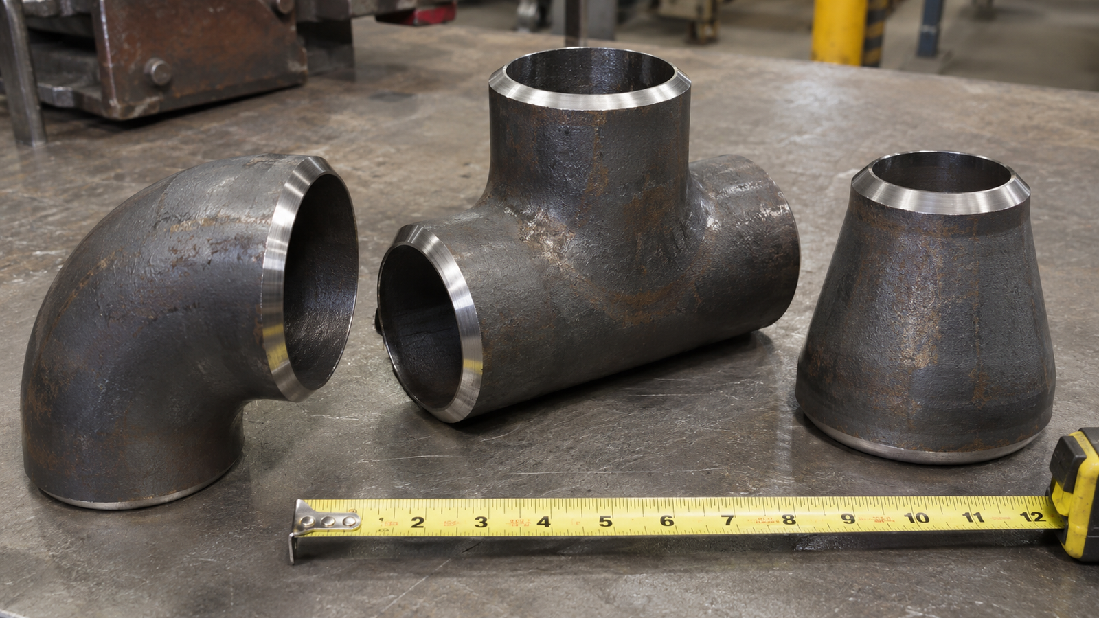
What Are Pipe Fitting Dimensions?
Pipe fitting dimensions are the standardized lengths, diameters, and connection details of a fitting, such as the 6.00 in. center-to-end of an NPS 4 long-radius elbow, and they depend on shape and connection system.
- Nominal pipe size: a size name, not a measured dimension.
- Actual outside diameter: the real pipe OD the fitting connects to.
- Center-to-end: from the centerline intersection to a connection face.
- End-to-end: between the two outer connection faces.
- Socket depth: how far pipe inserts into a socket or cup.
- Overall envelope: the space the fitting body occupies.
Central principle
Nominal pipe size does not set the outside envelope, center-to-end dimension, or installed length of every fitting. The shape, the connection method, and the governing standard decide it.
NPS vs. Actual Pipe Outside Diameter
NPS 4 steel pipe has a 4.500 in. outside diameter, so nominal pipe size is a name and the actual OD, not the name, must match the fitting.
| Nominal size (in.) | Steel pipe OD (NPS) | PVC pressure pipe OD (IPS) | Copper water tube OD |
|---|---|---|---|
| 1/2 | 0.840 | 0.840 | 0.625 |
| 3/4 | 1.050 | 1.050 | 0.875 |
| 1 | 1.315 | 1.315 | 1.125 |
| 1½ | 1.900 | 1.900 | 1.625 |
| 2 | 2.375 | 2.375 | 2.125 |
| 3 | 3.500 | 3.500 | 3.125 |
| 4 | 4.500 | 4.500 | 4.125 |
| 6 | 6.625 | 6.625 | 6.125 |
| 8 | 8.625 | 8.625 | 8.125 |
Steel NPS outside diameters are standard inch-series values; PVC pressure pipe and fittings in the Schedule 40 and 80 standards use the IPS outside diameter system; copper water tube outside diameter is the nominal size plus 1/8 in. (ASTM B88).
✓ Checked against standard NPS outside diameters and ASTM B88 copper tube references, November 2026A 2 in. steel fitting connects to 2.375 in. OD pipe, but 2 in. copper tube is 2.125 in. OD, so the two are not interchangeable. See the Pipe Outside Diameter Chart, Pipe Inside Diameter Chart, Pipe Schedule Chart, and Copper Pipe Size Chart.
⭐ How to Measure Pipe Fittings
To measure a pipe fitting, identify the fitting family, then use its own reference point: center-to-end for elbows and tees, end-to-end for reducers, and socket or thread engagement for plumbing fittings.
| Measurement | Definition | Typical use |
|---|---|---|
| Center-to-end | From the defined centerline intersection to a connection face | 90° and 45° elbows, tees |
| Center-to-center | Between two defined fitting or bend centers | 180° returns, layout |
| End-to-end | Between the two outer connection end planes | Reducers, some couplings |
| Overall envelope | Physical space of the body, socket, or thread | Clearance and routing |
Terminology follows ASME B16.9 figures for butt-weld fittings. Other fitting systems define their own reference points.
Center-to-End, Center-to-Center, and End-to-End
Each is a separate measurement. Overall envelope must not be assumed equal to a center-to-end value.
Socket and Thread Engagement
Socket depth and thread engagement are set by the product standard or manufacturer, not by the butt-weld tables.
| Connection | Key dimensional issue |
|---|---|
| Butt-weld | End-to-center geometry, weld-end OD, wall, and end preparation |
| Threaded | NPT thread engagement, fitting face, and insertion |
| Socket-weld | Socket depth, pipe insertion, and weld fit-up |
| PVC solvent-weld socket | Socket dimensions, pipe insertion, and joint preparation |
| Copper solder | Cup depth and tube engagement |
| Press-connect | Specified insertion and press-system compatibility |
| HDPE fusion | Fusion system, pipe OD, and connection geometry |
| Flanged | Face-to-face and flange connection dimensions |
Do not collapse these into one universal insertion-depth chart.
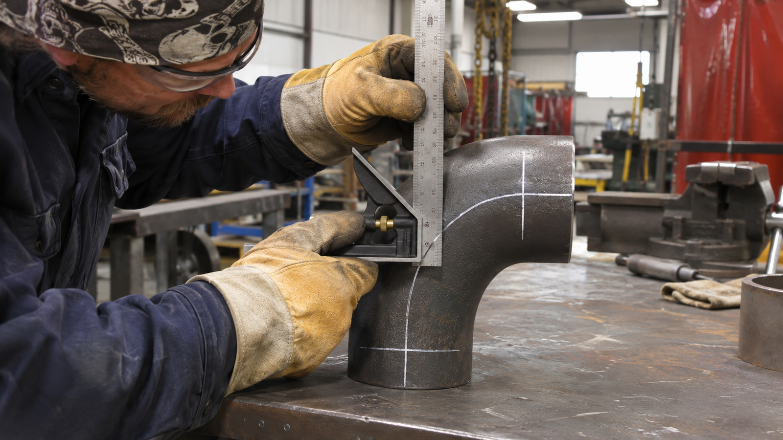
⭐ 90° Long-Radius Elbow Dimensions
A 90° long-radius butt-weld elbow has center-to-end A equal to 1.5 times NPS from NPS 1 up, so an NPS 4 elbow measures 6.00 in. (152 mm).
| NPS (in.) | Published A (in.) | Published A (mm) | 1.5 × NPS (in.) | vs. the 1.5D rule |
|---|---|---|---|---|
| 1/2 | 1.50 | 38 | 0.75 | exception |
| 3/4 | 1.50 | 38 | 1.12 | exception |
| 1 | 1.50 | 38 | 1.50 | matches |
| 1¼ | 1.88 | 48 | 1.88 | matches |
| 1½ | 2.25 | 57 | 2.25 | matches |
| 2 | 3.00 | 76 | 3.00 | matches |
| 2½ | 3.75 | 95 | 3.75 | matches |
| 3 | 4.50 | 114 | 4.50 | matches |
| 4 | 6.00 | 152 | 6.00 | matches |
| 5 | 7.50 | 190 | 7.50 | matches |
| 6 | 9.00 | 229 | 9.00 | matches |
| 8 | 12.00 | 305 | 12.00 | matches |
| 10 | 15.00 | 381 | 15.00 | matches |
| 12 | 18.00 | 457 | 18.00 | matches |
Source: ASME B16.9 long-radius elbow table (mm column read from the 2003 edition text; inch column from the published inch tables). The 1.5D rule applies from NPS 1 up; NPS 1/2 and 3/4 keep A = 1.50 in.
✓ Checked against ASME B16.9 metric table text (2003 edition) and published inch tables from fitting manufacturers, November 2026Bend geometry and minimum bend radii are covered in the Pipe Bend Radius Chart. Here the focus is the center-to-end value for layout.
⭐ 90° Short-Radius Elbow Dimensions
A 90° short-radius steel elbow has center-to-end A equal to 1.0 times NPS, so at NPS 4 it measures 4.00 in., 2.00 in. less than the 6.00 in. long-radius elbow.
| NPS (in.) | Long-radius A (in.) | Short-radius A (in.) | Difference (in.) |
|---|---|---|---|
| 1 | 1.50 | 1.00 | 0.50 |
| 1¼ | 1.88 | 1.25 | 0.63 |
| 1½ | 2.25 | 1.50 | 0.75 |
| 2 | 3.00 | 2.00 | 1.00 |
| 3 | 4.50 | 3.00 | 1.50 |
| 4 | 6.00 | 4.00 | 2.00 |
| 6 | 9.00 | 6.00 | 3.00 |
| 8 | 12.00 | 8.00 | 4.00 |
| 10 | 15.00 | 10.00 | 5.00 |
| 12 | 18.00 | 12.00 | 6.00 |
Source: ASME B16.9-2024; short-radius values equal 1.0 × NPS (NPS 1 and up) and were checked against published fitting tables (mm: 25, 32, 38, 51, 76, 102, 152, 203, 254, 305). Differences are calculated.
✓ Checked against ASME B16.9 metric table text (2003 edition) and published inch tables from fitting manufacturers, November 2026- The short-radius chart starts at NPS 1; do not add NPS 1/2 or 3/4 with the simple 1D rule.
- Compactness does not establish suitability: pressure loss, erosion, service, and material may control the choice.
NPS 4 fittings share an OD but not a length
These are source-published reference dimensions, not estimates from pipe diameter. A smaller center-to-end does not make a short-radius elbow an acceptable hydraulic or mechanical substitute.
45° Elbow Dimensions
A 45° long-radius butt-weld elbow has center-to-end B of 2.50 in. at NPS 4, a straight distance from the centerline intersection to the end face, not an arc length.
| NPS (in.) | Published B (in.) | Published B (mm) | 90° elbow A (in.) |
|---|---|---|---|
| 1/2 | 0.62 | 16 | 1.50 |
| 3/4 | 0.75 | 19 | 1.50 |
| 1 | 0.88 | 22 | 1.50 |
| 1¼ | 1.00 | 25 | 1.88 |
| 1½ | 1.12 | 29 | 2.25 |
| 2 | 1.38 | 35 | 3.00 |
| 2½ | 1.75 | 44 | 3.75 |
| 3 | 2.00 | 51 | 4.50 |
| 4 | 2.50 | 64 | 6.00 |
| 5 | 3.12 | 79 | 7.50 |
| 6 | 3.75 | 95 | 9.00 |
| 8 | 5.00 | 127 | 12.00 |
| 10 | 6.25 | 159 | 15.00 |
| 12 | 7.50 | 190 | 18.00 |
Source: ASME B16.9 long-radius elbow table (mm from the 2003 edition text; inches from published inch tables).
✓ Checked against ASME B16.9 metric table text (2003 edition) and published inch tables from fitting manufacturers, November 2026Why the catalog B differs from a tangent calculation
Use the ASME dimension for manufactured fittings. Use circular-arc geometry only for clearly labeled fabrication calculations.
180° Return Bend Dimensions
A 180° long-radius return bend uses center-to-center O, which equals twice the 90° elbow A, so an NPS 4 return is 12.00 in. center-to-center.
| NPS (in.) | 90° LR elbow A (in.) | Return center-to-center O = 2A (in.) |
|---|---|---|
| 1 | 1.50 | 3.00 |
| 1½ | 2.25 | 4.50 |
| 2 | 3.00 | 6.00 |
| 3 | 4.50 | 9.00 |
| 4 | 6.00 | 12.00 |
| 6 | 9.00 | 18.00 |
| 8 | 12.00 | 24.00 |
| 10 | 15.00 | 30.00 |
| 12 | 18.00 | 36.00 |
Source: ASME B16.9 long-radius returns, where O equals 2 × A (NPS 2, 6, and 12 values 6.00, 18.00, and 36.00 in. confirmed in published tables). Back-to-face K is a separate dimension; for NPS 6 it is 313 mm. NPS 1/2 and 3/4 follow stepped radii and are not listed.
✓ Checked against published B16.9 return tables at NPS 2, 6, and 12; other rows follow O = 2A, November 2026Long-radius and short-radius returns differ. Keep bend-radius theory on the Pipe Bend Radius Chart.
⭐ Straight Tee Dimensions
For a standard straight tee the run and branch center-to-end values are equal, so an NPS 2 tee has C = M = 2.50 in. and an overall run of about 5.00 in.
| NPS (in.) | Run center-to-end C (in.) | Branch center-to-end M (in.) | Calculated overall run 2C (in.) |
|---|---|---|---|
| 1 | 1.50 | 1.50 | 3.00 |
| 1½ | 2.25 | 2.25 | 4.50 |
| 2 | 2.50 | 2.50 | 5.00 |
| 3 | 3.38 | 3.38 | 6.76 |
| 4 | 4.12 | 4.12 | 8.24 |
| 6 | 5.62 | 5.62 | 11.24 |
| 8 | 7.00 | 7.00 | 14.00 |
| 10 | 8.50 | 8.50 | 17.00 |
| 12 | 10.00 | 10.00 | 20.00 |
Source: ASME B16.9 straight tee tables. The 2C column is calculated from the displayed value and is not a separately published ASME overall length.
✓ Checked against ASME B16.9 metric table text (2003 edition) and published inch tables from fitting manufacturers, November 2026Rounding caution
An NPS 4 tee is tabulated at 105 mm (4.12 in.). Doubling the displayed inch value gives 8.24 in., while doubling the metric value gives 210 mm (about 8.27 in.). The approved drawing and the governing unit system control, and 2C should not be treated as a published overall length.
Reducing Tee Dimensions
A reducing tee keeps the run C of its run size but a shorter branch M, so a 4 × 2 tee has C = 105 mm and M = 89 mm, unlike an equal NPS 4 tee.
| Run × branch (NPS) | Run OD (in.) | Branch OD (in.) | Run C (mm) | Branch M (mm) | C converted (in.) | M converted (in.) |
|---|---|---|---|---|---|---|
| 2 × 1 | 2.375 | 1.315 | 64 | 51 | 2.52 | 2.01 |
| 3 × 2 | 3.500 | 2.375 | 86 | 76 | 3.39 | 2.99 |
| 4 × 2 | 4.500 | 2.375 | 105 | 89 | 4.13 | 3.50 |
| 4 × 3 | 4.500 | 3.500 | 105 | 98 | 4.13 | 3.86 |
| 6 × 4 | 6.625 | 4.500 | 143 | 130 | 5.63 | 5.12 |
| 8 × 6 | 8.625 | 6.625 | 178 | 168 | 7.01 | 6.61 |
| 10 × 8 | 10.750 | 8.625 | 216 | 203 | 8.50 | 7.99 |
| 12 × 10 | 12.750 | 10.750 | 254 | 241 | 10.00 | 9.49 |
Source: ASME B16.9 reducing-outlet tee table (metric values), as published by fitting manufacturers. Inch columns are conversions of the metric values, so the standard’s own inch table may differ in the last digit (for example 4.12 in. for NPS 4 C). M is recommended, not required, for run sizes NPS 14 and larger.
✓ Checked against published B16.9 reducing-tee metric tables, November 2026Equal-tee dimensions cannot be assumed for reducing tees: for the 4 × 2 case above, M is 16 mm shorter than C.
⭐ Concentric Reducer Dimensions
A concentric reducer shares one axis at both ends and has end-to-end H set by the large end, so both 4 × 2 and 4 × 3 reducers measure 4.00 in.
| Reducer size, large × small (NPS) | Large-end OD (in.) | Small-end OD (in.) | End-to-end H (in.) | End-to-end H (mm) |
|---|---|---|---|---|
| 1 × 1/2 | 1.315 | 0.840 | 2.00 | 51 |
| 2 × 1 | 2.375 | 1.315 | 3.00 | 76 |
| 3 × 2 | 3.500 | 2.375 | 3.50 | 89 |
| 4 × 2 | 4.500 | 2.375 | 4.00 | 102 |
| 4 × 3 | 4.500 | 3.500 | 4.00 | 102 |
| 6 × 4 | 6.625 | 4.500 | 5.50 | 140 |
| 8 × 6 | 8.625 | 6.625 | 6.00 | 152 |
| 10 × 8 | 10.750 | 8.625 | 7.00 | 178 |
| 12 × 10 | 12.750 | 10.750 | 8.00 | 203 |
Source: ASME B16.9 reducer table (metric values checked in published manufacturer tables; H is set by the large-end size and is the same for concentric and eccentric reducers).
✓ Checked against ASME B16.9 metric table text (2003 edition) and published inch tables from fitting manufacturers, November 2026The cited H values are the same for 4 × 2 and 4 × 3, but the small-end diameters and profiles differ. Do not assume every manufacturer-specific reducer has an identical length.
⭐ Eccentric Reducer Dimensions
An eccentric reducer has the same end-to-end H as a concentric reducer of the same size, but its end centerlines are offset, by 1.0625 in. for a 4 × 2 on an idealized basis.
| Reducer size (NPS) | Large-end OD D_L (in.) | Small-end OD D_S (in.) | Offset e (in.) |
|---|---|---|---|
| 1 × 1/2 | 1.315 | 0.840 | 0.2375 |
| 2 × 1 | 2.375 | 1.315 | 0.5300 |
| 3 × 2 | 3.500 | 2.375 | 0.5625 |
| 4 × 2 | 4.500 | 2.375 | 1.0625 |
| 4 × 3 | 4.500 | 3.500 | 0.5000 |
| 6 × 4 | 6.625 | 4.500 | 1.0625 |
| 8 × 6 | 8.625 | 6.625 | 1.0000 |
| 10 × 8 | 10.750 | 8.625 | 1.0625 |
| 12 × 10 | 12.750 | 10.750 | 1.0000 |
Calculated from standard outside diameters. Idealized geometry only; the manufactured profile, orientation, and tolerances follow the specified fitting.
✓ Calculated from verified dimensions, arithmetic checked, November 2026Offset of a 4 × 2 eccentric reducer
An eccentric reducer shifts the centerline; a concentric reducer keeps both ends coaxial. H is 4.00 in. for both types.
Orientation matters for service: flat side up is commonly used where a high point could trap vapor, and flat side down where a horizontal line must drain. The piping design controls.
Pipe Cap and Coupling Dimensions
A butt-weld cap uses overall length E, such as 3.50 in. at NPS 6, while couplings and threaded caps follow other standards, so no single coupling dimension chart applies.
| NPS (in.) | Cap length E (in.) | Cap length E (mm) |
|---|---|---|
| 2 | 1.50 | 38.10 |
| 6 | 3.50 | 88.90 |
| 12 | 6.00 | 152.40 |
Source: ASME B16.9 cap table, shown for the sizes confirmed in published tables. E applies to standard walls; thicker walls use a longer dimension (E1; for NPS 6 it is 102 mm versus 89 mm). Use the full table for other sizes.
✓ Checked against published B16.9 cap values at NPS 2, 6, and 12, November 2026| Fitting | Reference dimension | Where it comes from |
|---|---|---|
| Butt-weld cap | Overall length E (and E1 for thick walls) | ASME B16.9 |
| Threaded cap or coupling | Body length and thread engagement | ASME B16.3 or B16.11, per product |
| Socket-weld coupling | Overall length and socket depth | ASME B16.11 |
| PVC socket coupling | Socket depth and body length | ASTM D2466 and the manufacturer |
| Copper coupling | Cup depth and overall length | ASME B16.22 and the manufacturer |
There is no universal coupling dimension chart. Each fitting family has its own standard or manufacturer table.
⭐ ASME B16.9 Butt-Weld Fitting Standards
ASME B16.9-2024 covers factory-made wrought butt-weld fittings from NPS 1/2 through 48, including dimensions, tolerances, ratings, testing, and markings, and short-radius elbows are now part of it.
| Material and fitting type | Applicable standard | What must be checked |
|---|---|---|
| Carbon or stainless wrought butt-weld | ASME B16.9-2024 | OD, center-to-end, end-to-end, wall, bevel, tolerances |
| Forged steel socket-weld | ASME B16.11-2021 | Socket dimensions, fitting class, joint details |
| Forged steel threaded | ASME B16.11-2021 | Threads, engagement, class |
| Malleable iron threaded | ASME B16.3-2021 | Center-to-end, class, thread, material |
| Wrought copper solder-joint | ASME B16.22-2021 | Tube OD, cup diameter and depth |
| Cast copper alloy solder-joint | ASME B16.18-2021 | Fitting dimensions, solder-joint details |
| Copper press-connect | ASME B16.51-2021 | Manufacturer-specific installation and insertion data |
| PVC Schedule 40 pressure | ASTM D2466-24 | IPS socket fitting geometry |
| PVC Schedule 80 pressure | ASTM D2467-24 | Socket fitting dimensions and tolerances |
| CPVC pressure | ASTM F438 / F439 (per product) | CPVC product class and dimensions |
| HDPE butt-fusion and electrofusion | Applicable ASTM or AWWA standard plus manufacturer | OD, DR, fitting length, fusion allowance |
ASME lists B16.9-2024 (issued October 2024, NPS 1/2 through 48) as the current edition; other editions are as stated in the approved outline. The standards have different scopes and cannot be merged into one dimensions table.
✓ ASME B16.9-2024 edition and scope confirmed on asme.org; other edition years per outline, November 2026Fabricated laterals and similar fittings made with intersection welds are treated as pipe fabrication and are outside B16.9. Fittings may also be made to special dimensions by agreement between manufacturer and purchaser.
Forged Socket-Weld Fitting Dimensions
ASME B16.11 socket-weld fittings use minimum socket depths such as 9.5 mm at NPS 1/2 and 12.5 mm at NPS 3/4 to 1½, with Class 3000, 6000, and 9000 designations.
| NPS (in.) | Minimum socket depth J (mm) | Minimum socket depth J (in., approx.) |
|---|---|---|
| 1/2 | 9.5 | 0.375 |
| 3/4 to 1½ | 12.5 | 0.50 |
| 2 | 16.0 | 0.63 |
Source: ASME B16.11-2021 values as published in fitting-manufacturer tables of B16.11 dimensions (Class 3000 shown). Inch values are conversions. Socket bore diameters and wall thicknesses vary by class; use the standard.
✓ Checked against published B16.11 tables, November 2026The class numbers are designations, not simple psi values. The pipe insertion depth, the required weld gap, and the assembly sequence come from the governing piping code and welding procedure. Verify against ASME B16.11-2021.
Threaded Pipe Fitting Dimensions
Threaded fittings follow ASME B16.3 (malleable iron, Classes 150 and 300) or B16.11 (forged steel), with NPT thread engagement, not butt-weld center-to-end values.
| Feature | ASME B16.3 malleable iron | ASME B16.11 forged steel |
|---|---|---|
| Classes | 150 and 300 | Own class system (threaded and socket-weld) |
| Typical material | Malleable iron | Forged steel |
| Dimensions | Center-to-end, thread, and class-specific | Body dimensions, threads, tolerances |
| Thread | NPT | NPT |
| Pressure basis | Class and temperature rules of B16.3 | Class and rules of B16.11 |
Sources: ASME B16.3-2021 and ASME B16.11-2021. Threaded fitting dimensions must not be taken from butt-weld tables.
For thread dimensions see the NPT Thread Chart and Pipe Thread Chart; for material-specific pipe, see the Black Iron Pipe Size Chart and Galvanized Pipe Size Chart.
PVC Schedule 40 Fitting Dimensions
ASTM D2466 sets PVC Schedule 40 socket geometry, such as a 0.875 in. minimum socket length for a 1 in. fitting, but not one face-to-center dimension, so steel butt-weld values do not apply.
| Nominal size (in.) | Socket entrance diameter A (in.) | Socket bottom diameter B (in.) | Minimum socket length C (in.) |
|---|---|---|---|
| 1/2 | 0.848 | 0.836 | 0.688 |
| 3/4 | 1.058 | 1.046 | 0.719 |
| 1 | 1.325 | 1.310 | 0.875 |
| 1¼ | 1.670 | 1.655 | 0.938 |
| 1½ | 1.912 | 1.894 | 1.094 |
Source: ASTM D2466-24 socket table as published in the ASTM D2466-2013 text and a manufacturer catalog (tolerance ±0.004 in. on A and B for 1/2 to 3/4, ±0.005 in. for 1 to 1¼, ±0.006 in. for 1½). The 2024 edition was not read. Body and face-to-center dimensions are manufacturer-specific.
✓ Checked against ASTM D2466-2013 table text and a published manufacturer socket table; confirm in D2466-24, November 2026A 2 in. PVC socket elbow must not be assumed to match an NPS 2 steel butt-weld elbow. Use the manufacturer catalog for elbows, tees, couplings, reducers, and adapters, and the PVC Pipe Size Chart for pipe dimensions.
PVC Schedule 80 and CPVC Fitting Dimensions
PVC Schedule 80 fittings follow ASTM D2467-24 and CPVC fittings follow ASTM F438 or F439, so their socket and body dimensions differ from Schedule 40 PVC and from steel.
| Product | Standard | What differs from Schedule 40 PVC |
|---|---|---|
| PVC Schedule 80 pressure | ASTM D2467-24 | Socket dimensions, tolerances, and thicker body walls |
| CPVC Schedule 40 | ASTM F438 | Product class and dimensions |
| CPVC Schedule 80 | ASTM F439 | Product class and dimensions |
| CPVC tube-size (CTS) | Product standard | Different OD system from IPS |
Sources: ASTM D2467-24 and ASTM D2466 text noting that Schedule 40 CPVC sockets moved to F438. No CPVC dimensions are shown; use the exact product family.
Fitting pressure ratings and pipe dimensions are on other pages: see the Pipe Pressure Rating Chart, Schedule 80 Pipe Chart, and CPVC Pipe Size Chart.
Copper Solder-Joint and Press-Connect Fitting Dimensions
Copper fittings are sized to copper tube, whose actual OD is the nominal size plus 1/8 in. (0.625 in. for 1/2), so copper fitting dimensions cannot use steel NPS values.
| Nominal copper size (in.) | Actual OD (in.) | Steel NPS OD, same name (in.) |
|---|---|---|
| 1/2 | 0.625 | 0.840 |
| 3/4 | 0.875 | 1.050 |
| 1 | 1.125 | 1.315 |
| 1½ | 1.625 | 1.900 |
| 2 | 2.125 | 2.375 |
Copper water tube OD is the nominal size plus 1/8 in. Fitting standards: ASME B16.22-2021 (wrought solder-joint) and ASME B16.51-2021 (press-connect). Cup depth and press insertion depth are product-specific and are not listed.
✓ Checked against ASTM B88 tube dimensions as published, November 2026A fitting listed to a common standard does not justify swapping one manufacturer’s press insertion depth for another’s. Check jaw and tool compatibility and installation clearance. See the Copper Pipe Size Chart.
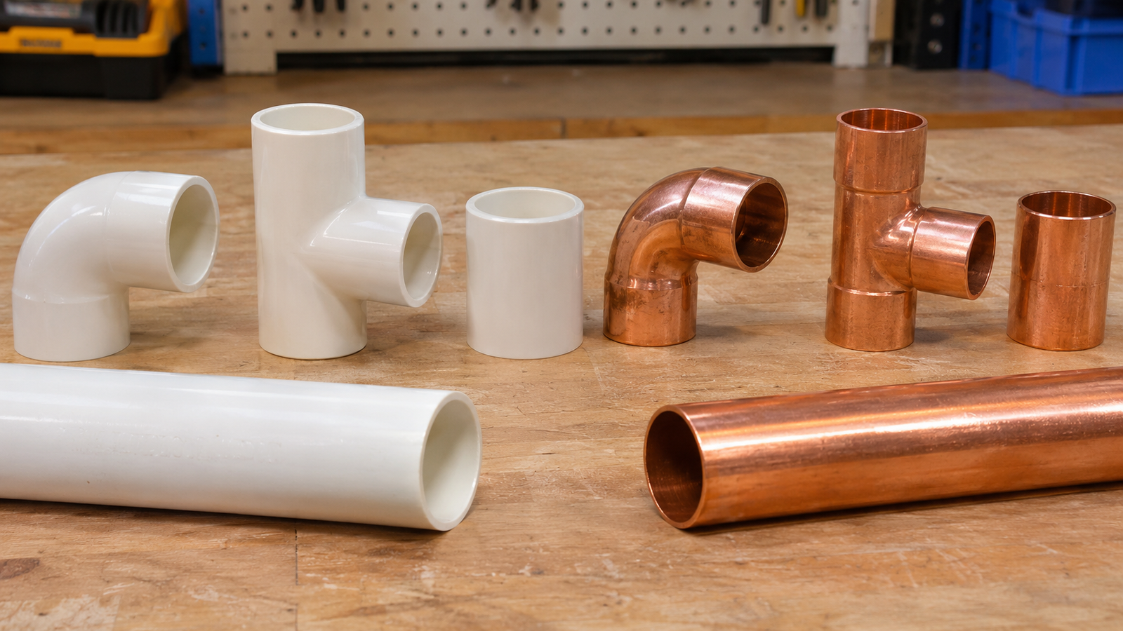
HDPE Fitting Dimensions and SDR Compatibility
HDPE fitting dimensions depend on the OD system (IPS or DIPS), the DR or SDR, and the fusion or mechanical connection, so they come from the product standard and manufacturer, not from steel tables.
- Butt-fusion fittings, electrofusion couplings, and mechanical transitions each have different lengths and fusion allowances.
- IPS and DIPS OD systems are not interchangeable.
- The fitting DR must be compatible with the pipe DR.
Pipe OD and wall tables are on the HDPE Pipe Size Chart; no HDPE fitting lengths are listed here.
Pipe Flange and Flanged Fitting Dimensions
Flange and flanged-fitting dimensions come from ASME B16.5-2025 for NPS 1/2 through 24, with classes from 150 to 2500, and are kept on the flange chart.
| Item | Where it is defined |
|---|---|
| Flange OD, bolt circle, hole count, thickness | ASME B16.5-2025 (NPS 1/2 to 24) and the flange chart |
| Bolt size and length | Flange bolt and stud references |
| Pressure class | Class 150, 300, 400, 600, 900, 1500, and 2500 (2500 up to NPS 12) |
| Face-to-face of flanged fittings | Flanged fitting tables in B16.5 |
Source: ASME B16.5-2025 (issued May 30, 2025, supersedes the 2020 edition). Flange dimension tables stay on the Pipe Flange Size Chart.
✓ B16.5-2025 edition and class scope confirmed, November 2026See the Pipe Flange Size Chart and Flange Bolt Size Chart for detailed dimensions and hardware.
Fitting Dimensions vs. Pressure and Wall Thickness
Correct fitting dimensions do not prove pressure compatibility: ASME B16.9 sets center-to-end by NPS alone, while the pressure rating follows the pipe wall and material the fitting is marked for.
| Question | Answer |
|---|---|
| Does B16.9 center-to-end change with schedule? | No. It depends on NPS; wall thickness and bore change with schedule |
| How is a B16.9 fitting rated? | Like straight seamless pipe of equivalent material, size, and wall |
| How is rating marked? | Pipe size, wall thickness or schedule, and material identity on the fitting |
| Do matching dimensions prove compatibility? | No. Pressure class, material, temperature, and code must also match |
Sources: ASME B16.9 text (rating basis and marking) and published B16.9 tables. See the pipe schedule and wall-thickness charts for wall data.
✓ Rating basis confirmed in the ASME B16.9 text (2003 edition), November 2026Never infer a pressure class from physical size. A Class 150 threaded fitting, a Class 3000 forged fitting, and a Schedule 80 PVC fitting are not interchangeable because the nominal sizes match. See the Pipe Pressure Rating Chart, Pipe Schedule Chart, and Pipe Wall Thickness Chart.
⭐ Pipe Fitting Takeoff and Cut-Length Calculations
A pipe cut length equals the center-to-center layout dimension minus each fitting’s center-to-end takeoff, so two NPS 4 tees at 48.00 in. center-to-center leave 39.76 in. of pipe.
Pipe spool between two NPS 4 butt-weld tees
Nominal inch example with rounded dimensions. Weld fit-up gaps, the drawing’s governing units, and shop tolerances must be added. Do not use the result for threaded, socket-weld, or plastic fittings.
Pipe between an NPS 4 elbow and an NPS 4 tee
The takeoff depends on which fitting dimension each end uses. Always use the reference point stated on the approved drawing.
Overall run of an NPS 2 straight tee
A dimensional calculation from the displayed value, not an independently published overall length.
Convert an elbow dimension to metric
The standard’s inch and metric columns are separate systems and are not exact equivalents. Follow the governing unit system in the specification.
No universal socket allowance
For PVC, copper, socket-weld, and press-connect fittings, the pipe cut length also depends on fitting-specific socket depth, correct insertion marks, manufacturer requirements, and expansion allowances. L_pipe = L_layout – fitting takeoffs + specified engagement adjustments has no reliable universal number to add or subtract. Use a verified manufacturer example only with complete insertion data.
How to Choose and Verify Fitting Dimensions
To choose fitting dimensions, identify the material, nominal and actual pipe size, connection type, and fitting configuration, then use the standard or catalog that governs that exact product.
- Identify the material and the connection type.
- Identify nominal and actual pipe size (see Section 3).
- Identify the fitting configuration: elbow, tee, reducer, cap, or coupling.
- Select the applicable standard from Section 14.
- Check the dimensional chart and the specified edition.
- Verify pressure and service requirements separately.
- Confirm tolerances and procurement details with the supplier.
Measuring an Existing Fitting
Record the fitting family and nominal size, verify the actual OD, measure from the connection faces to the marked centerlines, check end preparation or insertion details, and compare the result with the approved drawing or catalog.
Pipe layout and supports are covered in the Pipe Support Spacing Chart; hydraulic effects of fitting choice are in the Pipe Flow Rate Chart.
Manufacturing Tolerances and Inspection
ASME B16.9 allows center-to-end dimensions of ± 2 mm for NPS 1/2 through 24 (2003 edition table), so fitting measurements are checked against tolerance, not a single exact value.
| Dimension | Size range | Tolerance |
|---|---|---|
| Center-to-end A, B, C, M | NPS 1/2 to 24 | ± 2 mm (about 0.08 in.) |
| Reducer overall length H | NPS 1/2 to 24 | ± 2 mm |
| Cap overall length E | NPS 1/2 to 12 | ± 3 mm |
| 180° return center-to-center O | NPS 1/2 to 12 | ± 6 mm |
| Outside diameter at bevel | NPS 1/2 to 2½ | +1.6 / -0.8 mm |
| Outside diameter at bevel | NPS 3 to 4 | ± 1.6 mm |
| Outside diameter at bevel | NPS 5 to 8 | +2.4 / -1.6 mm |
| Outside diameter at bevel | NPS 10 to 18 | +4.0 / -3.2 mm |
| Minimum wall thickness | All sizes | Not less than 87.5% of nominal unless specified |
Source: ASME B16.9 Table 2 as published in the 2003 edition (public copy). Values for the ASME B16.9-2024 edition must be confirmed. End preparation is covered by ASME B16.25-2022; the plain bevel is 37.5° ± 2.5° with a root face of about 1.5 mm (0.06 in.) in the B16.9 table.
✓ Checked against the ASME B16.9-2003 tolerance table; confirm in the current edition, November 2026Inspection also covers out-of-roundness, angularity, squareness, and end preparation. Tolerances apply to the nominal dimensions in the tables, and decimal values do not imply precision measurement.
⭐ Common Pipe Fitting Dimension Mistakes
The most common pipe fitting dimension mistakes are using steel butt-weld values for other fitting types, confusing center-to-end with overall length, and treating nominal size as actual OD.
Reading sizes
- Using nominal pipe size as the actual OD
- Applying NPS dimensions to copper tube
- Confusing nominal PVC size with metal fitting size
- Reading a reducer as small × large (it is large × small)
Measurements
- Confusing center-to-end with overall fitting length
- Treating B as an arc length or the elbow envelope
- Confusing center-to-center with end-to-end
- Using calculated 2C as a published overall length
- Using inch and metric columns as exact equivalents
Fitting families
- Using butt-weld values for threaded, socket-weld, PVC, copper, or HDPE fittings
- Calculating a 45° elbow B from R tan 22.5° instead of the table
- Assuming equal-tee values for reducing tees
- Assuming all reducers or couplings have one length
Pressure and layout
- Inferring pressure class from physical size
- Ignoring weld fit-up gaps and tolerances in cut lengths
- Using a universal socket insertion allowance
- Substituting short-radius for long-radius elbows without a design check
Pipe Fitting Dimensions FAQs
These are the most common questions about pipe fitting dimensions, answered with ASME B16.9 reference values.
What are pipe fitting dimensions?
Pipe fitting dimensions are the standardized measurements that locate a fitting’s connections, such as center-to-end for elbows and tees, end-to-end for reducers, and socket depth for plumbing fittings. They depend on the fitting shape, the connection system, and the governing standard, not on nominal pipe size alone.
How do you measure a 90° pipe elbow?
For a butt-weld elbow, measure center-to-end A from the point where the two end centerlines intersect to each end face. It is not the sum of the two legs or the outside width. An NPS 4 long-radius elbow has A = 6.00 in. under ASME B16.9.
What is the center-to-end dimension of a 4-inch elbow?
For ASME B16.9 steel butt-weld fittings, an NPS 4 long-radius 90° elbow has A = 6.00 in. (152 mm), a short-radius 90° elbow has A = 4.00 in., and a 45° long-radius elbow has B = 2.50 in. PVC, copper, and threaded 4 in. fittings have different values.
What is the center-to-end dimension of a 2-inch tee?
An NPS 2 ASME B16.9 straight butt-weld tee has run and branch center-to-end C = M = 2.50 in. (64 mm), so the overall run is about 5.00 in. A 2 in. PVC, copper, or threaded tee has different dimensions, so check that product’s catalog.
What is the length of a 4×2 pipe reducer?
A standard ASME B16.9 NPS 4 × 2 butt-weld reducer has end-to-end H = 4.00 in. (102 mm), the same as a 4 × 3 reducer, because H is set by the large end. Concentric and eccentric reducers share the same H; only the centerline alignment differs.
What is the difference between long-radius and short-radius elbow dimensions?
A long-radius elbow has center-to-end A of 1.5 × NPS from NPS 1 up, and a short-radius elbow has 1.0 × NPS. At NPS 4 that is 6.00 in. versus 4.00 in. The short-radius fitting is more compact, but service and pressure loss may rule it out.
Does fitting dimension change with Schedule 40 versus Schedule 80?
For ASME B16.9 butt-weld fittings, no. Center-to-end dimensions depend on NPS, while schedule changes the wall thickness and bore. A Schedule 10 and a Schedule 160 elbow of the same size occupy the same space. PVC Schedule 40 and 80 socket fittings are governed by separate standards.
Are PVC and steel pipe fitting dimensions the same?
No. PVC pressure fittings follow ASTM D2466 (Schedule 40) or D2467 (Schedule 80) socket geometry and manufacturer body dimensions, while steel butt-weld fittings follow ASME B16.9. A 2 in. PVC elbow cannot be assumed to match an NPS 2 steel elbow’s center-to-end dimension.
How do you calculate pipe cut length between two tees?
Subtract each tee’s center-to-end takeoff from the design center-to-center distance. For two NPS 4 butt-weld tees at 48.00 in. center-to-center, the nominal pipe is 48.00 – 4.12 – 4.12 = 39.76 in. Weld fit-up gaps, governing units, and shop tolerances must still be applied.
What is the difference between nominal pipe size and outside diameter?
Nominal pipe size is a name, while outside diameter is the real measured diameter. NPS 4 steel pipe has a 4.500 in. OD, NPS 2 is 2.375 in., and 2 in. copper water tube is 2.125 in. The fitting must match the actual OD and the pipe system.
Why is an NPS 1/2 long-radius elbow 1.50 in. and not 0.75 in.?
The 1.5 × NPS rule applies from NPS 1 upward. For NPS 1/2 and 3/4, ASME B16.9 uses a stepped dimension, so A stays at 1.50 in. rather than 0.75 and 1.13 in. Always read the table row instead of calculating small sizes.
How do I find an eccentric reducer offset?
Subtract the small-end OD from the large-end OD and divide by two. For a 4 × 2 reducer, (4.500 – 2.375) ÷ 2 = 1.0625 in. This is idealized geometry from the OD values, and the manufactured profile, orientation, and tolerances follow the specified fitting.
How deep is a PVC Schedule 40 socket?
ASTM D2466 sets minimum socket lengths such as 0.688 in. for 1/2, 0.875 in. for 1, and 1.094 in. for 1½ fittings. Manufacturers’ real sockets can be longer, and pipe must be fully inserted to the socket bottom, so use the product data for cut-length work.
Do ASME B16.11 class numbers equal psi?
No. Class 3000, 6000, and 9000 for socket-weld fittings, and the threaded class system, are designations tied to rules in the standard, not simple working pressures in psi. The actual allowable pressure also depends on material, temperature, and the piping code in use.
Which way should an eccentric reducer face?
It depends on the design. Flat side up is common on pump suction so vapor cannot collect at the high point, and flat side down is common on horizontal lines that must drain. Orientation should follow the piping drawing, and incorrect orientation is a frequent field error.
What is center-to-center on a return bend?
Center-to-center O is the distance between the centerlines of the two ends of a 180° return. For an ASME B16.9 long-radius return, O equals twice the 90° elbow A, so an NPS 4 return is 12.00 in. Back-to-face K is a separate dimension.
Can I use inch and metric ASME B16.9 values interchangeably?
Not safely. The standard states each system is regarded separately and the values are not exact equivalents, so mixing them may cause nonconformance. For example 6.00 in. converts to 152.4 mm, but the published metric value is 152 mm. Follow the unit system the project specifies.
Where can I find the official ASME B16.9 dimensions?
The official source is the current ASME B16.9 standard, purchasable from ASME. This page lists nominal reference values checked against published tables; verify every row against the current edition or a manufacturer catalog before fabrication or procurement, especially for tolerances and special sizes.
Using the Pipe Fitting Dimensions Chart
This pipe fitting dimensions chart gives ASME B16.9 steel butt-weld reference dimensions, with other fitting systems kept separate.
Identify the fitting family and connection type, use the standard or catalog that governs that exact product, and apply tolerances and unit rules before cutting pipe. Matching nominal size never means matching fitting length, and dimensions do not prove pressure compatibility. For bend theory see the Pipe Bend Radius Chart; for pipe diameters see the Pipe Outside Diameter Chart; for flange data see the Pipe Flange Size Chart.
📄 Download Pipe Fitting Dimensions Chart PDF
Use your browser print function to save this page as a print-ready PDF for spool-takeoff folders. Buttons and image placeholders are hidden when printing.
- Elbow and tee chart
- Reducer and return tables
- Fitting standards by material
- Cut-length formulas and examples
- Tolerance quick reference