Wedge Anchor Embedment Chart – Depth, Hole Size and Concrete Thickness
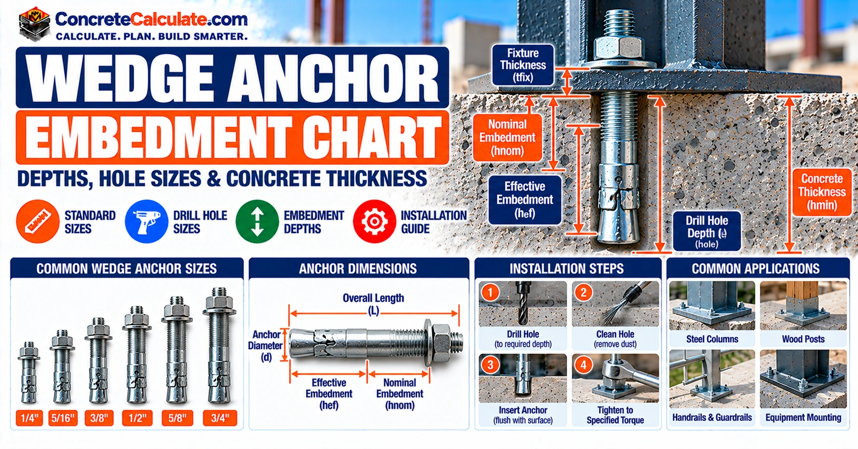
Wedge Anchor Embedment ChartDepth, Hole Size and Concrete Thickness
A product-specific reference for contractors, engineers, installers and inspectors: effective and nominal embedment, minimum hole depth, concrete thickness, anchor length and fixture thickness, with verified Hilti and Simpson examples.
Jump to the Chart Reviewed by Muhammad Ramzan Babar, PhD Researcher (Plasma Physics) & Calculator Developer, View Profile
Key Facts
- A wedge anchor diameter does not set one embedment. Each product lists several evaluated depths, each with its own hole depth and minimum concrete thickness.
- Nominal embedment, effective embedment, hole depth, concrete thickness and anchor length are five different dimensions.
- Example: Hilti KB-TZ2 1/2 in. at 2-1/2 in. effective embedment has 3 in. nominal embedment, a 3-1/4 in. hole and a 5 in. minimum thickness.
Wedge Anchor Embedment Chart: Quick Reference
Verified effective embedment, nominal embedment, hole depth and concrete thickness for one named product family.
A wedge anchor’s diameter does not set one correct embedment depth. Each product has specific evaluated embedments, and each embedment has its own hole depth and minimum concrete thickness. This chart lists one manufacturer’s verified combinations. General sizes and drill bits are in the Wedge Anchor Size Chart; this page goes deeper on embedment.
How to Read This Chart
Pick the diameter, then pick one evaluated row. Take hnom as the installed depth, h0 as the minimum drilled depth, and h as the minimum concrete thickness. Example: a 1/2 in. KB-TZ2 with 2-1/2 in. effective embedment has a 3 in. nominal embedment, a 3-1/4 in. minimum hole depth and a 5 in. minimum concrete thickness. That is one evaluated combination for that product, not a recommendation for every 1/2 in. wedge anchor.
| Anchor diameter | Effective embedment hef | Nominal embedment hnom | Minimum hole depth h0 | Minimum concrete thickness h |
|---|---|---|---|---|
| 1/4 in. | 1-1/2 in. | 1-3/4 in. | 2 in. | 3-1/4 in. |
| 3/8 in. | 1-1/2 in. | 1-7/8 in. | 2 in. | 3-1/4 in. |
| 3/8 in. | 2 in. | 2-1/2 in. | 2-3/4 in. | 4 in. |
| 3/8 in. | 2-1/2 in. | 3 in. | 3-1/4 in. | 5 in. |
| 1/2 in. | 1-1/2 in. | 2 in. | 2-1/4 in. | 3-1/2 in. |
| 1/2 in. | 2 in. | 2-1/2 in. | 2-3/4 in. | 4 in. |
| 1/2 in. | 2-1/2 in. | 3 in. | 3-1/4 in. | 5 in. |
| 1/2 in. | 3-1/4 in. | 3-3/4 in. | 4-1/4 in. | 5-1/2 in. |
| 5/8 in. | 2-3/4 in. | 3-1/4 in. | 3-3/4 in. | 5 in. |
| 5/8 in. | 3-1/4 in. | 3-3/4 in. | 4-1/4 in. | 5-1/2 in. |
| 5/8 in. | 4 in. | 4-1/2 in. | 4-3/4 in. | 6 in. |
| 3/4 in. | 3-1/4 in. | 4 in. | 4-1/4 in. | 5-1/2 in. |
| 3/4 in. | 3-3/4 in. | 4-1/2 in. | 4-3/4 in. | 6 in. |
| 3/4 in. | 4-3/4 in. | 5-1/2 in. | 5-3/4 in. | 8 in. |
- The 1/2 in. anchor at 1-1/2 in. effective embedment applies only to the carbon-steel KB-TZ2.
- Values apply only to the Hilti KB-TZ2. Do not apply them to Simpson Strong-Bolt 2, DEWALT Power-Stud, other wedge anchors or sleeve anchors.
- Check the selected anchor’s material, manufactured length, concrete condition, edge distance, spacing and permitted drilling method.
- Minimum member thickness is not the required hole depth. No row alone establishes structural capacity.
- Compare every row with the current product data and evaluation report before relying on it.
Source: Hilti KWIK BOLT TZ2 (KB-TZ2) carbon steel. Data editions: ICC-ES ESR-4266 (reissued December 2023, revised October 2024), Table 1, and Hilti North American Product Technical Guide, Volume 2, Edition 22, Table 1. Units are inches.
What Is Wedge Anchor Embedment?
Definition
Embedment is how far an anchor goes into the concrete. The word covers several different depths, so a chart must say which one it means: nominal embedment, effective embedment, drilled-hole depth or concrete thickness.
Expansion Mechanism
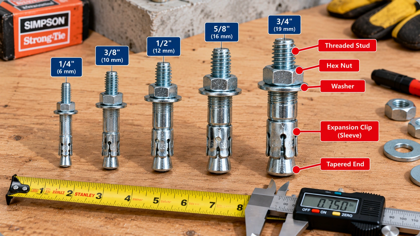
A wedge anchor is a torque-controlled expansion anchor. It has a threaded shaft, an expansion clip and a tapered end. As the nut is tightened, the shaft is pulled up into the clip, which expands against the wall of the drilled hole and locks the anchor in the concrete.
Why Embedment Matters
The expansion zone sits at the bottom of the anchor, so its depth below the surface decides how much concrete the anchor engages. The installed depth is also not the same as the anchor’s overall length, which must additionally cover the fixture, washer, nut and thread projection.
Wedge Anchor Embedment Standards and Codes
Three layers decide how a wedge anchor is installed and designed, and no single source replaces the other two.
| Document | Role | Typical content |
|---|---|---|
| ACI 318 Chapter 17 | Structural design of anchors to concrete | Steel, breakout, pullout, pryout, edge distance, spacing, thickness, seismic |
| ACI 355.2 | Qualification of post-installed mechanical anchors | Test requirements, including cracked-concrete performance |
| ICC-ES evaluation report | Product-specific recognition | Approved embedments, hole depths, thicknesses and limits |
| Manufacturer installation instructions | How to install the exact product | Bit, hole depth, cleaning, torque, setting |
ACI 318 Chapter 17
ACI 318 Chapter 17 sets the strength design of anchors in concrete. Embedment affects several concrete failure modes, but not every one, and the governing edition depends on the locally adopted code.
ACI 355.2
ACI 355.2 sets the tests that qualify post-installed mechanical anchors. The ICC-ES criteria for mechanical anchors (AC193) are built on it. Qualification is not the same as structural design.
ICC-ES and Manufacturer Requirements
Evaluation reports list the permitted configurations. ESR-4266 covers the Hilti KB-TZ2 and ESR-3037 covers the Simpson Strong-Bolt 2. The manufacturer’s instructions then control the installation.
Adopted Code Controls
The locally adopted building code edition, the project specifications and the current evaluation report for the exact product control the job.
Nominal vs. Effective Embedment Depth
Nominal Embedment
Nominal embedment hnom is the installed depth the manufacturer specifies, and it is the depth the installer measures and drives to. Hilti notes that the nominal embedment is tied to the effective embedment: for a given diameter, specific nominal embedments produce specific effective embedments.
Effective Embedment
Effective embedment hef is the depth used in structural calculations, where the expansion elements bear against the concrete. After the anchor is torqued, the visible nominal depth can change slightly, but the effective embedment, which sets the capacity, does not if the anchor was installed correctly.
Manufacturer Examples
| Anchor diameter | Nominal embedment hnom | Effective embedment hef | Difference |
|---|---|---|---|
| 3/8 in. | 1-7/8 in. | 1-1/2 in. | 3/8 in. |
| 3/8 in. | 2-1/2 in. | 2 in. | 1/2 in. |
| 1/2 in. | 3 in. | 2-1/2 in. | 1/2 in. |
| 5/8 in. | 4-1/2 in. | 4 in. | 1/2 in. |
| 3/4 in. | 5-1/2 in. | 4-3/4 in. | 3/4 in. |
Source: Hilti KWIK BOLT TZ2 (KB-TZ2) carbon steel. Data editions: ICC-ES ESR-4266 (reissued December 2023, revised October 2024), Table 1, and Hilti North American Product Technical Guide, Volume 2, Edition 22, Table 1.
Difference Between Nominal and Effective Embedment
Variables: hnom = nominal embedment; hef = effective embedment
Practical interpretation: Do not generalize this difference to other anchors or other configurations of the same anchor.
No Universal Conversion
hef is not a fixed percentage of hnom, and it is not always hnom minus a fixed amount. Take both values from the product’s tables.
Minimum Drilled-Hole Depth
The hole must be deeper than the anchor’s nominal embedment. Drilling only to the effective embedment depth will not let the anchor seat.
Hole Depth vs. Embedment
Hole depth h0 is measured from the specified concrete surface and has to hold the anchor to its nominal embedment plus the space below the anchor tip.
Extra Depth
| Anchor configuration | Nominal embedment hnom | Minimum hole depth h0 | Published difference |
|---|---|---|---|
| 1/4 in., hef = 1.5 in. | 1-3/4 in. | 2 in. | 1/4 in. |
| 3/8 in., hef = 2 in. | 2-1/2 in. | 2-3/4 in. | 1/4 in. |
| 1/2 in., hef = 3.25 in. | 3-3/4 in. | 4-1/4 in. | 1/2 in. |
| 5/8 in., hef = 4 in. | 4-1/2 in. | 4-3/4 in. | 1/4 in. |
| 3/4 in., hef = 4.75 in. | 5-1/2 in. | 5-3/4 in. | 1/4 in. |
Additional Drilled-Hole Depth
Variables: h0 = minimum hole depth; hnom = nominal embedment
Practical interpretation: This compares published dimensions. It is not a rule for choosing drill depth.
Source: Hilti KWIK BOLT TZ2 (KB-TZ2) carbon steel. Data editions: ICC-ES ESR-4266 (reissued December 2023, revised October 2024), Table 1, and Hilti North American Product Technical Guide, Volume 2, Edition 22, Table 1.
For comparison, the Simpson Strong-Bolt 2 table below shows a different pattern.
| Configuration | Minimum hole depth | h0 – hnom (derived) |
|---|---|---|
| 3/8 in., hnom 1-7/8 in. | 2 in. | 1/8 in. |
| 1/2 in., hnom 2-3/4 in. | 3 in. | 1/4 in. |
| 5/8 in., hnom 3-3/8 in. | 3-5/8 in. | 1/4 in. |
| 3/4 in., hnom 4-1/8 in. | 4-3/8 in. | 1/4 in. |
Source: Simpson Strong-Tie Strong-Bolt 2, zinc-plated carbon steel, ICC-ES ESR-3037. Data edition: Simpson Strong-Tie catalog C-A-2023, Strong-Bolt 2 design information (concrete).
Verification
The extra depth is not a drilling allowance you choose. Use the manufacturer’s minimum hole depth, and set the drill stop to it. Drill-bit diameters are in the Concrete Anchor Drill Bit Size Chart.
Wedge Anchor Embedment by Diameter
Each common diameter has several evaluated depths. These short notes use the Hilti KB-TZ2 table above.
1/4- and 3/8-Inch Anchors
The 1/4 in. anchor has a single configuration at 1-1/2 in. effective embedment. The 3/8 in. anchor has three: 1-1/2 in., 2 in. and 2-1/2 in., with minimum thicknesses of 3-1/4 in., 4 in. and 5 in.
1/2-Inch Anchors
The 1/2 in. anchor has four configurations from 1-1/2 in. to 3-1/4 in. effective embedment. At 2 in. it needs a 4 in. member and a 2-3/4 in. hole. At 3-1/4 in. it needs a 5-1/2 in. member and a 4-1/4 in. hole.
5/8-, 3/4-, and 1-Inch Anchors
The larger sizes start deeper. The 5/8 in. anchor begins at 2-3/4 in. effective embedment, the 3/4 in. anchor at 3-1/4 in., and the 1 in. anchor at 4 in.
| Anchor diameter | hef | hnom | h0 | Minimum concrete thickness h |
|---|---|---|---|---|
| 1 in. | 4 in. | 4-5/8 in. | 5 in. | 8 in. |
| 1 in. | 5-3/4 in. | 6-3/8 in. | 6-3/4 in. | 10 in. |
Source: Hilti KWIK BOLT TZ2 (KB-TZ2) carbon steel. Data editions: ICC-ES ESR-4266 (reissued December 2023, revised October 2024), Table 1, and Hilti North American Product Technical Guide, Volume 2, Edition 22, Table 1.
| Anchor diameter da | Effective embedment hef | R |
|---|---|---|
| 1/4 in. | 1-1/2 in. | 6.00 |
| 3/8 in. | 1-1/2 in. | 4.00 |
| 3/8 in. | 2 in. | 5.33 |
| 3/8 in. | 2-1/2 in. | 6.67 |
| 1/2 in. | 1-1/2 in. | 3.00 |
| 1/2 in. | 2 in. | 4.00 |
| 1/2 in. | 2-1/2 in. | 5.00 |
| 1/2 in. | 3-1/4 in. | 6.50 |
| 5/8 in. | 2-3/4 in. | 4.40 |
| 5/8 in. | 3-1/4 in. | 5.20 |
| 5/8 in. | 4 in. | 6.40 |
| 3/4 in. | 3-1/4 in. | 4.33 |
| 3/4 in. | 3-3/4 in. | 5.00 |
| 3/4 in. | 4-3/4 in. | 6.33 |
Embedment-to-Diameter Ratio
Variables: hef = effective embedment; da = nominal diameter
Practical interpretation: The ratio is descriptive. It is not a minimum embedment rule.
Hilti KB-TZ2 Embedment Chart
The main chart above comes from the Hilti KB-TZ2 setting and thickness tables. This section explains its scope.
Evaluated Configurations
| Anchor diameter | Number of listed configurations |
|---|---|
| 1/4 in. | 1 |
| 3/8 in. | 3 |
| 1/2 in. | 4 |
| 5/8 in. | 3 |
| 3/4 in. | 3 |
| 1 in. | 2 |
Effective and Nominal Depths
Each listed effective depth has one matching nominal depth. You choose the configuration, then use that row’s hole depth and member thickness. Do not mix values from different rows.
Hole and Concrete Thickness
The hef = 1-1/2 in. configuration for the 1/2 in. anchor applies only to carbon steel. Stainless-steel KB-TZ2 anchors have their own listed configurations, so confirm the evaluation before applying this table to them.
Source: Hilti KWIK BOLT TZ2 (KB-TZ2) carbon steel. Data editions: ICC-ES ESR-4266 (reissued December 2023, revised October 2024), Table 1, and Hilti North American Product Technical Guide, Volume 2, Edition 22, Table 1.
Simpson Strong-Bolt 2 Embedment Chart
Nominal Embedment
Simpson lists two or three nominal embedments for each diameter. The shallowest depth for the 1/2 in., 5/8 in. and 3/4 in. sizes is based on internal testing and is not listed in the evaluation report, so it is left out below.
| Anchor diameter | Nominal embedment hnom | Effective embedment hef | Minimum hole depth | Minimum overall anchor length |
|---|---|---|---|---|
| 3/8 in. | 1-7/8 in. | 1-1/2 in. | 2 in. | 2-3/4 in. |
| 3/8 in. | 2-7/8 in. | 2-1/2 in. | 3 in. | 3-1/2 in. |
| 1/2 in. | 2-3/4 in. | 2-1/4 in. | 3 in. | 3-3/4 in. |
| 1/2 in. | 3-7/8 in. | 3-3/8 in. | 4-1/8 in. | 5-1/2 in. |
| 5/8 in. | 3-3/8 in. | 2-3/4 in. | 3-5/8 in. | 4-1/2 in. |
| 5/8 in. | 5-1/8 in. | 4-1/2 in. | 5-3/8 in. | 6 in. |
| 3/4 in. | 4-1/8 in. | 3-3/8 in. | 4-3/8 in. | 5-1/2 in. |
| 3/4 in. | 5-3/4 in. | 5 in. | 6 in. | 7 in. |
Source: Simpson Strong-Tie Strong-Bolt 2, zinc-plated carbon steel, ICC-ES ESR-3037. Data edition: Simpson Strong-Tie catalog C-A-2023, Strong-Bolt 2 design information (concrete). 1/4 in. anchors are not shown. Simpson notes that its 1/4 in. by 1-3/4 in. anchor is below the minimum embedment in the code report.
Effective Embedment
The difference between hnom and hef is 3/8 in. for the 3/8 in. anchor, 1/2 in. for the 1/2 in. anchor, 5/8 in. for the 5/8 in. anchor and 3/4 in. for the 3/4 in. anchor. That equals the diameter for this product, but it is a product feature, not a rule for wedge anchors in general.
Product Differences
| Diameter | Hilti KB-TZ2 hef options | Simpson Strong-Bolt 2 hef options (ESR-3037) |
|---|---|---|
| 3/8 in. | 1-1/2, 2, 2-1/2 in. | 1-1/2, 2-1/2 in. |
| 1/2 in. | 1-1/2, 2, 2-1/2, 3-1/4 in. | 2-1/4, 3-3/8 in. |
| 5/8 in. | 2-3/4, 3-1/4, 4 in. | 2-3/4, 4-1/2 in. |
| 3/4 in. | 3-1/4, 3-3/4, 4-3/4 in. | 3-3/8, 5 in. |
Never combine Simpson and Hilti rows without naming the product.
Minimum Wedge Anchor Embedment
Product-Specific Minimums
The smallest listed embedment depends on the product. A 1/2 in. KB-TZ2 can be used at 1-1/2 in. effective embedment, but a 1/2 in. Strong-Bolt 2 begins at 2-1/4 in.
| Diameter | Hilti KB-TZ2 | Simpson Strong-Bolt 2 (ESR-3037) |
|---|---|---|
| 3/8 in. | 1-1/2 in. (hnom 1-7/8 in.) | 1-1/2 in. (hnom 1-7/8 in.) |
| 1/2 in. | 1-1/2 in. (hnom 2 in., carbon steel only) | 2-1/4 in. (hnom 2-3/4 in.) |
| 5/8 in. | 2-3/4 in. (hnom 3-1/4 in.) | 2-3/4 in. (hnom 3-3/8 in.) |
| 3/4 in. | 3-1/4 in. (hnom 4 in.) | 3-3/8 in. (hnom 4-1/8 in.) |
Selection Criteria
The smallest published embedment is a lower bound for qualification and may not give enough design resistance for the intended load. Choose the embedment from the design, then check that the product lists it.
Structural Requirements
Diameter-only rules such as 4d, 6d or 8d fail because products differ, as the ratio table showed. ASTM F1554 specifies anchor-rod materials and properties, not a universal embedment schedule for every concrete anchor. See the Anchor Bolt Size Chart for general anchor types.
Wedge Anchor Length vs. Embedment
Overall Length
Overall length L is the full manufactured length, measured from the tip to the top of the threaded end. It is not the hole depth and not the embedment.
| Dimension | What it represents | Source |
|---|---|---|
| Nominal embedment hnom | Installed depth required | Product evaluation |
| Fixture thickness tfix | Attached steel, wood or other approved fixture | Actual project measurement |
| Nut and washer allowance | Hardware dimensions | Product specification |
| Thread projection | Required exposed thread | Manufacturer instructions |
| Overall anchor length L | Manufactured anchor length | Product catalog |
| Maximum fixture thickness | Permitted fixture for the chosen length | Manufacturer catalog |
Installed Depth
Only the nominal embedment is below the concrete surface. The rest of the anchor goes through the fixture and carries the washer and nut.
Thread Projection
Published minimum lengths show how much extra length is needed above the installed depth. For the Strong-Bolt 2, it ranges from 5/8 in. to 1-5/8 in.
| Diameter | hnom | Minimum overall length | Minimum length – hnom |
|---|---|---|---|
| 3/8 in. | 1-7/8 in. | 2-3/4 in. | 7/8 in. |
| 3/8 in. | 2-7/8 in. | 3-1/2 in. | 5/8 in. |
| 1/2 in. | 2-3/4 in. | 3-3/4 in. | 1 in. |
| 1/2 in. | 3-7/8 in. | 5-1/2 in. | 1-5/8 in. |
| 5/8 in. | 3-3/8 in. | 4-1/2 in. | 1-1/8 in. |
| 5/8 in. | 5-1/8 in. | 6 in. | 7/8 in. |
| 3/4 in. | 4-1/8 in. | 5-1/2 in. | 1-3/8 in. |
| 3/4 in. | 5-3/4 in. | 7 in. | 1-1/4 in. |
Source: Simpson Strong-Tie Strong-Bolt 2, zinc-plated carbon steel, ICC-ES ESR-3037. Data edition: Simpson Strong-Tie catalog C-A-2023, Strong-Bolt 2 design information (concrete). Last column calculated.
General product sizing is in the Wedge Anchor Size Chart.
How to Calculate Wedge Anchor Length
Fixture Thickness
Measure the fixture as installed, including any shim or grout pad that sits under the nut and washer.
Required Embedment
Take hnom from the selected configuration. It is the depth the anchor must reach, not the anchor’s length.
Hardware Allowance
The nut, washer and exposed thread need length above the fixture. The size of that allowance depends on the product and diameter.
Preliminary Length Formula
Preliminary Overall Anchor Length (hypothetical allowance)
Variables: hnom = nominal embedment; tfix = fixture thickness; a = allowance for nut, washer, exposed thread and other geometry
Practical interpretation: The 3/4 in. allowance is hypothetical, not a verified Hilti or Simpson dimension. Select a real catalog length using the product’s maximum fixture thickness and installation tables, and do not assume a 4-1/4 in. anchor exists. The published allowances in the previous section range from 5/8 in. to 1-5/8 in.
Product Catalog Verification
The manufacturer’s maximum fixture thickness for each catalog length governs actual selection. The estimate only shows the order of magnitude.
Wedge Anchor Fixture Thickness Chart
A fixture thickness chart has to come from a manufacturer’s catalog, because the maximum fixture for each length is a rated value.
Steel Fixtures
Thin brackets leave more thread for the nut. Thick base plates use up thread length, so choose a longer catalog length and check it against the rating. Plate thickness is covered in the Steel Plate Thickness Chart.
Wood Fixtures
Wood can compress under the washer and nut. Follow the manufacturer’s guidance for wood fixtures.
Manufacturer Limits
| Size × length (in.) | Model number | Thread length |
|---|---|---|
| 3/8 × 3 | STB2-37300 | 1-9/16 in. |
| 3/8 × 3-1/2 | STB2-37312 | 2-1/16 in. |
| 3/8 × 5 | STB2-37500 | 3-9/16 in. |
| 1/2 × 4-1/4 | STB2-50414 | 2-9/16 in. |
| 1/2 × 5-1/2 | STB2-50512 | 3-13/16 in. |
| 1/2 × 7 | STB2-50700 | 5-5/16 in. |
| 5/8 × 5 | STB2-62500 | 2-15/16 in. |
| 5/8 × 6 | STB2-62600 | 3-15/16 in. |
| 5/8 × 7 | STB2-62700 | 4-15/16 in. |
Source: Simpson Strong-Tie Strong-Bolt 2, zinc-plated carbon steel, ICC-ES ESR-3037. Data edition: Simpson Strong-Tie catalog C-A-2023, Strong-Bolt 2 design information (concrete). Catalog lengths and thread lengths as published.
Do Not Infer Fixture Limits
Do not infer a maximum fixture thickness from a nominal diameter or from the thread length alone. Use the manufacturer’s catalog rating for the exact model.
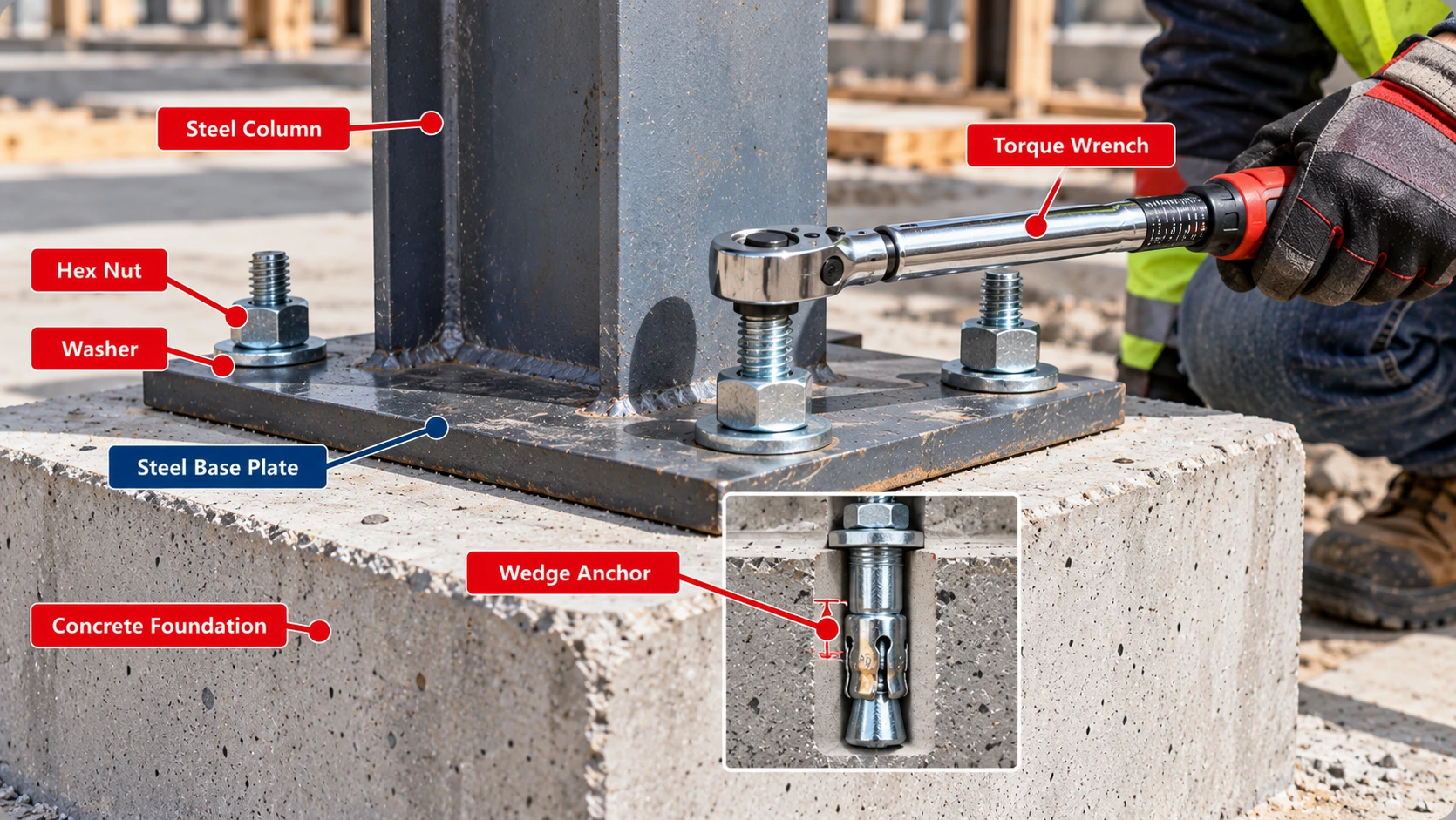
Minimum Concrete Thickness for Wedge Anchors
Minimum member thickness is a separate requirement from hole depth, and it comes from the product evaluation.
| Diameter | Effective embedment | Minimum concrete thickness |
|---|---|---|
| 1/4 in. | 1-1/2 in. | 3-1/4 in. |
| 3/8 in. | 2 in. | 4 in. |
| 1/2 in. | 2-1/2 in. | 5 in. |
| 5/8 in. | 4 in. | 6 in. |
| 3/4 in. | 4-3/4 in. | 8 in. |
Source: Hilti KWIK BOLT TZ2 (KB-TZ2) carbon steel. Data editions: ICC-ES ESR-4266 (reissued December 2023, revised October 2024), Table 1, and Hilti North American Product Technical Guide, Volume 2, Edition 22, Table 1.
Slabs
A 4 in. slab fits only some configurations, as the next sections show. Simpson states that its Strong-Bolt 2 is qualified for a minimum concrete thickness of 3-1/4 in.
Walls
Wall thickness is checked the same way. Remember the concrete behind the hole in a wall may hold reinforcement.
Footings and Pedestals
Pedestals and footings also have edges, so check thickness and edge distance together. A 4 in. slab cannot be assumed suitable for every anchor configuration.
Wedge Anchor Embedment in 4-Inch Concrete
A 4 in. slab is a common site condition. It works only for configurations whose published minimum is 4 in. or less.
Evaluated Configurations
| Diameter | hef | Minimum thickness h | Hole depth h0 | Concrete left below hole in a 4 in. slab (derived) |
|---|---|---|---|---|
| 1/4 in. | 1-1/2 in. | 3-1/4 in. | 2 in. | 2 in. |
| 3/8 in. | 1-1/2 in. | 3-1/4 in. | 2 in. | 2 in. |
| 3/8 in. | 2 in. | 4 in. | 2-3/4 in. | 1-1/4 in. |
| 1/2 in. | 1-1/2 in. | 3-1/2 in. | 2-1/4 in. | 1-3/4 in. |
| 1/2 in. | 2 in. | 4 in. | 2-3/4 in. | 1-1/4 in. |
Source: Hilti KWIK BOLT TZ2 (KB-TZ2) carbon steel. Data editions: ICC-ES ESR-4266 (reissued December 2023, revised October 2024), Table 1, and Hilti North American Product Technical Guide, Volume 2, Edition 22, Table 1.
Installation Limits
The hole must reach its minimum depth without breaking through the slab. In a 4 in. slab, the 3/8 in. anchor at 2 in. embedment leaves 1-1/4 in. below the hole.
Structural Checks
A 4 in. slab that meets the product minimum can still fail other checks. Edge distance, spacing and the design loads decide whether the anchor is acceptable. Do not give a blanket approval to wedge anchors in 4 in. concrete.
Wedge Anchor Embedment in 6-Inch Concrete
Embedment Options
All KB-TZ2 configurations except the deepest 3/4 in. and the 1 in. anchors fit a 6 in. slab by thickness.
| Diameter | hef | hnom | Hole depth h0 | Concrete left below hole (derived) |
|---|---|---|---|---|
| 1/4 in. | 1-1/2 in. | 1-3/4 in. | 2 in. | 4 in. |
| 3/8 in. | 1-1/2 in. | 1-7/8 in. | 2 in. | 4 in. |
| 3/8 in. | 2 in. | 2-1/2 in. | 2-3/4 in. | 3-1/4 in. |
| 3/8 in. | 2-1/2 in. | 3 in. | 3-1/4 in. | 2-3/4 in. |
| 1/2 in. | 1-1/2 in. | 2 in. | 2-1/4 in. | 3-3/4 in. |
| 1/2 in. | 2 in. | 2-1/2 in. | 2-3/4 in. | 3-1/4 in. |
| 1/2 in. | 2-1/2 in. | 3 in. | 3-1/4 in. | 2-3/4 in. |
| 1/2 in. | 3-1/4 in. | 3-3/4 in. | 4-1/4 in. | 1-3/4 in. |
| 5/8 in. | 2-3/4 in. | 3-1/4 in. | 3-3/4 in. | 2-1/4 in. |
| 5/8 in. | 3-1/4 in. | 3-3/4 in. | 4-1/4 in. | 1-3/4 in. |
| 5/8 in. | 4 in. | 4-1/2 in. | 4-3/4 in. | 1-1/4 in. |
| 3/4 in. | 3-1/4 in. | 4 in. | 4-1/4 in. | 1-3/4 in. |
| 3/4 in. | 3-3/4 in. | 4-1/2 in. | 4-3/4 in. | 1-1/4 in. |
Source: Hilti KWIK BOLT TZ2 (KB-TZ2) carbon steel. Data editions: ICC-ES ESR-4266 (reissued December 2023, revised October 2024), Table 1, and Hilti North American Product Technical Guide, Volume 2, Edition 22, Table 1.
Hole Depth
The deeper options leave less concrete below the hole. The 5/8 in. anchor at 4 in. effective embedment leaves only 1-1/4 in.
Concrete Thickness Remaining Below the Hole
Variables: r = geometric concrete remaining below the hole; hc = member thickness; h0 = hole depth
Practical interpretation: This does not establish structural adequacy, safe clearance to reinforcement, or the product’s minimum thickness.
Member Thickness
A hole shallower than the slab is not automatically acceptable. Check the product minimum, the loads, edge distance and spacing, and look for reinforcement before drilling.
Wedge Anchor Embedment and Load Capacity
Embedment strongly affects one failure mode, concrete breakout. It does not control the others in the same way, and the lowest strength governs.
Concrete Breakout
ACI 318 calculates breakout strength from a basic value that contains hef raised to the 1.5 power for the standard single-anchor case.
Simplified Tension Breakout Relationship
Variables: Nb = basic concrete breakout strength of a single anchor in tension; hef = effective embedment
Practical interpretation: This is not an 84% increase in allowable load. Actual equations add factors, the governing mode may be steel, pullout or shear, the deeper embedment must be evaluated for the product, and thickness, edge and spacing must still be met.
Pullout
Pullout depends on the expansion mechanism, the evaluated depth and concrete strength. Product tables supply the values.
Steel Strength
Steel strength does not rise with embedment. Once the breakout strength exceeds it, a deeper anchor gains nothing.
| Failure mechanism | Why embedment matters | Additional checks |
|---|---|---|
| Concrete breakout in tension | Effective embedment sets breakout geometry and resistance | Edge distance, spacing, group action |
| Pullout | Expansion mechanism and evaluated depth affect resistance | Product data, concrete strength |
| Steel tension failure | May govern regardless of added embedment | Anchor steel strength |
| Concrete breakout in shear | Geometry and edge location affect resistance | Load direction, edge distance |
| Pryout | Anchorage geometry and breakout resistance matter | ACI shear design |
| Splitting | Expansion forces interact with concrete geometry | Thickness, edge distance, spacing |
That is why deeper is not always better.
Wedge Anchor Embedment Under Tension
Tension Loading
Tension design checks steel strength (ACI 318-19 Section 17.6.1), concrete breakout (17.6.2) and pullout (17.6.3), and the lowest governs.
Effective Embedment
hef enters the breakout and pullout checks. Products supply effectiveness factors for cracked and uncracked concrete. For the Simpson Strong-Bolt 2, the kuncr values are 24 or 27 and the kcr value is 17, depending on size and embedment.
Concrete Breakout
The breakout strength also depends on concrete strength and on edge and spacing modification factors, so embedment alone gives no capacity table.
Pullout Resistance
Pullout values come from product testing. The Simpson catalog gives pullout strength at 2,500 psi concrete and says to scale it by the square root of the strength ratio for stronger concrete. See the Concrete PSI Chart for strength classes.
Wedge Anchor Embedment Under Shear
Shear Loading
Shear checks steel strength (ACI 318-19 Section 17.7.1), concrete breakout toward an edge (17.7.2) and pryout (17.7.3).
Edge Breakout
Shear breakout depends mainly on edge distance and on the load-bearing length of the anchor, which is limited to the smaller of hef and 8 times the diameter.
Pryout
Shallow anchors can pry out a cone of concrete behind the anchor. ACI uses a coefficient of 1.0 for shallower embedment and 2.0 for deeper embedment, with the break at an effective embedment of 2-1/2 in., and the Simpson tables follow that pattern.
Load Direction
Shear toward an edge, away from an edge and parallel to an edge differ. Shear resistance cannot be set from embedment alone.
Cracked vs. Uncracked Concrete
Product Qualification
The KB-TZ2 is evaluated for cracked and uncracked concrete. The Simpson Strong-Bolt 2 is listed for cracked and uncracked concrete in the 3/8 in. through 1 in. sizes, while its 1/4 in. size is outside the cracked-concrete scope of the catalog table.
Concrete Condition
The assumption changes available resistance. A shallow embedment does not have the same approvals as a deeper one.
Embedment Options
The Simpson catalog notes that for some embedment depths, cracked-concrete installation is beyond the scope of its table, and that certain depths are based on internal testing and are not listed in the evaluation report.
Seismic Considerations
Seismic design needs anchors qualified for seismic loading. Both products here list Seismic Design Categories A through F for their evaluated configurations. Concrete strength also matters; see the Concrete Strength Gain Chart before anchoring into young concrete.
Wedge Anchor Spacing and Embedment
Center-to-Center Spacing
Spacing is measured from anchor centerline to centerline.
Anchor Groups
Closer anchors share breakout regions, so group strength is less than the sum of single anchors.
Concrete Breakout Interaction
In the simplified model, breakout regions of two anchors meet at 3 times the effective embedment.
Minimum Installation Spacing
The KB-TZ2 3/8 in. anchor at 2 in. embedment needs 6 in. spacing at a 2-1/2 in. edge distance, or 2-1/4 in. spacing at a 3-1/2 in. edge distance. The full treatment is in the Concrete Anchor Spacing Chart.
Wedge Anchor Edge Distance and Embedment
Measuring Concrete Edge Distance
Measure from the anchor centerline to the nearest free concrete edge, not to the edge of the fixture.
Expansion-Induced Splitting
Expansion pressure can split concrete near an edge or a close neighbor, which is why products publish minimum edge distance.
Edge Breakout
Anchors near an edge can break out toward it, especially in shear.
Corners and Narrow Members
In a corner two edges apply at once. Embedment cannot be chosen independently of edge distance, and the product tables couple the two.
Wedge Anchor Installation Torque
Torque-Controlled Expansion
Tightening the nut to the specified torque pulls the anchor into its clip and sets the expansion. Too little torque may leave the anchor unset, and too much can damage the anchor or the concrete.
Product Torque
| Diameter | Hilti KB-TZ2 torque (ft-lb) | Simpson Strong-Bolt 2 torque (ft-lb) | KB-TZ2 fixture hole | Strong-Bolt 2 fixture hole |
|---|---|---|---|---|
| 1/4 in. | 4 | 4 | 5/16 in. | 5/16 in. |
| 3/8 in. | 30 | 30 | 7/16 in. | 7/16 in. |
| 1/2 in. | 50 | 60 | 9/16 in. | 9/16 in. |
| 5/8 in. | 40 | 90 | 11/16 in. | 11/16 in. |
| 3/4 in. | 110 | 150 | 13/16 in. | 7/8 in. |
| 1 in. | 185 | 230 | 1-1/8 in. | 1-1/8 in. |
Sources: Hilti KWIK BOLT TZ2 (KB-TZ2) carbon steel. Data editions: ICC-ES ESR-4266 (reissued December 2023, revised October 2024), Table 1, and Hilti North American Product Technical Guide, Volume 2, Edition 22, Table 1. Simpson Strong-Tie Strong-Bolt 2, zinc-plated carbon steel, ICC-ES ESR-3037. Data edition: Simpson Strong-Tie catalog C-A-2023, Strong-Bolt 2 design information (concrete).
The 1/2 in. anchor needs 50 ft-lb for the KB-TZ2 but 60 ft-lb for the Strong-Bolt 2. A general bolt torque chart is not a substitute, because anchor torque is a product setting, not a clamp-load estimate.
Installation Errors
Do not use an impact wrench to set or tighten the Strong-Bolt 2, as Simpson instructs. Use a calibrated torque wrench and follow the product’s instructions for the specific diameter and material.
Drill Bit Size and Hole Preparation
Bit Selection
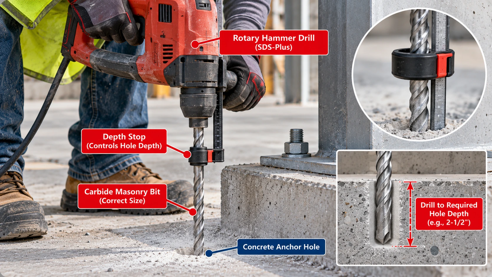
Use a carbide-tipped masonry bit of the same diameter as the anchor. Simpson specifies this for the Strong-Bolt 2, and Hilti’s instructions call for bits meeting ANSI B212.15 for the KB-TZ2. Oversized holes make setting difficult and reduce capacity. Bit sizes are in the Concrete Anchor Drill Bit Size Chart.
Hole Depth
Drill to at least the minimum hole depth. ANSI B212.15 controls bit dimensions and tolerances, not embedment or capacity.
Cleaning and Drilling Method
Simpson’s instructions call for blowing the hole clean with compressed air (overhead holes need not be blown clean), or drilling deep enough to hold the embedment plus the dust. Permitted drilling methods differ by product, so follow the exact instructions.
How to Install Wedge Anchors at the Correct Depth
Layout and Drilling
- Confirm the product, diameter, embedment and design on the approved plans.
- Mark hole locations and check edges, spacing and reinforcement.
- Drill to the specified minimum hole depth with the correct carbide bit.
- Prepare the hole as the manufacturer instructs.
Look for reinforcement, conduit and post-tensioning before you drill. The Concrete Cover Chart shows typical cover but does not show where it is safe to drill.
Setting
- Assemble the anchor with the nut flush with the top and set it through the fixture.
- Drive the anchor to its nominal embedment.
Torque and Inspection
- Tighten to the specified installation torque with a torque wrench.
- Inspect the installed anchor against the plans and instructions.
This sequence is general. The selected product’s installation instructions control every step, including bit type, hole cleaning and torque.
Wedge Anchor Embedment for Steel Base Plates
Fixture Thickness
The base plate’s thickness sets how much anchor length is used above the concrete. Plate thickness is in the Steel Plate Thickness Chart. Hole diameters in the plate must also suit the anchor; see the torque and fixture-hole table above.
Embedment
Choose the embedment from the design, then pick a catalog length long enough for the plate, washer, nut and thread. The anchor, plate, concrete and loads form one connection.
Structural Design
A multi-anchor base plate also has group effects, edge distances and eccentricity. The approved design controls the anchor count, layout and embedment.
Wedge Anchor Embedment for Equipment and Brackets
Equipment Bases
Equipment anchors need the actual loads and the equipment maker’s pattern. Do not recommend a diameter or embedment without them.
Structural Brackets
Bracket anchors carry shear and tension together, so embedment is one input among many.
Dynamic Loads
Vibration, impact and seismic loads call for approved design. Some anchors are not rated for fatigue or shock, and the evaluation report states the limits.
Wedge Anchors vs. Sleeve Anchors vs. Drop-In Anchors
The three families grip concrete differently, so their embedment tables cannot be swapped.
| Anchor | How it expands | Where the embedment comes from |
|---|---|---|
| Wedge anchor | Torque-controlled; clip expands as the nut is tightened | Nominal and effective embedment from the evaluation report |
| Sleeve anchor | Torque-controlled; a sleeve expands along its length | Embedment from the sleeve anchor’s own data |
| Drop-in anchor | Displacement-controlled; set by driving an internal plug with a setting tool | Setting depth from the drop-in anchor’s own data |
Expansion Mechanisms
Wedge anchors expand at the tip, sleeve anchors along a sleeve, and drop-in anchors by displacement of a plug.
Embedment Differences
See the Sleeve Anchor Size Chart and the Drop-In Anchor Size Chart for their own depths.
Installation Requirements
Each family has its own setting method and torque or setting-tool requirement.
Common Wedge Anchor Embedment Mistakes
Depth Errors
Treating effective embedment as nominal embedment
They are different dimensions.
Drilling only to the effective depth
The hole must reach the minimum hole depth.
Assuming hole depth equals anchor length
The anchor is longer than the hole depth.
Using universal 4d, 6d or 8d rules
Products differ, as the ratio table shows.
Selecting embedment from diameter alone
Pick an evaluated configuration.
Assuming deeper embedment guarantees more load
Steel or pullout may govern.
Product Selection Errors
Using an anchor too short for the fixture
Length must cover the fixture, nut and thread.
Ignoring the maximum fixture thickness
Use the manufacturer’s rating.
Using a table for the wrong material finish
Carbon and stainless have different listings.
Using another manufacturer’s data
Name the product.
Using uncracked data in cracked concrete
Check the qualification.
Using outdated evaluation data
Confirm the current report.
Structural and Installation Errors
Ignoring minimum concrete thickness
The member must meet the product minimum.
Drilling through a thin slab
Check thickness against hole depth.
Ignoring reinforcement or post-tensioning
Locate it before drilling.
Using the wrong drill-bit diameter
Match the anchor and bit.
Skipping hole preparation
Follow the instructions.
Applying incorrect torque
Use the product torque.
Installing too close to an edge
Check edge distance.
Ignoring anchor-group effects
Close anchors share breakout.
Wedge Anchor Embedment Inspection Checklist
Geometry
Verify diameter, length, embedment, hole depth, thickness, edge distance and spacing against the plans before and after installation.
| Inspection item | Required verification |
|---|---|
| Anchor manufacturer | Exact approved brand |
| Product model | Exact evaluated anchor family |
| Diameter | Matches design |
| Overall length | Correct manufactured length |
| Fixture thickness | Within product limit |
| Nominal embedment | Meets specified configuration |
| Effective embedment | Matches design data |
| Drilled-hole depth | Meets installation instructions |
| Concrete thickness | Meets evaluated minimum |
| Concrete strength | Meets design requirements |
| Concrete condition | Cracked or uncracked as specified |
| Edge distance | Meets installation and design limits |
| Anchor spacing | Meets installation and design limits |
| Drill bit | Correct diameter and type |
| Hole preparation | Manufacturer compliant |
| Installation torque | Correct and verified |
| Corrosion protection | Suitable for exposure |
| Evaluation report | Current and applicable |
| Structural approval | Matches approved plans |
Installation
Confirm the bit, hole preparation and torque match the instructions.
Documentation
Keep the approved plans and the current evaluation report on site.
Wedge Anchor Embedment Limitations and Safety
Chart Scope
The main chart is one manufacturer’s published example. The Simpson tables are a second, separate product. Neither is a universal embedment schedule.
Product-Specific Requirements
The chart does not establish allowable tension load, allowable shear load, cracked-concrete approval, seismic qualification, adequate edge distance or spacing, concrete thickness for every application, safe fixture thickness or proper installation torque.
The Evaluation Report, Instructions and Design Control
The current evaluation report, the manufacturer’s instructions and the approved structural design control. Compare each value here with the current product data before relying on it.
Structural Design Requirements
Anchorage design follows ACI 318 Chapter 17 for the edition your building code adopts. The KB-TZ2 values come from product data. The earlier Hilti guide that some sources cite contains nuclear-facility load tables, which are not general building design capacities.
Installation and Inspection
Follow the instructions for the exact product, material and configuration.
Primary References
Wedge Anchor Embedment FAQs
Minimum Embedment
How deep should a wedge anchor be embedded?
It depends on the product and the design. For the Hilti KB-TZ2 3/8 in. anchor, the evaluated nominal embedments are 1-7/8, 2-1/2 and 3 in., with effective embedments of 1-1/2, 2 and 2-1/2 in.
What is the minimum embedment for a 1/4-inch wedge anchor?
For the Hilti KB-TZ2, the listed configuration is 1-1/2 in. effective and 1-3/4 in. nominal, with a 2 in. minimum hole depth and 3-1/4 in. minimum concrete thickness. Confirm any other product’s listing.
What is the minimum embedment for a 3/8-inch wedge anchor?
The KB-TZ2 starts at 1-1/2 in. effective embedment (1-7/8 in. nominal). The Simpson Strong-Bolt 2 also starts at 1-1/2 in. effective embedment, with 1-7/8 in. nominal embedment.
How deep should a 1/2-inch wedge anchor go?
The KB-TZ2 lists 2, 2-1/2, 3 and 3-3/4 in. nominal embedment (1-1/2 in. effective applies to carbon steel only). The Strong-Bolt 2 lists 2-3/4 and 3-7/8 in. nominal in its code report. Choose the one the design calls for.
What is the minimum embedment for a 5/8-inch wedge anchor?
For the KB-TZ2, 2-3/4 in. effective and 3-1/4 in. nominal. For the Strong-Bolt 2, 2-3/4 in. effective and 3-3/8 in. nominal.
How deep should a 3/4-inch wedge anchor be embedded?
The KB-TZ2 lists 4, 4-1/2 and 5-1/2 in. nominal. The Strong-Bolt 2 lists 4-1/8 and 5-3/4 in. nominal. The design decides which.
Is there a universal wedge anchor embedment chart?
No. Each product lists its own evaluated embedments, so a chart is valid only for the product named.
What is the difference between nominal and effective embedment?
Nominal embedment is the installed depth the manufacturer specifies. Effective embedment is the depth used in structural design calculations. They differ by an amount that depends on the product and configuration.
Is drilled-hole depth the same as embedment?
No. The hole must be deeper than the nominal embedment to hold the anchor tip and dust. The minimum hole depth comes from the manufacturer.
How much deeper should the hole be than the anchor embedment?
Use the manufacturer’s minimum hole depth. In the KB-TZ2 table the hole is 1/8 in. to 1/2 in. deeper than the nominal embedment, and the Simpson Strong-Bolt 2 uses 1/8 in. or 1/4 in. for the sizes shown.
Can wedge anchors be installed in 4-inch concrete?
Only configurations whose published minimum thickness is 4 in. or less. For the KB-TZ2 that includes the 3/8 in. at 2 in. embedment and the 1/2 in. at 2 in. embedment, subject to edge distance, spacing and design checks.
Can wedge anchors be installed in a 6-inch slab?
Many KB-TZ2 configurations have a minimum thickness of 6 in. or less, but a 6 in. slab is not a blanket approval. Check the hole depth, remaining concrete, reinforcement, edge distance and design loads.
Does deeper embedment increase anchor strength?
It can raise concrete breakout resistance, but steel strength, pullout or shear may govern instead. Deeper does not automatically mean a higher allowable load.
How do I calculate wedge anchor length?
Add the nominal embedment, the fixture thickness and an allowance for the nut, washer and thread, then check the result against the manufacturer’s catalog lengths and maximum fixture thickness.
Does fixture thickness affect anchor selection?
Yes. A thicker fixture uses more of the anchor’s length above the concrete, so a longer anchor is needed, within the manufacturer’s maximum fixture thickness.
Can I use a longer wedge anchor for greater embedment?
A longer anchor does not change embedment by itself. It reaches a deeper embedment only if you drill and install it to a listed deeper configuration and the concrete thickness and design allow it.
Can a wedge anchor be embedded too deeply?
Yes, if the hole passes through a thin member or goes beyond the product’s evaluated range. Use only listed embedments and keep the member thickness above the product minimum.
What happens if a wedge anchor is not embedded deeply enough?
The expansion zone may be too shallow to meet its evaluated capacity or may not set correctly, and the installation may not comply with the evaluation report.
Does concrete strength affect the required embedment?
The tabulated embedments do not change with strength, but design resistance does, and products state a permitted strength range. Simpson’s pullout values, for example, are given at 2,500 psi.
Do cracked-concrete anchors require different embedment?
The product must be qualified for cracked concrete at the chosen embedment. Some embedment depths are outside the cracked-concrete scope in Simpson’s table, so check each configuration.
What code governs wedge anchor embedment?
ACI 318 Chapter 17 governs anchor design where your building code adopts it. The evaluation report and the manufacturer’s instructions govern the product and its installation.
Can I use a wedge anchor’s size chart instead of its evaluation report?
No. A size chart helps identify the product, but embedment, hole depth, thickness and limits come from the current evaluation report and instructions.
Download Wedge Anchor Embedment Chart PDF
Use your browser’s print function to save this page as a PDF for jobsite binders and submittal files. The printed version hides interactive elements and keeps the tables.