Counterbore Size Chart – Socket Head Cap Screw Recess Dimensions
Counterbore Size Chart
Socket Head Cap Screw Recess Dimensions
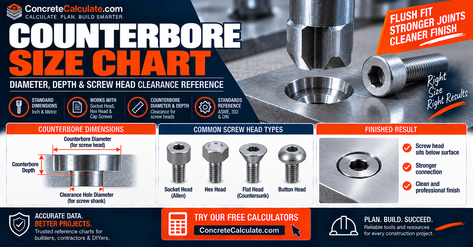
Counterbore diameter, depth, clearance-hole size, and recess dimensions for inch and metric socket-head cap screws, plus counterbore versus countersink versus spotface, washer/tool clearance, fillet clearance, and current ASME B18.3, ISO 4762, and DIN 974 standards.
 Reviewed by Muhammad Ramzan Babar, PhD Researcher (Plasma Physics) & Calculator Developer, View Profile
Counterbore dimensions depend on fastener head geometry, not nominal thread diameter alone
A counterbore must clear the fastener head in diameter and provide enough depth for the head to sit flush or recessed. Unlike a countersink, a counterbore is cylindrical with a flat bottom. Do not size a counterbore from nominal thread diameter alone, and do not make counterbore diameter exactly equal to screw-head diameter without required assembly clearance.
Counterbore Size Chart, Quick Reference
Two flagship tables, with inch and metric fastener systems kept separate.
Inch Socket-Head Cap Screw Counterbore Chart
| Screw Size | Close Hole | Normal Hole | Max Head Diameter | Head Height | Counterbore Diameter | Flush Counterbore Depth |
|---|---|---|---|---|---|---|
| #4 | 0.120 | 0.136 | 0.183 | 0.112 | 7/32 (0.219) | ~0.112 + tolerance |
| #6 | 0.150 | 0.166 | 0.226 | 0.138 | 9/32 (0.281) | ~0.138 + tolerance |
| #8 | 0.180 | 0.196 | 0.270 | 0.164 | 5/16 (0.312) | ~0.164 + tolerance |
| #10 | 0.206 | 0.221 | 0.312 | 0.190 | 3/8 (0.375) | ~0.190 + tolerance |
| 1/4 in. | 0.266 | 0.281 | 0.375 | 0.250 | 7/16 (0.438) | ~0.250 + tolerance |
| 5/16 in. | 0.328 | 0.344 | 0.469 | 0.312 | 17/32 (0.531) | ~0.312 + tolerance |
| 3/8 in. | 0.391 | 0.406 | 0.562 | 0.375 | 5/8 (0.625) | ~0.375 + tolerance |
| 1/2 in. | 0.516 | 0.531 | 0.750 | 0.500 | 13/16 (0.812) | ~0.500 + tolerance |
Counterbore diameters shown are common ASME B18.3-style drill/counterbore values. Flush depth is based on head height and must account for the controlling drawing and manufacturing tolerance.
Metric Socket-Head Cap Screw Counterbore Chart
| Screw | Close Hole | Normal Hole | Head Diameter | Head Height | Counterbore Diameter | Flush Depth |
|---|---|---|---|---|---|---|
| M4 | 4.4 mm | 4.8 mm | 7 mm | 4 mm | 8.25 mm | 4 mm + tolerance |
| M5 | 5.4 mm | 5.8 mm | 8.5 mm | 5 mm | 10.0 mm | 5 mm + tolerance |
| M6 | 6.4 mm | 6.8 mm | 10 mm | 6 mm | 11.2 mm | 6 mm + tolerance |
| M8 | 8.4 mm | 8.8 mm | 13 mm | 8 mm | 14.5 mm | 8 mm + tolerance |
| M10 | 10.5 mm | 10.8 mm | 16 mm | 10 mm | 17.5 mm | 10 mm + tolerance |
| M12 | 12.5 mm | 13.0 mm | 18 mm | 12 mm | 19.5 mm | 12 mm + tolerance |
ISO 4762 defines metric socket-head cap screw head dimensions; DIN 974-1 defines associated metric counterbore manufacturing dimensions. Exact clearance and depth must still follow the controlling drawing.
Important scope note
Counterbore dimensions depend on fastener head geometry. Do not size a counterbore from nominal thread diameter alone.
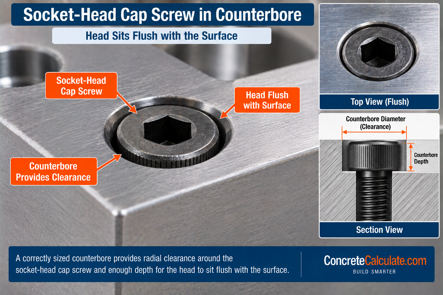
What Is a Counterbore?
A cylindrical, flat-bottomed recess around a smaller hole.
A counterbore is machined concentrically around a smaller hole so a fastener head, nut, or washer can sit flush with or below the surface. Typical uses include socket-head cap screws, machine assemblies, tooling, fixtures, recessed bolt heads, and recessed nuts or washers.
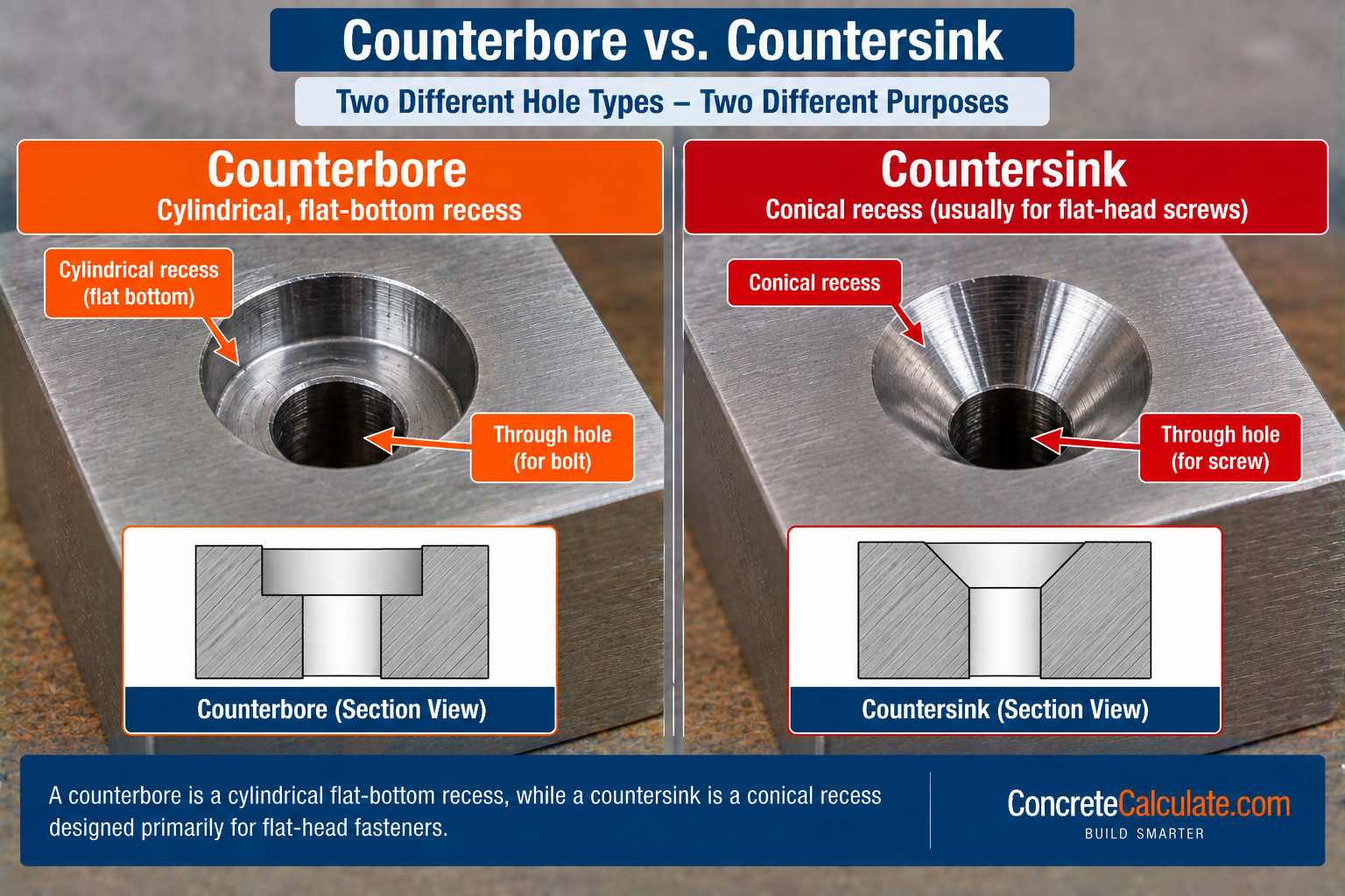
Counterbore vs Countersink
This distinction must appear early.
| Feature | Counterbore | Countersink |
|---|---|---|
| Shape | Cylindrical | Conical |
| Bottom | Flat | Angled |
| Typical fastener | Socket-head cap screw | Flat-head screw |
| Main dimensions | Diameter + depth | Diameter + angle + depth |
| Tool | Counterbore/end mill | Countersink cutter |
For conical-recess dimensions and 82°/90°/100° fastener head matching, see the Countersink Size Chart.
Counterbore vs Spotface
Every counterbore creates a flat seat, but not every spotface recesses a fastener head.
A counterbore is deep enough to recess a fastener head. A spotface is usually a shallow machined bearing surface intended to flatten a rough or cast surface and provide even bearing for a bolt head, nut, or washer.
Counterbore Dimension Anatomy
The fundamental technical visual.
Counterbore Diameter vs Screw Head Diameter
Key relationship: counterbore diameter must be larger than screw head diameter.
Dcb must be greater than Dhead to accommodate head manufacturing tolerance, assembly, tool access, coatings where applicable, and positional variation. Do not use Dcb = Dhead as a general manufacturing rule; the applicable standard or drawing should control.
Counterbore Depth vs Screw Head Height
Head-height tolerance and required seating condition both matter.
| Seating Condition | Depth Relationship |
|---|---|
| Flush | Hcb approximately equals Khead |
| Recessed | Hcb greater than Khead |
| Proud | Hcb less than Khead |
For nominal flush installation, counterbore depth approximately equals head height, but actual production depth may include intentional allowance. Head-height tolerance and drawing requirements must be considered before setting a production depth.
Flush Counterbore Depth Chart
Depth basis is head height plus the specified seating tolerance, not an arbitrary universal allowance.
| Fastener Size | Max Head Height | Recommended Flush Depth Basis | Optional Recess Allowance |
|---|---|---|---|
| 1/4 in. SHCS | 0.250 in. | Head height plus drawing tolerance | Only when specified |
| 3/8 in. SHCS | 0.375 in. | Head height plus drawing tolerance | Only when specified |
| M6 SHCS | 6 mm | Head height plus drawing tolerance | Only when specified |
| M10 SHCS | 10 mm | Head height plus drawing tolerance | Only when specified |
Do not add arbitrary universal extra depth such as +0.010 in. or +0.5 mm unless explicitly identified as a shop practice rather than a standard requirement.
Inch Socket-Head Cap Screw Counterbore Chart
One of the primary tables, tied to ASME B18.3-style geometry.
| Screw | Head Dia. Max | Head Height Max | Close Hole | Normal Hole | Counterbore Dia. | Depth |
|---|---|---|---|---|---|---|
| #4 | 0.183 | 0.112 | 0.120 | 0.136 | 0.219 | 0.112 + tol. |
| #8 | 0.270 | 0.164 | 0.180 | 0.196 | 0.312 | 0.164 + tol. |
| #10 | 0.312 | 0.190 | 0.206 | 0.221 | 0.375 | 0.190 + tol. |
| 1/4 in. | 0.375 | 0.250 | 0.266 | 0.281 | 0.438 | 0.250 + tol. |
| 3/8 in. | 0.562 | 0.375 | 0.391 | 0.406 | 0.625 | 0.375 + tol. |
| 1/2 in. | 0.750 | 0.500 | 0.516 | 0.531 | 0.812 | 0.500 + tol. |
ASME B18.3-2026 is the current inch authority and includes drill/counterbore tables in supporting appendices. Values shown follow established ASME B18.3-style drill/counterbore practice; confirm final dimensions with the current standard and drawing.
Metric Socket-Head Cap Screw Counterbore Chart
Equivalent metric table tied to ISO 4762 and DIN 974-1.
| Screw | Head Dia. | Head Height | Clearance Hole | Counterbore Dia. | Counterbore Depth |
|---|---|---|---|---|---|
| M4 | 7 mm | 4 mm | 4.8 mm normal | 8.25 mm | 4 mm + tol. |
| M5 | 8.5 mm | 5 mm | 5.8 mm normal | 10.0 mm | 5 mm + tol. |
| M6 | 10 mm | 6 mm | 6.8 mm normal | 11.2 mm | 6 mm + tol. |
| M8 | 13 mm | 8 mm | 8.8 mm normal | 14.5 mm | 8 mm + tol. |
| M10 | 16 mm | 10 mm | 10.8 mm normal | 17.5 mm | 10 mm + tol. |
| M12 | 18 mm | 12 mm | 13.0 mm normal | 19.5 mm | 12 mm + tol. |
ISO 4762 defines head geometry. DIN 974-1 supplies current counterbore manufacturing dimensions for cylindrical-head screws. Clearance-hole classes should follow the applicable assembly standard and drawing.
ASME B18.3-2026 Counterbore Dimensions
Main U.S. standards section.
ASME B18.3-2026 covers socket-head cap screws, shoulder screws, set screws, driving keys, and explicitly includes appendices with drill sizes, counterbore sizes, and dimensional formulas. Use B18.3-2026, not B18.3-2012, as the current edition; older online charts often still cite the older edition.
ISO 4762 Metric Socket-Head Screw Dimensions
Defines the metric screw geometry that drives counterbore design.
ISO 4762:2004 remains current after confirmation in 2023. It covers hexagon socket-head cap screws with coarse threads from M1.6 through M64, product grade A. Relevant dimensions include nominal thread diameter, head diameter, head height, and socket dimensions.
DIN 974-1 Metric Counterbore Dimensions
Important technical differentiator.
DIN 974-1:2008-02 remains current and specifically covers counterbore manufacturing dimensions for hexagon socket-head cap screws and cheese/pan-head screws. DIN 974-1 provides recess dimensions, while ISO 4762 defines the fastener itself. Keep those standards roles separate.
Counterbore Diameter vs Clearance Hole Diameter
A counterbored hole has two distinct diameters.
| Dimension | Function |
|---|---|
| d = clearance hole | Lower through-hole allowing threaded shank to pass |
| D = counterbore | Upper cylindrical recess clearing the fastener head |
D is greater than d. Use the Clearance Hole Size Chart to select the smaller lower hole.
Close vs Normal Clearance Under a Counterbore
The counterbore can remain the same while the smaller through-hole changes.
ASME-based counterbore references distinguish close and normal clearance holes beneath the same counterbore. The counterbore is controlled by the head, while the lower hole changes according to the required assembly fit.
Counterbore vs Tap Drill and Pilot Hole
Two common configurations and a key warning.
| Assembly | Lower Hole |
|---|---|
| Through bolt/screw | Counterbore + clearance hole |
| Screw threaded into same part | Counterbore + tapped hole |
The smaller lower hole can therefore be a clearance hole or a tap-drilled/threaded hole. Do not confuse counterbore diameter with either clearance-hole or tap-drill diameter. See the Tap Drill Chart and Pilot Hole Size Chart.
Socket-Head Cap Screw Counterbores
The page’s main fastener application.
Socket-head cap screws are commonly counterbored because their cylindrical head has a relatively high profile, and recessed installation provides machinery clearance and a clean surface. Use ASME B18.3 for inch-series screws and ISO 4762 for metric screws.
Button-Head and Low-Head Screw Counterbores
Do not reuse socket-head cap screw recess dimensions for other head forms.
Button-head screws have wider, much lower, rounded heads, while low-head socket screws have reduced head height. Both can require different counterbore diameters, depths, and loadability checks than a standard SHCS. Tie exact dimensions to the relevant product standard or manufacturer data.
Cheese-Head and Pan-Head Counterbores
A useful specialist section for metric readers.
DIN 974-1 specifically covers counterbore manufacturing dimensions for socket-head cap screws, cheese-head screws, and pan-head screws. These head shapes differ substantially from SHCS geometry, so socket-head counterbore dimensions should not be reused without verification.
Counterbores for Hex Bolts and Nuts
Separate from cylindrical socket heads.
DIN 974-2 covers counterbores associated with hexagon bolts and nuts in components with clearance holes. Consider wrench/socket access, head or nut across-flats dimension, across-corners envelope, and washer diameter. Do not size these recesses from socket-head tables.
Counterbores for Washer Clearance
A recess may need to clear a screw head only, or an entire washer/nut assembly.
If a washer is inside the recess, counterbore diameter must be greater than washer outside diameter with appropriate clearance. Head clearance does not automatically guarantee washer clearance. See the Washer Size Chart for washer OD data.
Counterbore Diameter for Socket and Tool Access
A common design mistake is clearing the head but blocking the installation tool.
For hex bolts and nuts, consider socket outside diameter, wrench access, and extension geometry. Head clearance does not automatically guarantee tool clearance. See the Socket Size Chart and Hex Bolt Size Chart.
Counterbore Edge Distance and Wall Thickness
A large counterbore near an edge can leave very little material.
Check distance from recess edge to component edge, neighboring holes, walls or bosses, and the surrounding load path. Avoid a universal minimum unless tied to a specific engineering design standard.
Counterbore Depth and Remaining Material Thickness
Deep recesses reduce remaining section thickness.
For plate thickness T, remaining material thickness equals T minus Hcb. This matters for strength, thread engagement, bending, cracking, and breakthrough. Do not counterbore deeper than the part can support merely to hide the head.
Flush vs Recessed vs Proud Fastener Heads
Counterbore depth directly determines seating condition.
| Condition | Definition |
|---|---|
| Proud | Head projects above surface |
| Flush | Top of head aligns with surface |
| Recessed | Head sits below surface |
Counterbore Bottom Geometry and Corner Radius
Real counterbores do not always have mathematically perfect sharp internal corners.
A real counterbore can have tool corner radius, a small bottom radius, or an entrance chamfer. Check head under-radius or fillet clearance, particularly where sharp hole edges could interfere with a socket-head screw fillet in harder materials.
Fastener Head Fillet Clearance
A strong engineering detail beyond generic charts.
The underside of a socket-head cap screw can have a fillet near the head-to-shank transition. If the lower hole or counterbore corner interferes, the head may not seat flat, the fillet can be damaged, and fatigue performance can suffer. Provide the required edge relief or countersinking where the controlling screw standard or drawing requires it.
Counterboring Thin vs Thick Material
Material thickness changes what recess depth is safe.
Thin Material
If counterbore depth approaches plate thickness, too little material can remain. Consider a lower-profile screw, countersunk screw, external head, thicker boss, or redesign.
Thick Plate and Machine Parts
Thicker components generally provide more recess depth, but rigidity, concentricity, depth control, chip evacuation, and flat bottom geometry must still be checked.
Counterbore Tools and Machining Methods
Common tool choices.
Potential tools include piloted counterbores, end mills, flat-bottom drills, CNC interpolation, and dedicated counterbore cutters. Do not prescribe cutting speed or feed without material, tool, and machine context.
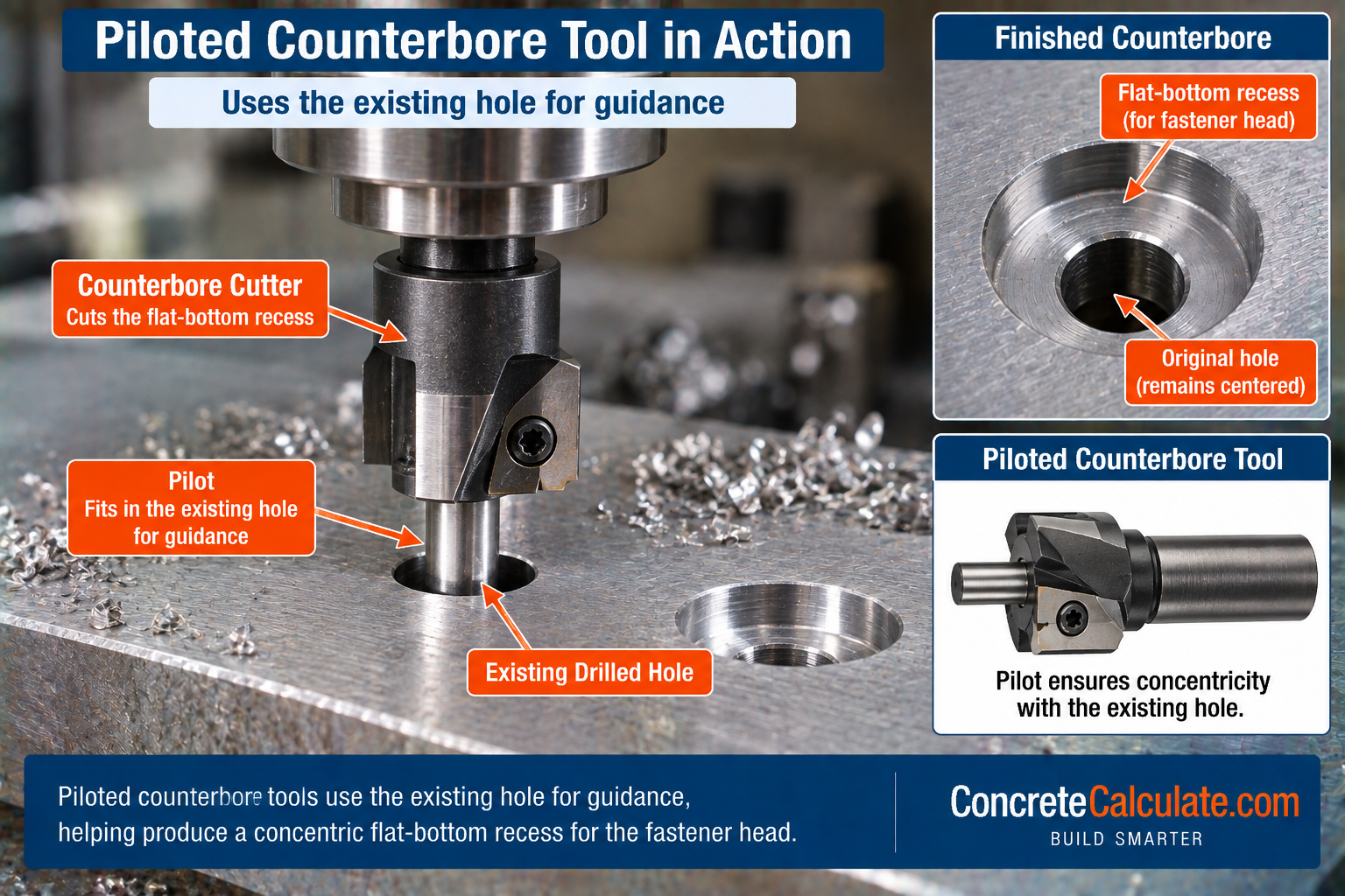
Piloted vs Non-Piloted Counterbores
Alignment, rigidity, and repeatability differ by method.
| Method | How Alignment Is Controlled |
|---|---|
| Piloted Counterbore | Pilot follows the predrilled hole and helps concentricity |
| Non-Piloted / CNC Method | Position controlled by machine or toolpath |
Choose based on the required alignment, rigidity, machine control, and repeatability. ISO and DIN tool standards may be relevant for individual tools, but tooling should not dominate this fastener-reference page.
How to Measure and Choose a Counterbore
Practical identification and selection workflows.
Measure an Existing Counterbore
Choose the Correct Counterbore
Common Mistakes and Chart Limitations
Confusing counterbore with countersink
Counterbore is cylindrical; countersink is conical.
Sizing recess from nominal thread diameter only
Counterbore must be based on actual head geometry.
Making counterbore diameter equal to head diameter
Assembly and manufacturing clearance are required.
Making depth exactly nominal head height without tolerance
Flush/recessed condition and head-height tolerance must be considered.
Applying ISO/DIN metric dimensions to ASME inch screws
Inch and metric product standards are separate.
Reusing SHCS recesses for button or low-head screws
These heads have different dimensions and loadability.
Forgetting clearance-hole size beneath recess
Counterbore diameter and through-hole diameter are separate dimensions.
Ignoring washer OD or socket access
Head clearance alone may not clear the washer or tool.
Leaving an internal corner that prevents seating
Head fillet clearance and bottom relief can be required.
Counterboring too deep in thin material
Deep recesses remove section thickness and can cause breakthrough or weakness.
Using outdated ASME B18.3 editions
ASME B18.3-2026 is the current edition.
Read before finalizing a counterbore detail
Counterbore size depends on fastener head geometry, and thread diameter alone is insufficient. Counterbore diameter and clearance-hole diameter are separate, and depth depends on head height plus required seating condition. Inch and metric standards differ, and socket-head, button-head, low-head, pan-head, and hex-head products require different recesses. Washers can require larger recesses, tool access may require additional clearance, head fillets need relief, and material thickness can limit allowable depth. Standardized dimensions do not mean every size is commercially stocked. Final dimensions should follow the controlling fastener/product standard and engineering drawing.
Counterbore Size FAQs
Download the Counterbore Size Chart
Get a printable reference including inch/metric SHCS counterbore tables, diameter/depth guidance, and machining-detail checklists for shop or fabrication use.
![Rebar Size Chart - Complete #3 to No. 20 [64] Diameter, Area & Grade Reference](https://concretecalculate.com/wp-content/uploads/2026/07/Rebar-Size-Chart-2026-Complete-3-to-No.-20-64-Diameter-Area-Grade-Reference-390x220.png)