Flange Bolt Size Chart 2026 – ASME B16.5 Bolt and Stud Sizes
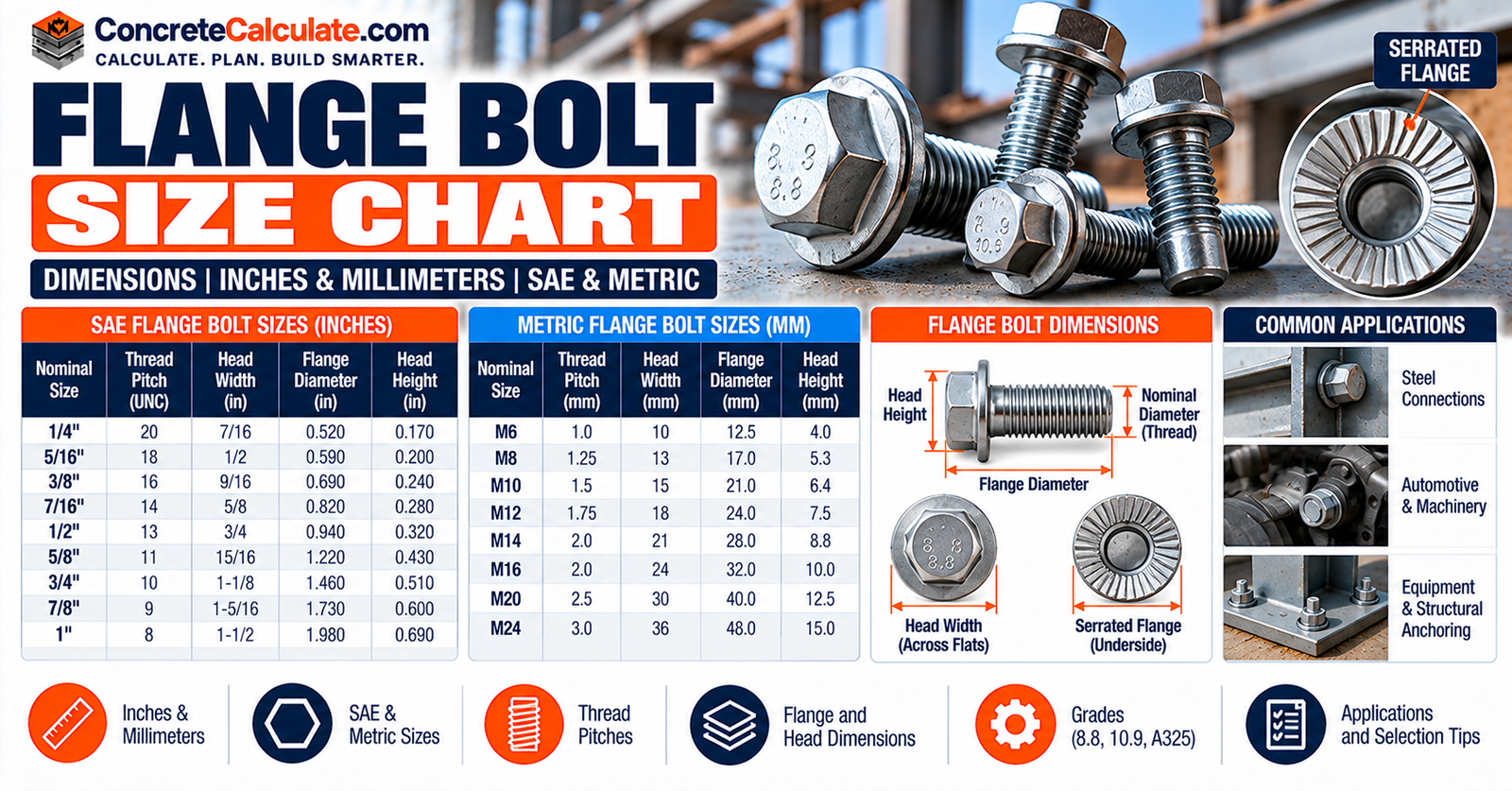
Flange Bolt Size Chart
ASME B16.5 Bolt and Stud Sizes
Find the number, diameter and reference length of studs for Class 150 to 2500 flanges, and learn why bolt diameter is not hole diameter, how stud length is built up, and why torque is never read from flange class alone.
 Reviewed by Muhammad Ramzan Babar, PhD Researcher (Plasma Physics) & Calculator Developer – View Profile
Short Answer
Flange bolting depends on both NPS and pressure class. A Class 150 NPS 4 flange uses eight 5/8 in. studs (3-1/2 in. reference length for a 1/16 in. raised face) in 0.75 in. holes, while Class 300 NPS 4 uses eight 3/4 in. studs. Stud length comes from the joint stack-up, and torque is determined for the joint following ASME PCC-1, never read from the class.
Flange Bolt Size Chart
Look up bolt count, nominal diameter and reference stud length by NPS and pressure class. The Class 150 chart comes first because it answers the most common question.
How to Read the Chart
Find the NPS in the left column. The next columns give the number of bolts or studs, the nominal diameter and the reference stud length for a 1/16 in. raised-face joint. Always identify both NPS and flange class before selecting flange bolting. Stud lengths are reference assembly lengths and are not universal for every flange type, gasket, washer arrangement, facing or project specification.
Class 150 Quick Reference
| NPS | No. of Bolts / Studs | Bolt / Stud Diameter | Decimal (in.) | 1/16 in. RF Stud Length | RTJ Stud Length |
|---|---|---|---|---|---|
| 1/2″ | 4 | 1/2″ | 0.50 | 2-1/4″ | Not listed |
| 3/4″ | 4 | 1/2″ | 0.50 | 2-1/2″ | Not listed |
| 1″ | 4 | 1/2″ | 0.50 | 2-1/2″ | 3″ |
| 1-1/4″ | 4 | 1/2″ | 0.50 | 2-3/4″ | 3-1/4″ |
| 1-1/2″ | 4 | 1/2″ | 0.50 | 2-3/4″ | 3-1/4″ |
| 2″ | 4 | 5/8″ | 0.63 | 3-1/4″ | 3-3/4″ |
| 2-1/2″ | 4 | 5/8″ | 0.63 | 3-1/2″ | 4″ |
| 3″ | 4 | 5/8″ | 0.63 | 3-1/2″ | 4″ |
| 4″ | 8 | 5/8″ | 0.63 | 3-1/2″ | 4″ |
| 6″ | 8 | 3/4″ | 0.75 | 4″ | 4-1/2″ |
| 8″ | 8 | 3/4″ | 0.75 | 4-1/4″ | 4-3/4″ |
| 10″ | 12 | 7/8″ | 0.88 | 4-1/2″ | 5″ |
| 12″ | 12 | 7/8″ | 0.88 | 4-3/4″ | 5-1/4″ |
Bolt and bolt-hole diameter are different quantities. For the flange OD, thickness, bolt circle and hole diameter tables, see the Pipe Flange Size Chart. The complete NPS 1/2 to 24 table is in the Class 150 section below.
Reference: ASME B16.5, manufacturer-reproduced bolting table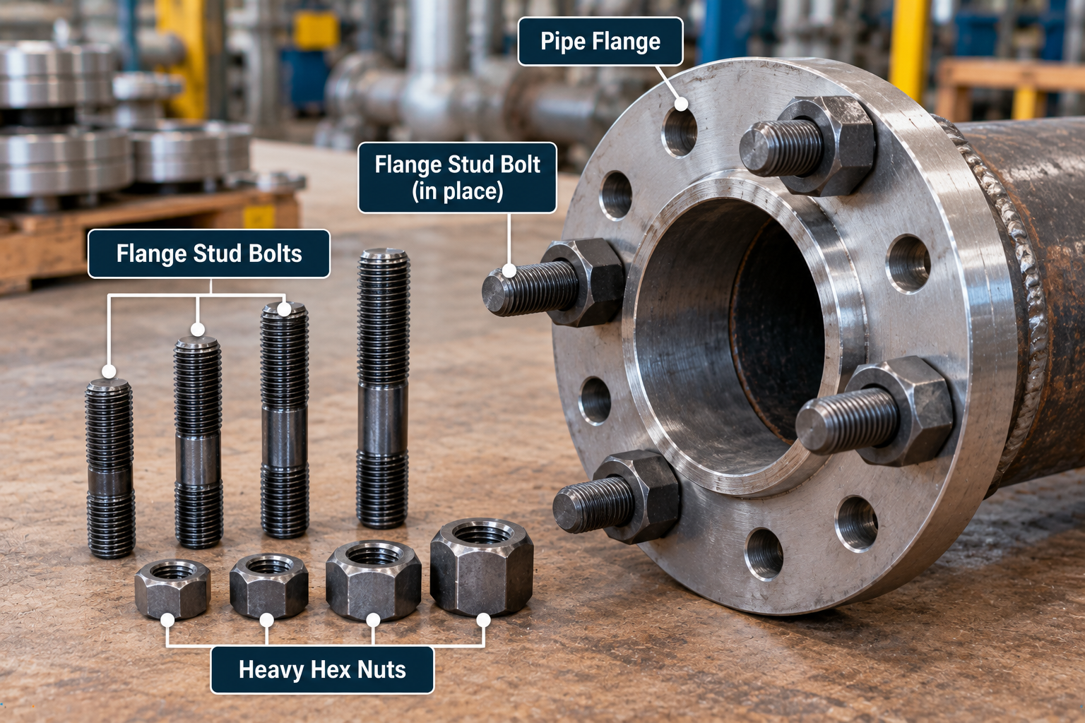
How to Read Flange Bolt Sizes
Bolt/Stud Diameter
The nominal threaded-fastener diameter.
Bolt Count
The total number of bolts or studs around the flange.
Stud Length
The end-to-end length according to the product and joint convention.
Bolt Hole and Bolt Circle
The bolt hole is the clearance hole through the flange, and the bolt circle is the circle through the hole centers. These are different quantities from the bolt diameter.
| Term | Meaning |
|---|---|
| Bolt / stud diameter | Nominal threaded-fastener diameter |
| Bolt count | Number of fasteners around the flange |
| Stud length | End-to-end length per the product and joint convention |
| Bolt-hole diameter | Clearance hole through the flange |
| Bolt-circle diameter | Circle through the flange hole centers |
ASME B16.5 Flange Bolting Scope
ASME B16.5-2025 covers pipe flanges and flanged fittings NPS 1/2 through 24 and includes requirements and recommendations on flange bolting, gaskets and joints. Do not extend B16.5 bolting tables above NPS 24.
| Class | B16.5 Coverage |
|---|---|
| 150 | NPS 1/2 to 24 |
| 300 | NPS 1/2 to 24 |
| 400 | NPS 1/2 to 24 |
| 600 | NPS 1/2 to 24 |
| 900 | NPS 1/2 to 24 |
| 1500 | NPS 1/2 to 24 |
| 2500 | NPS 1/2 to 12 |
The reference table used here lists Class 150, 300, 600, 900, 1500 and 2500. Class 400 is also covered by B16.5, but it is not tabulated in that source, so it is not published here.
Class 150 Flange Bolt Size Chart
Class 150 uses 1/2 in. studs up to NPS 1-1/2, then 5/8, 3/4, 7/8, 1, 1-1/8 and 1-1/4 in. as NPS increases to 24. Stud lengths are for 1/16 in. raised-face joints, and RTJ lengths are listed where applicable.
| NPS | No. of Bolts / Studs | Bolt / Stud Diameter | Decimal (in.) | 1/16 in. RF Stud Length | RTJ Stud Length |
|---|---|---|---|---|---|
| 1/2″ | 4 | 1/2″ | 0.50 | 2-1/4″ | Not listed |
| 3/4″ | 4 | 1/2″ | 0.50 | 2-1/2″ | Not listed |
| 1″ | 4 | 1/2″ | 0.50 | 2-1/2″ | 3″ |
| 1-1/4″ | 4 | 1/2″ | 0.50 | 2-3/4″ | 3-1/4″ |
| 1-1/2″ | 4 | 1/2″ | 0.50 | 2-3/4″ | 3-1/4″ |
| 2″ | 4 | 5/8″ | 0.63 | 3-1/4″ | 3-3/4″ |
| 2-1/2″ | 4 | 5/8″ | 0.63 | 3-1/2″ | 4″ |
| 3″ | 4 | 5/8″ | 0.63 | 3-1/2″ | 4″ |
| 3-1/2″ | 8 | 5/8″ | 0.63 | 3-1/2″ | 4″ |
| 4″ | 8 | 5/8″ | 0.63 | 3-1/2″ | 4″ |
| 5″ | 8 | 3/4″ | 0.75 | 3-3/4″ | 4-1/4″ |
| 6″ | 8 | 3/4″ | 0.75 | 4″ | 4-1/2″ |
| 8″ | 8 | 3/4″ | 0.75 | 4-1/4″ | 4-3/4″ |
| 10″ | 12 | 7/8″ | 0.88 | 4-1/2″ | 5″ |
| 12″ | 12 | 7/8″ | 0.88 | 4-3/4″ | 5-1/4″ |
| 14″ | 12 | 1″ | 1.00 | 5-1/4″ | 5-3/4″ |
| 16″ | 16 | 1″ | 1.00 | 5-1/4″ | 5-3/4″ |
| 18″ | 16 | 1-1/8″ | 1.13 | 5-3/4″ | 6-1/4″ |
| 20″ | 20 | 1-1/8″ | 1.13 | 6-1/4″ | 6-3/4″ |
| 24″ | 20 | 1-1/4″ | 1.25 | 6-3/4″ | 7-1/4″ |
Flange Bolting Lookup
Class 300 Flange Bolt Size Chart
Class 300 usually needs larger diameter studs, more of them, or both. For example, NPS 3/4 uses 4 × 1/2 in. studs in Class 150 and 4 × 5/8 in. studs in Class 300.
| NPS | No. of Bolts / Studs | Bolt / Stud Diameter | Decimal (in.) | 1/16 in. RF Stud Length | RTJ Stud Length |
|---|---|---|---|---|---|
| 1/2″ | 4 | 1/2″ | 0.50 | 2-1/2″ | 3″ |
| 3/4″ | 4 | 5/8″ | 0.63 | 3″ | 3-1/2″ |
| 1″ | 4 | 5/8″ | 0.63 | 3″ | 3-1/2″ |
| 1-1/4″ | 4 | 5/8″ | 0.63 | 3-1/4″ | 3-3/4″ |
| 1-1/2″ | 4 | 3/4″ | 0.75 | 3-1/2″ | 4″ |
| 2″ | 8 | 5/8″ | 0.63 | 3-1/2″ | 4″ |
| 2-1/2″ | 8 | 3/4″ | 0.75 | 4″ | 4-1/2″ |
| 3″ | 8 | 3/4″ | 0.75 | 4-1/4″ | 4-3/4″ |
| 3-1/2″ | 8 | 3/4″ | 0.75 | 4-1/4″ | 5″ |
| 4″ | 8 | 3/4″ | 0.75 | 4-1/2″ | 5″ |
| 5″ | 8 | 3/4″ | 0.75 | 4-3/4″ | 5-1/4″ |
| 6″ | 12 | 3/4″ | 0.75 | 4-3/4″ | 5-1/2″ |
| 8″ | 12 | 7/8″ | 0.88 | 5-1/2″ | 6″ |
| 10″ | 16 | 1″ | 1.00 | 6-1/4″ | 6-3/4″ |
| 12″ | 16 | 1-1/8″ | 1.13 | 6-3/4″ | 7-1/4″ |
| 14″ | 20 | 1-1/8″ | 1.13 | 7″ | 7-1/2″ |
| 16″ | 20 | 1-1/4″ | 1.25 | 7-1/2″ | 8″ |
| 18″ | 24 | 1-1/4″ | 1.25 | 7-3/4″ | 8-1/4″ |
| 20″ | 24 | 1-1/4″ | 1.25 | 8″ | 8-3/4″ |
| 24″ | 24 | 1-1/2″ | 1.50 | 9″ | 10″ |
Class 150 vs. Class 300 Bolting Examples
| NPS | Class 150 Count x Dia. | Class 150 RF Length | Class 300 Count x Dia. | Class 300 RF Length |
|---|---|---|---|---|
| 1/2″ | 4 x 1/2″ | 2-1/4″ | 4 x 1/2″ | 2-1/2″ |
| 3/4″ | 4 x 1/2″ | 2-1/2″ | 4 x 5/8″ | 3″ |
| 1″ | 4 x 1/2″ | 2-1/2″ | 4 x 5/8″ | 3″ |
| 2″ | 4 x 5/8″ | 3-1/4″ | 8 x 5/8″ | 3-1/2″ |
| 4″ | 8 x 5/8″ | 3-1/2″ | 8 x 3/4″ | 4-1/2″ |
| 6″ | 8 x 3/4″ | 4″ | 12 x 3/4″ | 4-3/4″ |
| 8″ | 8 x 3/4″ | 4-1/4″ | 12 x 7/8″ | 5-1/2″ |
| 12″ | 12 x 7/8″ | 4-3/4″ | 16 x 1-1/8″ | 6-3/4″ |
Class 150 and Class 300 flanges of the same NPS do not bolt together, because their bolt circles differ even where the bolt count and diameter match.
Class 600 Flange Bolt Size Chart
Class 600 uses the 1/4 in. raised-face stud lengths shown here. Higher classes use the same 1/4 in. raised face, so the stud lengths for RF and RTJ are often the same.
| NPS | No. of Bolts / Studs | Bolt / Stud Diameter | Decimal (in.) | 1/4 in. RF Stud Length | RTJ Stud Length |
|---|---|---|---|---|---|
| 1/2″ | 4 | 1/2″ | 0.50 | 3″ | 3″ |
| 3/4″ | 4 | 5/8″ | 0.63 | 3-1/2″ | 3-1/2″ |
| 1″ | 4 | 5/8″ | 0.63 | 3-1/2″ | 3-1/2″ |
| 1-1/4″ | 4 | 5/8″ | 0.63 | 3-3/4″ | 3-3/4″ |
| 1-1/2″ | 4 | 3/4″ | 0.75 | 4-1/4″ | 4-1/4″ |
| 2″ | 8 | 5/8″ | 0.63 | 4-1/4″ | 4-1/4″ |
| 2-1/2″ | 8 | 3/4″ | 0.75 | 4-3/4″ | 4-3/4″ |
| 3″ | 8 | 3/4″ | 0.75 | 5″ | 5″ |
| 3-1/2″ | 8 | 7/8″ | 0.88 | 5-1/2″ | 5-1/2″ |
| 4″ | 8 | 7/8″ | 0.88 | 5-3/4″ | 5-3/4″ |
| 5″ | 8 | 1″ | 1.00 | 6-1/2″ | 6-1/2″ |
| 6″ | 12 | 1″ | 1.00 | 6-3/4″ | 6-3/4″ |
| 8″ | 12 | 1-1/8″ | 1.13 | 7-1/2″ | 7-3/4″ |
| 10″ | 16 | 1-1/4″ | 1.25 | 8-1/2″ | 8-1/2″ |
| 12″ | 20 | 1-1/4″ | 1.25 | 8-3/4″ | 8-3/4″ |
| 14″ | 20 | 1-3/8″ | 1.38 | 9-1/4″ | 9-1/4″ |
| 16″ | 20 | 1-1/2″ | 1.50 | 10″ | 10″ |
| 18″ | 20 | 1-5/8″ | 1.63 | 10-3/4″ | 10-3/4″ |
| 20″ | 24 | 1-5/8″ | 1.63 | 11-1/4″ | 11-1/2″ |
| 24″ | 24 | 1-7/8″ | 1.88 | 13″ | 13-1/4″ |
Classes 900, 1500 and 2500 Flange Bolting
Equal diameter and count at some sizes does not make the classes interchangeable. For example, NPS 1/2 uses 4 × 3/4 in. studs in Classes 900, 1500 and 2500, but the flanges are different. At NPS 2, Classes 900 and 1500 use 8 × 7/8 in. studs and Class 2500 uses 8 × 1 in. studs. Class 2500 stops at NPS 12 under B16.5.
| NPS | Class 900 Count x Dia. | 900 Length RF / RTJ | Class 1500 Count x Dia. | 1500 Length RF / RTJ | Class 2500 Count x Dia. | 2500 Length RF / RTJ |
|---|---|---|---|---|---|---|
| 1/2″ | 4 x 3/4″ | 4-1/4″ / 4-1/4″ | 4 x 3/4″ | 4-1/4″ / 4-1/4″ | 4 x 3/4″ | 4-3/4″ / 4-3/4″ |
| 3/4″ | 4 x 3/4″ | 4-1/2″ / 4-1/2″ | 4 x 3/4″ | 4-1/2″ / 4-1/2″ | 4 x 3/4″ | 5″ / 5″ |
| 1″ | 4 x 7/8″ | 5″ / 5″ | 4 x 7/8″ | 5″ / 5″ | 4 x 7/8″ | 5-1/2″ / 5-1/2″ |
| 1-1/4″ | 4 x 7/8″ | 5″ / 5″ | 4 x 7/8″ | 5″ / 5″ | 4 x 1″ | 6″ / 6″ |
| 1-1/2″ | 4 x 1″ | 5-1/2″ / 5-1/2″ | 4 x 1″ | 5-1/2″ / 5-1/2″ | 4 x 1-1/8″ | 6-3/4″ / 6-3/4″ |
| 2″ | 8 x 7/8″ | 5-3/4″ / 5-3/4″ | 8 x 7/8″ | 5-3/4″ / 5-3/4″ | 8 x 1″ | 7″ / 7″ |
| 2-1/2″ | 8 x 1″ | 6-1/4″ / 6-1/4″ | 8 x 1″ | 6-1/4″ / 6-1/4″ | 8 x 1-1/8″ | 7-3/4″ / 8″ |
| 3″ | 8 x 7/8″ | 5-3/4″ / 5-3/4″ | 8 x 1-1/8″ | 7″ / 7″ | 8 x 1-1/4″ | 8-3/4″ / 9″ |
| 4″ | 8 x 1-1/8″ | 6-3/4″ / 6-3/4″ | 8 x 1-1/4″ | 7-3/4″ / 7-3/4″ | 8 x 1-1/2″ | 10″ / 10-1/4″ |
| 5″ | 8 x 1-1/4″ | 7-1/2″ / 7-1/2″ | 8 x 1-1/2″ | 9-3/4″ / 9-3/4″ | 8 x 1-3/4″ | 11-3/4″ / 12-1/4″ |
| 6″ | 12 x 1-1/8″ | 7-1/2″ / 7-3/4″ | 12 x 1-3/8″ | 10-1/4″ / 10-1/2″ | 8 x 2″ | 13-1/2″ / 14″ |
| 8″ | 12 x 1-3/8″ | 8-3/4″ / 8-3/4″ | 12 x 1-5/8″ | 11-1/2″ / 11-3/4″ | 12 x 2″ | 15″ / 15-1/2″ |
| 10″ | 16 x 1-3/8″ | 9-1/4″ / 9-1/4″ | 12 x 1-7/8″ | 13-1/4″ / 13-1/2″ | 12 x 2-1/2″ | 19-1/4″ / 20″ |
| 12″ | 20 x 1-3/8″ | 10″ / 10″ | 16 x 2″ | 14-3/4″ / 15-1/4″ | 12 x 2-3/4″ | 21-1/4″ / 22″ |
| 14″ | 20 x 1-1/2″ | 10-3/4″ / 11″ | 16 x 2-1/4″ | 16″ / 16-3/4″ | Not listed | Not listed |
| 16″ | 20 x 1-5/8″ | 11-1/4″ / 11-1/2″ | 16 x 2-1/2″ | 17-1/2″ / 18-1/2″ | Not listed | Not listed |
| 18″ | 20 x 1-7/8″ | 12-3/4″ / 13-1/4″ | 16 x 2-3/4″ | 19-1/2″ / 20-3/4″ | Not listed | Not listed |
| 20″ | 20 x 2″ | 13-3/4″ / 14-1/4″ | 16 x 3″ | 21-1/4″ / 22-1/4″ | Not listed | Not listed |
| 24″ | 20 x 2-1/2″ | 17-1/4″ / 18″ | 16 x 3-1/2″ | 24-1/4″ / 25-1/2″ | Not listed | Not listed |
Flange Bolt Diameter vs. Bolt-Hole Diameter
For NPS 4 Class 150 the stud is 5/8 in. (0.625 in.) and the flange hole is 0.75 in., so the hole is larger than the stud:
The clearance is standard-specific. Do not size a flange hole with a generic clearance-hole rule, and do not order 3/4 in. studs because the flange has 3/4 in. holes. For general clearance holes, see the Bolt Hole Size Chart.
Flange Bolt Circle Diameter
The bolt circle is the imaginary circle through the centers of all the bolt holes. For NPS 4 Class 150:
The complete bolt-circle tables are in the Pipe Flange Size Chart, and the Bolt Pattern Calculator can help lay out a pattern. Pipe sizes are in the Pipe Outside Diameter Chart.
Stud Bolts vs. Machine Bolts
Stud Bolt
A fully threaded rod that extends through the joint with a nut on each end. It is standard on most flange connections, especially higher-pressure and critical service.
Machine Bolt
A bolt with an integral hex head and usually one nut. It is used mainly in lower-pressure, non-critical applications. For general bolt dimensions see the Hex Bolt Size Chart and the Bolt Diameter Chart.
Studs do not always have identical lengths, so confirm the length for your joint.
How Is Flange Stud Length Determined?
Stud length depends on the combined thickness of the two flanges, the gasket and facing, the nuts, any washers, and enough thread to engage both nuts. Conceptually:
- Ls: required stud length
- T1, T2: flange and joint thickness contributions
- G: compressed gasket contribution
- N1, N2: nut thicknesses
- W: washers, if used
- P: required thread projection or allowance
This is a conceptual stack-up and does not replace B16.5, the project or the manufacturer’s stud-length tables.
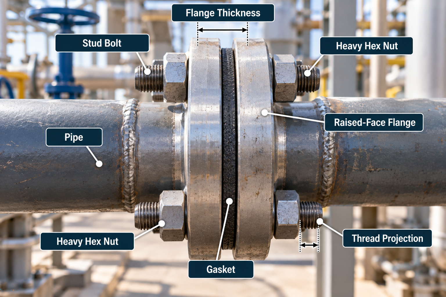
Worked Stud Length Example
Illustrative Stud Length Stack-Up
Practical interpretation: This is not an ASME-required stud length. The commercial length chosen must satisfy the actual specification and length convention.
Raised-Face vs. RTJ Stud Length
RF is raised face and RTJ is ring-type joint. The joint geometry changes the stack, so RF and RTJ do not always use the same stud length. The reference table lists separate lengths where they differ, for example NPS 4 Class 300: 4-1/2 in. for RF and 5 in. for RTJ. At Class 150, RTJ lengths are not listed for NPS 1/2 and 3/4.
| NPS | 1/16 in. RF Length | RTJ Length |
|---|---|---|
| 2″ | 3-1/2″ | 4″ |
| 4″ | 4-1/2″ | 5″ |
| 8″ | 5-1/2″ | 6″ |
| 12″ | 6-3/4″ | 7-1/4″ |
Equipment for Your Project
Affiliate disclosure: As an Amazon Associate, ConcreteCalculate earns from qualifying purchases. We may also earn a commission from other affiliate links at no additional cost to you.
Flange Bolt Thread Size and Pitch
Thread size is written as diameter-threads per inch. Think about nominal diameter, threads per inch, the UNC or other specified series, and the thread class. ASME B1.1-2024 is the technical reference. The table lists common UNC designations only; project and bolting specifications govern. See the Thread Size Chart and the UNC Thread Chart.
| Nominal Stud Diameter (in.) | Common UNC Designation |
|---|---|
| 1/2 | 1/2-13 |
| 5/8 | 5/8-11 |
| 3/4 | 3/4-10 |
| 7/8 | 7/8-9 |
| 1 | 1-8 |
| 1-1/8 | 1-1/8-7 |
| 1-1/4 | 1-1/4-7 |
| 1-1/2 | 1-1/2-6 |
ASTM A193 Flange Stud Materials
ASTM A193/A193M covers alloy-steel and stainless-steel bolting materials for pressure vessels, valves, flanges and fittings in high-temperature or high-pressure service, or other special-purpose applications. It lists several grades, ferritic and austenitic. Grade B7 (chromium-molybdenum alloy steel) is a common example, but A193 is not simply “the B7 standard”. ASTM lists A193/A193M-26 as the active edition. Not every flange uses A193 B7.
ASTM A194 Flange Nuts
ASTM A194/A194M-26 covers carbon, alloy, and martensitic and austenitic stainless steel nuts for bolts for high-pressure or high-temperature service, in sizes 1/4 through 4 in. A193 B7 studs are commonly paired with A194 Grade 2H nuts, and A193 B8 studs with Grade 8 nuts, but that pairing is an application and specification choice, not a universal B16.5 requirement. For general nut dimensions see the Nut Size Chart.
Flange Bolt Material Compatibility
Select the studs and nuts together with the flange material, service temperature, pressure, corrosion, coatings or plating, lubrication and the project piping specification. Do not choose a material from the flange class alone.
Are Washers Used on Flange Studs?
Washer requirements depend on the joint design, the applicable code or specification, the nut-bearing surface, the assembly procedure and engineering requirements. Not every B16.5 joint requires washers. Where hardened washers are specified, use the specified washer type and not ordinary hardware-store washers. For general dimensions see the Washer Size Chart.
Flange Bolt Torque
No single torque is correct for a given NPS and class. Torque depends on the stud diameter and material, nut material, lubricant and friction, gasket, target bolt stress, surface condition and the assembly procedure. It is calculated for the joint, and not read from the flange class. For general fastener torque relationships see the Bolt Torque Chart. Pressure-boundary flange torque must also account for the gasket, bolting material, lubrication, target stress and the applicable assembly procedure.
Torque-Tension Relationship
- T: installation torque
- K: nut factor (friction factor)
- D: nominal fastener diameter
- F: desired bolt preload
K can vary a great deal with lubrication, coatings, thread condition and bearing surfaces. This relationship is educational and not a flange torque prescription. The Bolt Torque Calculator applies the general relationship.
ASME PCC-1 Flange Bolt Tightening
ASME PCC-1-2022 covers assembly of pressure-boundary bolted flange joints with ring-type gaskets that sit entirely within the bolt-hole circle, and the guidelines are used to develop effective joint assembly procedures for the broad range of sizes and services. The topics include joint preparation, alignment, gasket installation, bolting condition, controlled tightening in multiple passes and final verification. This page does not reproduce PCC-1 procedure tables.

Flange Bolt Tightening Sequence
Do not fully tighten one bolt at a time around the circumference. Use a controlled cross-pattern, multi-pass procedure so the gasket compresses progressively and the bolt load develops more uniformly. The passes below are an illustration of the concept, not the PCC-1 sequence.
Illustrative Concept Only
Follow ASME PCC-1 and the project-specific tightening procedure. Do not treat the passes shown as universal load percentages or a universal numbering sequence for every bolt count.
Large-Diameter Flange Bolting: ASME B16.47
B16.5 covers NPS 1/2 to 24 and ASME B16.47 covers NPS 26 to 60, so do not extend this chart to larger flanges. B16.47 has Series A and Series B systems with different bolt patterns, and they must be kept separate by series and class. See the large-diameter section of the Pipe Flange Size Chart.
Common Flange Bolting Mistakes
Selecting bolts by NPS without class
Class changes the bolting.
Confusing bolt-hole diameter with stud diameter
The hole is larger.
Ignoring bolt count
It changes with NPS and class.
Assuming Class 150 and 300 bolt patterns match
Bolt circles differ.
Treating reference stud length as universal
Joint stack-up decides it.
Ignoring RF vs. RTJ
Lengths can differ.
Selecting material from diameter alone
Service and specification matter.
Assuming every flange uses A193 B7
A193 covers several grades.
Using mismatched nuts
Pair them per the specification.
Applying a generic torque value
Torque is joint-specific.
Ignoring lubrication and friction
K varies widely.
Tightening sequentially around the flange
Use a controlled cross-pattern.
Extending B16.5 charts above NPS 24
Use B16.47.
Mixing B16.47 Series A and B
Their bolt patterns differ.
Limitations
What This Chart Does Not Establish
This page is a general flange-bolting reference built on ASME B16.5 bolting values reproduced from a manufacturer, with reference stud lengths for standard raised-face and RTJ joints. It does not establish bolting for Class 400, flanges above NPS 24 or your specific joint, and it gives no torque value. Verify against ASME B16.5 and the project specification. See the Construction Charts hub for related references.
Flange Bolt Size FAQs
What size bolts are used on pipe flanges?
What size bolts does a 2-inch Class 150 flange use?
What bolts does a 4-inch Class 150 flange use?
How many bolts does a 6-inch flange have?
Are Class 150 and Class 300 flange bolts the same?
Is bolt-hole size the same as bolt diameter?
How is flange stud length measured?
Why are RTJ studs sometimes longer?
Should I use bolts or studs on pipe flanges?
What is ASTM A193 B7?
What nuts are used with B7 studs?
Do flange studs need washers?
What torque should flange bolts use?
What tightening sequence should I use?
What standard covers flange bolts?
Save the Flange Bolt Size Chart as a PDF
Use your browser print function to save this reference for the shop, estimating folders and bolting take-offs.