Concrete Control Joints 2026: Spacing, Depth and Placement
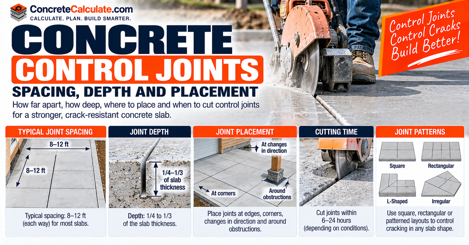
How far apart to space control joints, how deep to cut them, where to place them and when to cut them, including how those decisions change for rectangular and irregular slabs.
Quick Answer
Concrete control joints, also called contraction joints, are planned weakened planes cut or tooled into a slab so that shrinkage cracking happens along a predictable line instead of at random. For an ordinary slab-on-ground, a common planning approach spaces joints at roughly 24 to 36 times the slab thickness, often limited to about 15 feet, cuts them to at least one-quarter of the slab thickness, and times the cut to happen after the surface can withstand the saw but before uncontrolled cracking starts.
These are general planning principles, not universal design requirements. Panel shape, reinforcement, restraint, subgrade friction, environmental conditions and any project-specific engineering plan can all change the right answer for a particular slab.
| Slab Thickness | Calculated 24x to 36x Range | Upper Planning Value After 15 ft Limit |
|---|---|---|
| 3 in | 6 to 9 ft | 9 ft |
| 4 in | 8 to 12 ft | 12 ft |
| 5 in | 10 to 15 ft | 15 ft |
| 6 in | 12 to 18 ft | 15 ft |
| 8 in | 16 to 24 ft | Requires project-specific review rather than forcing a value |
Values are an arithmetic application of NRMCA CIP 6’s general 24 to 36 times slab thickness planning range, with its separately recommended 15-ft upper limit shown alongside. They are planning examples, not automatic design requirements for every slab. For an 8-inch slab, simply clipping the multiplier range to 15 ft or averaging it is not an appropriate substitute for project-specific review.
Check Your Layout
Use the Concrete Joint Calculator to estimate a proposed joint grid for your slab dimensions and check panel proportions before you pour.
Open the Concrete Joint CalculatorIn This Guide
- 1. What Are Concrete Control Joints?
- 2. How Do Concrete Control Joints Work?
- 3. Control Joints vs. Expansion, Isolation and Construction Joints
- 4. Do All Concrete Slabs Need Control Joints?
- 5. Concrete Control Joint Spacing: Quick Reference
- 6. How to Calculate Control Joint Spacing
- 7. What Factors Affect Control Joint Spacing?
- 8. How Deep Should Concrete Control Joints Be?
- 9. Control Joint Depth Chart by Slab Thickness
- 10. How Wide Should a Concrete Control Joint Be?
- 11. Where Should Control Joints Be Placed?
- 12. Square vs. Rectangular Panels: The 1.5:1 Guideline
- 13. How to Lay Out Control Joints on a Rectangular Slab
- 14. Control Joints Around Corners, Columns and Openings
- 15. Control Joint Layout for L-Shaped and Irregular Slabs
- 16. Control Joints for Driveways, Patios, Sidewalks and Garage Floors
- 17. Control Joints Near Walls, Foundations and Existing Slabs
- 18. When Should You Cut Control Joints in New Concrete?
- 19. Early-Entry vs. Conventional Saw Cutting
- 20. Tooled Control Joints vs. Saw-Cut Joints
- 21. How to Mark and Cut Concrete Control Joints
- 22. How Weather Changes Saw-Cutting Time
- 23. What Happens If You Cut Control Joints Too Early or Too Late?
- 24. Do Rebar, Wire Mesh or Fibers Eliminate the Need for Control Joints?
- 25. Should Concrete Control Joints Be Filled or Sealed?
- 26. Common Control Joint Problems and How to Fix Them
- 27. Control Joint Installation Cost and Quantity Estimation
- 28. Concrete Control Joints FAQs
1. What Are Concrete Control Joints?
A concrete control joint, also called a contraction joint, is a planned groove cut or formed into a slab to create a deliberately weakened plane. As the concrete shrinks and contracts, it’s meant to crack along that weakened line rather than at a random, unpredictable location on the surface.
The core planning principles are straightforward to state, though every one of them needs qualification for a specific project. Spacing is commonly planned at roughly 24 to 36 times the slab thickness, often capped around 15 feet. Depth is commonly at least one-quarter of the slab thickness. Timing means cutting after the surface can take the saw without raveling, but before the slab develops an uncontrolled crack on its own. These are general guidelines for ordinary slabs-on-ground, not fixed rules that apply identically to every project.
What This Guide Covers
This article focuses on understanding, planning, cutting, installing and maintaining control joints in typical residential and light commercial slabs-on-ground. For a dedicated reference table of expansion joint spacing values, see the Expansion Joint Spacing Chart. For a calculator that checks your specific proposed grid, see the Concrete Joint Calculator.
2. How Do Concrete Control Joints Work?
Concrete shrinks slightly as it cures and dries, a process called drying shrinkage. It also expands and contracts with temperature changes. Meanwhile, friction with the subgrade beneath the slab, along with any reinforcement or restraint at the edges, resists that movement. Concrete has comparatively low tensile strength, meaning it resists being pulled apart far less effectively than it resists being crushed, so when shrinkage and restraint combine to create enough tensile stress, the concrete cracks.
The groove reduces the slab’s cross-sectional thickness at that specific point, concentrating stress there so the crack forms beneath the visible cut rather than somewhere else on the surface. It’s important to be clear about what this does and doesn’t accomplish: a properly planned and cut joint encourages cracking at a chosen, hidden location. It does not prevent the concrete from cracking altogether, and it doesn’t guarantee that every crack on the slab will occur exactly at a joint.
3. Control Joints vs. Expansion, Isolation and Construction Joints
These four joint types are often confused with each other, but they solve different problems.
| Joint Type | Primary Purpose | Typical Detail | Where It Belongs |
|---|---|---|---|
| Contraction/control | Encourage shrinkage cracking at planned locations | Partial-depth groove or approved formed joint | Within a jointed slab |
| Isolation | Permit independent movement between elements | Full-depth separation with appropriate filler | Around columns, walls and other restraints when required |
| Construction | Define the boundary between separate placements | Designed interface, sometimes with load-transfer devices | At planned pour limits or interruptions |
Control joints only go partway through the slab and are meant to let cracking happen in a controlled place, while remaining part of one continuous placement. An isolation joint, sometimes loosely called an expansion joint, is a full-depth separation that lets a slab move independently from an adjoining restraint such as a column, wall or existing slab. A construction joint simply marks where one day’s concrete placement stopped and the next began, and it may include load-transfer devices such as dowels depending on the application. These terms are not interchangeable, and calling every full-depth separation an expansion joint blurs an important distinction. A dedicated ConcreteCalculate comparison guide will expand on expansion and isolation joint construction in more depth.
4. Do All Concrete Slabs Need Control Joints?
Most typical residential and light commercial slabs-on-ground benefit from a planned control joint layout, since ordinary concrete without special design measures will shrink and is likely to crack somewhere as it cures.
That said, not every concrete system follows the same rulebook. Specially engineered jointless floors, continuously reinforced systems, post-tensioned slabs and certain structural designs use different approaches to manage shrinkage and cracking, sometimes eliminating conventional control joints altogether in favor of other design measures. Suspended slabs, topping slabs over structural decks and structural foundation elements also follow their own engineering requirements rather than the general slab-on-ground spacing formulas discussed in this guide. Where a project has an engineer’s stamped joint plan, that plan takes precedence over the general planning guidance in this article.
5. Concrete Control Joint Spacing: Quick Reference
The table at the top of this guide gives the central spacing reference most readers are looking for. It’s repeated here with its source and assumptions for anyone linking directly to this section.
NRMCA CIP 6, Joints in Concrete Slabs on Grade, recommends a general planning relationship of 24 to 36 times the slab thickness for maximum joint spacing, along with a separate recommendation to limit spacing to a maximum of 15 feet. For a 4-inch slab, that works out to roughly 8 to 12 feet between joints. These figures are meant as general planning guidance for ordinary slabs-on-ground, and they should be checked against panel shape, project-specific design factors and any applicable engineering requirements before being finalized for a real project.
6. How to Calculate Control Joint Spacing
The arithmetic behind the spacing table is simple once you know the multiplier being used.
Spacing Formula
S (ft) = k x [T (in) / 12]
Where S is joint spacing in feet, T is slab thickness in inches, and k is a selected planning multiplier, generally between 24 and 36, subject to the applicable design and spacing limits for your project.
Worked Example: 4-Inch Slab
Using k = 24: S = 24 x (4 / 12) = 24 x 0.333 = 8 ft
Using k = 36: S = 36 x (4 / 12) = 36 x 0.333 = 12 ft
Result: a 4-inch slab produces a calculated range of roughly 8 to 12 feet between joints.
What it means: this range tells you a starting point, not your final layout. The next step is checking that range against your actual slab dimensions to see what panel shape it produces, which is covered later in this guide under the aspect ratio and layout sections.
7. What Factors Affect Control Joint Spacing?
The 24 to 36 times thickness relationship is a starting planning tool, not the full picture. ACI 302.1R-15 identifies a range of factors that influence how a specific slab actually behaves and, in turn, what spacing is appropriate for it.
- Slab thickness: the basic input to the spacing formula itself
- Concrete mixture shrinkage potential: mixtures with higher shrinkage tendencies may warrant closer spacing
- Base friction: a subgrade or base material that restrains slab movement more can increase the tendency to crack between joints
- Restraint: reinforcement, adjoining construction, columns and other fixed elements all restrain how freely the slab can move
- Reinforcement: the type and amount of steel or fiber reinforcement changes how shrinkage stress is distributed
- Loading: anticipated traffic and load types can influence appropriate panel sizing
- Curing: curing method and duration affect how much and how quickly shrinkage develops
- Temperature and environmental exposure: larger temperature swings and certain climates can increase the case for closer joint spacing
Closer spacing than the calculated maximum can be a reasonable choice when several of these factors point toward higher shrinkage or restraint. Specialized slabs, such as those with heavy structural loading, unusual geometry or engineered jointing systems, need their own project-specific design rather than a general residential spacing formula.
8. How Deep Should Concrete Control Joints Be?
The conventional planning relationship calls for a groove depth of at least one-quarter of the slab thickness. NRMCA CIP 6 specifies this quarter-depth minimum and additionally states the groove should never be less than 1 inch deep, even on thinner slabs where a quarter of the thickness would work out to less than that.
Depth matters because an inadequate groove may simply fail to concentrate enough stress at that location, in which case the slab can crack somewhere else instead, defeating the purpose of cutting the joint at all. Early-entry saw systems, which cut shortly after finishing using shallower blades run at higher speed, can have different manufacturer-specified depth requirements than conventional wet-cut saws, so always check the specific equipment’s documented requirements rather than assuming the same quarter-depth rule applies identically.
Check Before You Cut
Never cut a control joint without first confirming what’s beneath the surface at that location. Reinforcement, embedded utilities, radiant heating elements or post-tensioning tendons can all be damaged by a saw cut placed without checking. Consult the approved slab plans, and where uncertain, have the location verified before cutting.
9. Control Joint Depth Chart by Slab Thickness
| Slab Thickness | One-Quarter Depth | Conventional Planning Depth |
|---|---|---|
| 3 in | 0.75 in | At least 1 in under cited CIP 6 guidance |
| 4 in | 1 in | 1 in |
| 5 in | 1.25 in | 1.25 in |
| 6 in | 1.5 in | 1.5 in |
| 8 in | 2 in | 2 in |
This table applies to conventional contraction grooves following NRMCA CIP 6’s general guidance. Early-entry saw systems and specialized pavement designs may specify different minimum depths, so always check the applicable manufacturer or project specification.
10. How Wide Should a Concrete Control Joint Be?
Groove width isn’t governed by a single fixed rule the way depth is, since it depends on the forming or sawing method used, desired appearance, expected traffic and whether the joint will receive a filler or sealant.
A basic saw cut made purely to create a crack-inducing weakened plane can be quite narrow, often just the width of the saw blade. Where a joint is intended to receive a sealant, a separate, wider reservoir cut is sometimes made near the surface to hold the sealant material, while the narrower, deeper cut below continues to do the work of controlling crack location. It’s worth being clear that this groove width discussion is about a control joint’s sealant reservoir, not the same thing as the width of a full-depth isolation joint, which is a separate detail serving a different purpose, as described earlier in this guide.
11. Where Should Control Joints Be Placed?
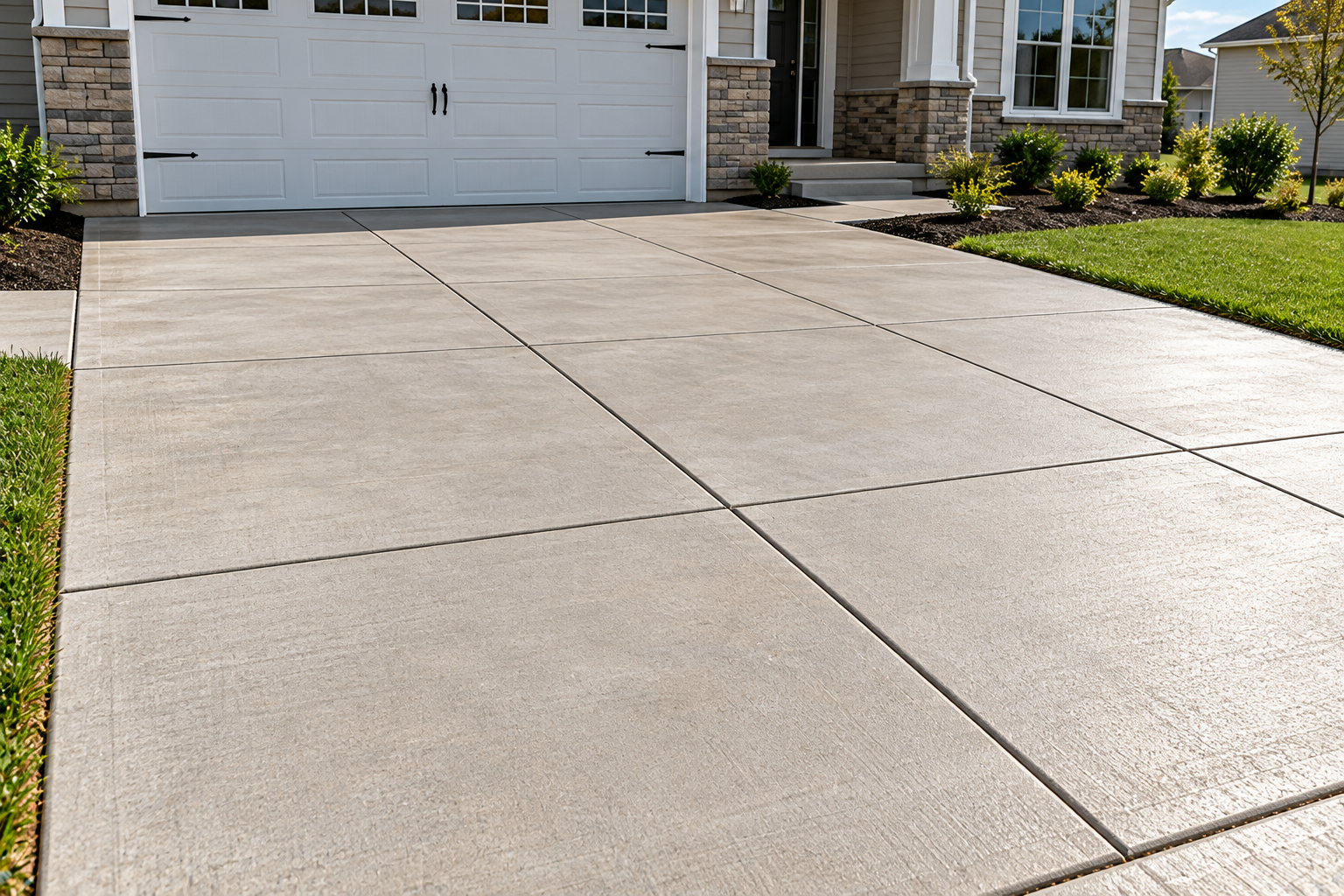
A control joint layout works best as a complete grid planned across the entire slab, considering its perimeter, any interior columns or openings, its overall dimensions and any points of restraint, rather than a handful of cuts added as an afterthought.
Plan Before You Pour
The single most important placement principle is deciding joint locations before the concrete is poured, not after cracks appear. Once a slab has already cracked randomly, cutting a joint afterward does not undo that crack. Planning the full grid in advance, marking it on the forms, and cutting to that plan is what actually gives you control over where cracking happens.
12. Square vs. Rectangular Panels: The 1.5:1 Guideline
Spacing distance alone doesn’t guarantee a good joint layout. Panel shape matters just as much, and it’s easy to satisfy the spacing range while still creating long, narrow panels that are prone to cracking.
Aspect Ratio Formula
R = Longer Panel Dimension / Shorter Panel Dimension
ACI 302.1R-15 recommends square panels as the preferred shape, expressed as a 1:1 ratio, and identifies a maximum aspect ratio of 1.5:1 for applicable slab panel categories. Panels shaped like an L or a T are also specifically discouraged, since these geometries concentrate stress at the inside corner.
It’s worth being direct about what this ratio can and can’t tell you. Meeting the 1.5:1 guideline is a layout consideration that reduces the likelihood of a panel cracking in an uncontrolled way due to its shape, not a guarantee that the panel will remain crack-free. Spacing and aspect ratio need to be checked together, since a distance that looks acceptable on paper can still produce a poorly proportioned panel once you account for the slab’s actual overall dimensions.
13. How to Lay Out Control Joints on a Rectangular Slab
Here’s a complete illustrated example using a 20 by 12-foot slab at an assumed 4-inch thickness, showing how spacing and panel shape are checked together rather than separately.
Using the 4-inch slab spacing range of roughly 8 to 12 feet calculated earlier, a simple grid dividing the 20-foot direction into three equal sections and the 12-foot direction into two equal sections produces six panels, each approximately 6.67 by 6 feet.
Checking the Layout
Panel size: 20 ft / 3 = 6.67 ft, and 12 ft / 2 = 6 ft
Aspect ratio: 6.67 / 6 = 1.11:1, which is well within the 1.5:1 maximum and close to the preferred square shape
Interior joint length: two interior cuts run across the 12-ft width direction, each 20 ft long, contributing 2 x 20 = 40 linear ft… but wait, the layout described divides the 12-ft width into two sections, meaning one interior cut runs the full 20-ft length. It also divides the 20-ft length into three sections, meaning two interior cuts each run the full 12-ft width. That gives two 12-ft runs (24 linear ft) plus one 20-ft run (20 linear ft), for 44 linear ft of interior saw cuts total.
This 44 linear feet figure and the panel dimensions above are a mathematical layout example based on the stated assumptions. They are not a structural drawing and not a universal recommendation for every 20 by 12-foot slab, since actual joint placement should also account for any columns, openings, drains or restraint conditions specific to that project.
14. Control Joints Around Corners, Columns and Openings
Inside corners, columns, drains, pits and other changes in slab geometry all concentrate stress in ways that a simple rectangular grid doesn’t automatically address.
Re-entrant corners, meaning inside corners formed where an L or T shape cuts into a slab, are a particularly common location for cracks to originate, because stress concentrates at that inside point regardless of where the nearest planned joint happens to be. A joint pattern that ignores this tendency can leave a slab vulnerable to cracking right at the corner even if the rest of the grid looks reasonable.
Columns typically need isolation from the surrounding slab rather than an ordinary contraction joint, since the column is a fixed restraint that the slab needs to move independently around. This is a different detail from the contraction-joint layout discussed throughout most of this guide, and it’s worth treating column isolation as its own planning item rather than assuming the nearest control joint automatically handles it.
15. Control Joint Layout for L-Shaped and Irregular Slabs
An irregular slab can usually be planned by mentally dividing it into a set of simpler rectangular regions, then aligning the joint grid so the resulting panels stay reasonably square rather than becoming L- or T-shaped themselves.
For an L-shaped patio, for example, one practical approach is to draw a joint straight across the inside corner, splitting the L into two rectangles. Each rectangle can then be jointed using the same spacing and aspect ratio checks used for any simple rectangular slab. The inside corner itself, the re-entrant corner, is the point that deserves the closest attention and often benefits from a specific design detail rather than simply extending the standard grid through it. This is best treated as a plausible jointing concept for planning purposes, with the final layout reviewed by whoever is responsible for the project’s design, since the right detail at a re-entrant corner can vary with slab thickness, reinforcement and expected loading.
16. Control Joints for Driveways, Patios, Sidewalks and Garage Floors
The same underlying spacing, depth and aspect ratio principles apply across these common residential applications, but each one has its own practical wrinkles worth planning around.
| Application | Key Consideration |
|---|---|
| Sidewalks | Long and narrow by nature, so spacing along the length matters more than width; width alone rarely allows a square panel |
| Driveways | Wider than sidewalks, generally allowing more square panel options, but vehicle turning areas and aprons need their own layout review |
| Patios | Often restrained along one or more edges by an adjoining house foundation, which affects joint and isolation planning at that edge |
| Garage floors | May need special treatment at door openings, floor drains and any interior columns, in addition to the general slab grid |
None of these project types should be assigned one fixed spacing value based on their name alone. A sidewalk and a driveway of the same slab thickness follow the same spacing formula; what differs is how that spacing interacts with the slab’s actual width and any application-specific features like drains or door openings. For layout and material planning on these applications, see the guide to pouring a concrete driveway and the Concrete Driveway Calculator.
17. Control Joints Near Walls, Foundations and Existing Slabs
Where a new slab meets a wall, a house foundation or an existing slab, a contraction joint is often the wrong detail entirely. These locations frequently call for a full-depth isolation joint instead, since the new slab needs to move independently from the adjoining, already-fixed element rather than staying connected to it through a partial-depth groove.
A common example is where a driveway meets a garage floor slab, or where a patio meets an existing house foundation. In both cases, the adjoining structure is essentially a fixed restraint, and tying the new slab to it with anything other than an isolation joint can create unwanted restraint that concentrates stress right at that connection. The dedicated ConcreteCalculate comparison guide on expansion versus control joints will expand further on this distinction and its construction details.
18. When Should You Cut Control Joints in New Concrete?
Saw-cutting timing is a balancing act between two competing risks: cutting too soon, which can ravel or tear the surface because the concrete hasn’t gained enough strength, and cutting too late, after the slab has already developed an uncontrolled crack on its own.
According to ACI’s technical guidance on this question, saw-cutting should happen before random drying-shrinkage cracks form and when the surface is firm enough that the blade won’t damage it. As general planning examples, conventional saw cuts are commonly made within roughly 4 to 12 hours after placement depending on temperature and weather, while early-entry saw systems are commonly used somewhat sooner, in ranges that can run from about 1 hour in hot weather up to around 4 to 6 hours in cooler weather. These figures are planning examples pulled from technical guidance, not guaranteed safe cutting windows for your specific slab. The actual right moment to cut depends on how the surface actually feels and responds that day, not strictly on the clock.
19. Early-Entry vs. Conventional Saw Cutting
| Method | When Generally Performed | Depth Consideration | Main Risk |
|---|---|---|---|
| Tooled groove | During finishing while concrete is plastic | Required finished groove depth | Grooves that are too shallow or close over |
| Early-entry saw | Shortly after finishing, when the equipment and concrete allow | Approved system-specific depth | Cutting too early or misunderstanding the equipment’s depth requirements |
| Conventional saw | After adequate surface firmness, before random cracking | Typically quarter-depth under cited guidance | Raveling if too early; uncontrolled cracking if too late |
Actual timing depends on jobsite conditions, mix design, temperature and equipment, and should not be scheduled purely by a universal number of hours. Always follow the specific manufacturer instructions and blade specifications for the saw and slab in question.
Early-entry saws use a specially designed, shallower blade run at higher speed, allowing crews to cut sooner after finishing than a conventional wet saw typically allows. Conventional saws are the more familiar wet-cut equipment, generally brought in once the surface has had more time to firm up. Both methods can achieve a properly functioning control joint, but the equipment, blade specifications, aggregate hardness, concrete condition and project requirements all influence which one is appropriate and how the procedure should actually be carried out on a given job.
20. Tooled Control Joints vs. Saw-Cut Joints
Tooled joints are formed by hand during finishing, while the concrete is still plastic, using a jointing tool run along a straightedge to press a groove into the surface. Saw-cut joints, by contrast, are cut into the concrete after it has hardened enough to firm up, using either an early-entry or conventional saw.
The two approaches differ in equipment, timing and appearance. Tooled joints tend to have a slightly rounded, more finished look and don’t require power equipment, making them a practical choice for smaller residential placements like sidewalks and patios. Saw-cut joints tend to produce a cleaner, straighter line, especially over longer runs, and are common on driveways and larger slabs. Neither method is universally preferable. The right choice depends on the project’s scale, the finishing crew’s equipment and preferences, and the desired final appearance.
21. How to Mark and Cut Concrete Control Joints
Once the layout has been planned, the actual cutting sequence follows a fairly consistent process.
- Confirm the approved layout. Verify the joint plan against the slab drawings, including spacing, panel shapes and any special details at corners or restraints.
- Mark the locations. Snap chalk lines or otherwise mark the exact joint locations on the slab surface before cutting begins.
- Select suitable equipment. Choose an early-entry or conventional saw appropriate to the slab’s condition, thickness and project schedule.
- Check cutting readiness. Test the surface to confirm it will withstand the saw without raveling, rather than relying solely on elapsed time.
- Make continuous cuts to the required depth. Cut each joint in one continuous pass along the marked line to the specified depth.
- Protect or clean the finished joints. Remove slurry and debris from the cut, and protect the joint as specified until any further filling or sealing takes place.
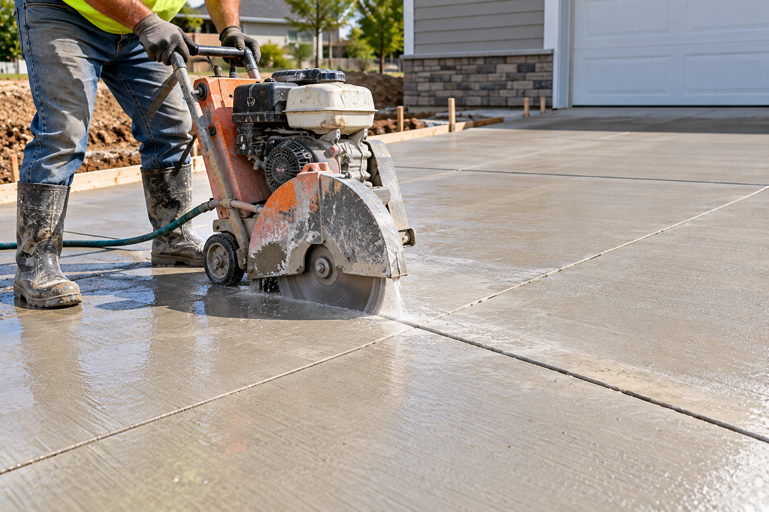
Cutting Hazards to Manage
Both wet and dry cutting carry hazards worth planning for. Wet cutting introduces water and electrical equipment together, so proper grounding and cord management matter. Dry cutting with an early-entry saw generates dust, which relates to the same respirable crystalline silica concerns that apply to other concrete cutting and grinding work. Any cutting near known reinforcement, embedded utilities or other components should proceed carefully to avoid damaging them.
22. How Weather Changes Saw-Cutting Time
Temperature, direct sunlight, wind and humidity all influence how quickly a slab firms up enough to be cut, along with how quickly it might develop an uncontrolled crack if cutting is delayed.
Hot, sunny and windy conditions accelerate surface drying and early strength gain, generally shifting the cutting window earlier, sometimes considerably. Cool, humid or shaded conditions slow that process down, generally allowing more time before cutting becomes necessary, but also more time before the surface is ready to withstand the saw. The concrete mixture itself, including its cement content and any admixtures, also affects how quickly it develops adequate firmness. For broader guidance on how weather affects concrete work generally, see Best Time to Pour Concrete. Detailed hot- and cold-weather concreting procedures are covered on their own dedicated ConcreteCalculate guides rather than repeated here.
23. What Happens If You Cut Control Joints Too Early or Too Late?
Cutting too early, before the concrete has gained enough strength, commonly causes raveling, where the saw blade dislodges aggregate and tears the edges of the cut rather than producing a clean groove. This damages the joint’s appearance and can weaken the edge over time.
Cutting too late, after the slab has already developed a random crack on its own, means the joint has effectively missed its purpose. The concrete has already found its own place to relieve stress, and a saw cut made after the fact will not erase that existing crack. At best, a late cut might intercept a crack that hasn’t fully developed yet; at worst, you end up with both the original random crack and a joint that never actually controlled anything.
24. Do Rebar, Wire Mesh or Fibers Eliminate the Need for Control Joints?
No. Reinforcement changes how a slab behaves once cracking occurs, but it doesn’t stop the concrete from shrinking in the first place. Rebar, welded wire mesh and fiber reinforcement can help hold a crack together and limit how wide it opens, which is a genuinely useful benefit, but none of them prevent the underlying shrinkage that drives the need for planned control joints.
It’s also worth distinguishing ordinary distributed reinforcement, the kind used broadly across a typical slab-on-ground, from special structural reinforcement designs that follow their own engineered approach to crack control. Where reinforcement crosses a control joint, its continuity through that joint must follow the approved design detail rather than running through unbroken by default. ACI specifically cautions against reinforcement continuity that ends up restraining the very movement the contraction joint is meant to allow, since that restraint can defeat the purpose of the joint. For more on reinforcement generally, see Does Concrete Need Rebar? and the Concrete Reinforcement Calculator.
25. Should Concrete Control Joints Be Filled or Sealed?
Whether to fill or seal a control joint depends on the specific application, and there’s no single answer that fits every slab.
Many ordinary residential exterior slabs, such as sidewalks and patios, can be left with unsealed joints without significant issue, since their main function, controlling crack location, doesn’t strictly require a sealant to work. Flexible sealants become appropriate where keeping out water and debris matters more, such as at joints exposed to significant moisture or where appearance is a priority. Hard-wheeled industrial or commercial floors, which see forklift or cart traffic, often benefit from a semi-rigid filler instead of a flexible sealant, since a rigid filler better protects the joint edges from spalling under that kind of concentrated wheel loading.
Filler and sealant selection ultimately depends on anticipated joint movement, traffic type, moisture exposure and the joint’s actual geometry, including its width and depth. Use the Sealant Calculator to estimate the appropriate quantity for your specific joint dimensions once you’ve selected a suitable product.
26. Common Control Joint Problems and How to Fix Them
| Observed Problem | Possible Reason | What to Inspect or Do Next |
|---|---|---|
| Random crack between joints | Spacing, shrinkage or restraint | Check layout, joint depth, subgrade and movement |
| Crack at an inside corner | Stress concentration | Review geometry and joint positioning |
| Raveled cut edges | Premature cutting or unsuitable equipment | Assess cutting method and necessary edge repair |
| Crack missing the saw cut | Late cutting, insufficient depth or restraint | Investigate the cause before attempting correction |
| Damaged joint edges under traffic | Inadequate load transfer or unsuitable joint protection | Professional evaluation of edge support and filling |
| Failed sealant | Incorrect preparation or unsuitable sealant | Clean and reseal with a compatible system where appropriate |
These corrective steps point toward the right next investigation, not a guaranteed permanent fix for every situation. A crack that has already missed the planned saw cut, for instance, is best understood by figuring out why it happened before deciding whether any correction is realistic or necessary. For a broader discussion of unexpected cracking patterns and causes, see Why Is My Concrete Cracking? and How to Fix Cracked Concrete.
27. Control Joint Installation Cost and Quantity Estimation
Estimating control joint cost starts with calculating the total linear footage of joints from your layout plan, then pricing the separate cost components involved: saw-cutting labor and equipment, hand-tooling labor where applicable, joint filling or sealant material, site access and any necessary surface preparation.
| Measurement | Illustrative Value |
|---|---|
| Slab length | 20 ft |
| Slab width | 12 ft |
| Slab thickness | 4 in |
| Number of panels | 6 |
| Approximate panel size | 6.67 x 6 ft |
| Long-side to short-side ratio | 1.11:1 |
| Two 12-ft interior runs | 24 linear ft |
| One 20-ft interior run | 20 linear ft |
| Total interior joints | 44 linear ft |
This worksheet excludes the slab perimeter, since only interior contraction joints are counted here. Isolation or construction joints, where required around the slab’s edges or at restraints, should be measured and accounted for separately from this interior contraction-joint total.
Published national cutting-cost ranges vary widely and change with material and labor markets, so they’re not a substitute for an actual local contractor quotation based on your specific slab, access conditions and joint plan. Request quotes referencing your calculated linear footage for an accurate comparison between contractors.
Estimate Your Joint Layout and Quantities
Use the Concrete Joint Calculator to check spacing and panel proportions for your own slab dimensions, or the Control Joint Calculator for an alternative calculation approach.
Open the Concrete Joint Calculator28. Concrete Control Joints FAQs
How far apart should concrete control joints be?
A common planning approach spaces joints at roughly 24 to 36 times the slab thickness, often limited to about 15 feet for typical residential slabs. For a 4-inch slab, that works out to about 8 to 12 feet. This range should also be checked against panel shape and any project-specific factors before finalizing a layout.
How deep should control joints be cut?
Conventional guidance calls for a groove depth of at least one-quarter of the slab thickness, with a minimum of 1 inch regardless of slab thickness under commonly cited NRMCA guidance. Early-entry saw systems may follow different manufacturer-specified depths.
When should you cut control joints in concrete?
Cutting should happen after the surface is firm enough to withstand the saw without raveling, but before the slab develops an uncontrolled crack on its own. Conventional saws are commonly used within roughly 4 to 12 hours after placement, and early-entry saws somewhat sooner, though actual timing depends heavily on weather and jobsite conditions rather than the clock alone.
Do control joints prevent every crack?
No. Control joints encourage cracking to happen at a planned location rather than at random, but they don’t eliminate the concrete’s tendency to shrink and crack. Cracks can still occur between joints, especially if spacing, panel shape or an underlying restraint issue wasn’t properly addressed.
Can you cut control joints into an existing slab?
Cutting a joint after a slab has already cracked randomly will not remove that existing crack. If you’re trying to add joints to an uncut existing slab before it cracks, that’s a different situation from repairing a slab that has already developed random cracking, and the right approach depends on the current condition of that specific slab.
Should control joints be sealed?
It depends on the application. Many residential exterior slabs can be left unsealed without significant issue, while joints exposed to more moisture, or industrial floors seeing hard-wheeled traffic, often benefit from a flexible sealant or semi-rigid filler respectively. Selection depends on movement, traffic, moisture and joint geometry.
Do I still need control joints if my slab has rebar or fiber reinforcement?
Yes. Reinforcement helps control crack width and hold a crack together once it forms, but it doesn’t stop the concrete from shrinking, so planned control joints are still needed to encourage cracking at chosen locations.
Where should control joints be positioned on a slab?
Joints should form a planned grid across the slab’s full perimeter and interior, addressing dimensions, any restraints such as columns, and stress concentration points like re-entrant corners, decided before the concrete is poured rather than after cracking appears.
What if my slab was poured without a proper joint layout?
An incorrectly jointed slab that has already cracked randomly generally can’t be corrected by cutting new joints after the fact, since the existing cracks won’t disappear. Depending on the extent of cracking and its appearance and performance impact, options may range from accepting the existing cracks as a cosmetic issue to more involved repair or resurfacing, which is worth discussing with a qualified concrete professional for your specific slab.
References
- American Concrete Institute, ACI 302.1R-15, Guide to Concrete Floor and Slab Construction, Chapter 5. Used for design factors affecting joint spacing, panel aspect ratio guidance, restraint considerations, reinforcement continuity and joint filling.
- National Ready Mixed Concrete Association, CIP 6, Joints in Concrete Slabs on Grade. Used as the primary homeowner-facing reference for the 24 to 36 times thickness spacing relationship, the 15-ft recommended upper limit, and conventional quarter-depth groove guidance with its 1-inch minimum.
- American Concrete Institute, Technical FAQ: When Should Saw Cuts Be Made on a Concrete Slab? Used for field timing guidance, conventional and early-entry sawing windows, and the emphasis on surface readiness and weather conditions over fixed hour counts.
- American Concrete Institute, ACI 224.3R, Joints in Concrete Construction. Used as an additional reference for joint types, detailing practices and the distinction between contraction, isolation and construction joints. Confirm the applicable edition when preparing technical citations for further use.
Plan Your Slab’s Joint Layout
Check your slab dimensions against appropriate spacing and panel proportions before you pour, so your joint plan is ready when the concrete arrives.
Use the Concrete Joint Calculator