Rebar Spacing Chart – Minimum, Maximum & Code Requirements
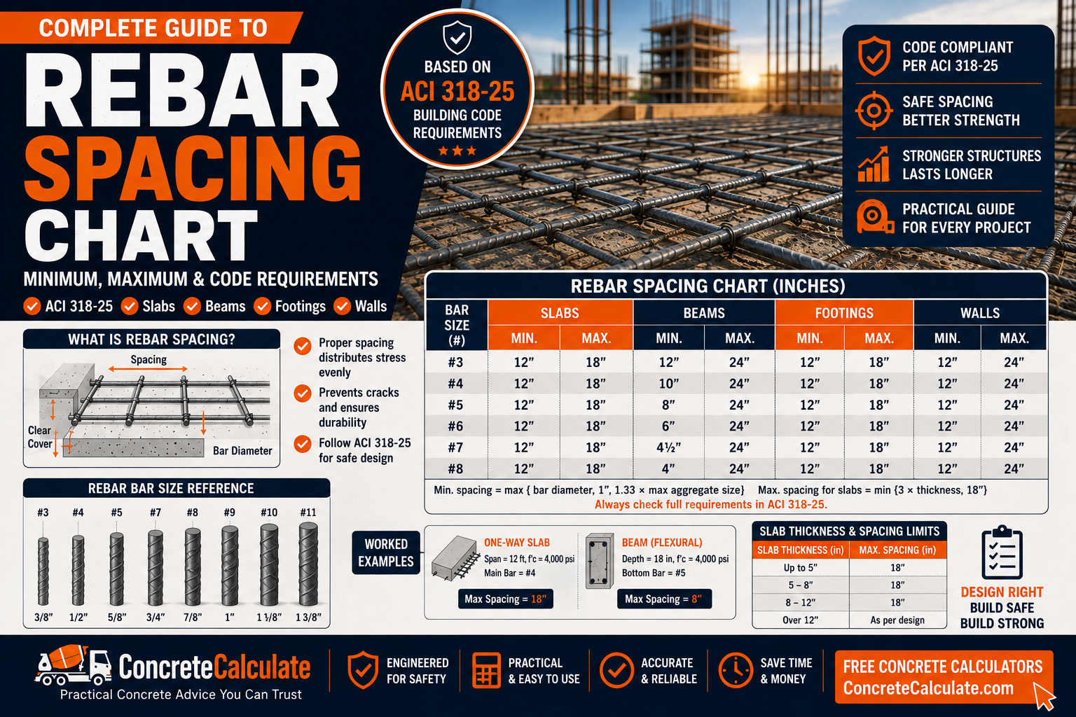
Rebar Spacing Chart
Minimum, Maximum & Code Requirements
The complete rebar spacing reference: minimum clear spacing, maximum spacing by element, clear versus center to center spacing, bar size data, and current ACI CODE-318-25 provisions.
Which code edition governs your project
ACI CODE-318-25 is the current published edition from the American Concrete Institute. The edition that actually governs your project is whichever edition your local building code has adopted, which can lag behind the newest ACI release by several years. Confirm the applicable edition with your building department, engineer of record, or project specifications before finalizing any spacing decision.
Rebar Spacing Chart, Quick Reference
Six distinct spacing concepts control every number on this page. Minimum spacing protects concrete placement. Maximum spacing protects reinforcement performance. Design-required spacing is what an engineer calculates for a specific load. Typical field spacing is a common convention, not a code mandate. Clear spacing is measured bar surface to bar surface. Center to center spacing is measured centerline to centerline.
| Bar Size | Diameter (in.) | Min. Clear Spacing* | Center to Center at Minimum* | Typical Field Options | Application |
|---|---|---|---|---|---|
| #3 | 0.375 | 1.00 in. | 1.375 in. | 12, 16, 18 in. | Temperature/shrinkage steel |
| #4 | 0.500 | 1.00 in. | 1.50 in. | 8, 12, 16, 18 in. | Slabs-on-grade, sidewalks |
| #5 | 0.625 | 1.00 in. | 1.625 in. | 8, 12, 16, 18 in. | Slabs, footings |
| #6 | 0.750 | 1.00 in. | 1.75 in. | 8, 12, 16 in. | Beams, columns, structural slabs |
| #7 | 0.875 | 1.00 in. | 1.875 in. | 6, 8, 12 in. | Beams, columns |
| #8 | 1.000 | 1.00 in. | 2.00 in. | 6, 8, 12 in. | Beams, columns, foundation walls |
| #9 | 1.128 | 1.128 in. | 2.256 in. | 6, 8 in. | Heavy beams and columns |
| #10 | 1.270 | 1.270 in. | 2.54 in. | 6, 8 in. | Heavy columns |
| #11 | 1.410 | 1.410 in. | 2.82 in. | 6, 8 in. | Heavy columns, high-rise members |
*Minimum clear spacing per ACI CODE-318-25 Section 25.2.1, using the greatest of 1 in., bar diameter, or 4/3 times a common 3/4 in. maximum aggregate size. Confirm actual aggregate size and governing spacing from project specifications. Typical field options are construction conventions, not code-mandated maximums; see the maximum spacing section for the values that actually govern.
What Is Rebar Spacing?
Rebar spacing is the distance between parallel reinforcing bars in a concrete member, and it affects structural capacity, crack control, bond, constructability, and material quantity.
| Factor | Why Spacing Matters |
|---|---|
| Structural capacity | Steel amount and distribution across a width affects bending and shear resistance |
| Crack control | Well distributed reinforcement limits shrinkage and flexural crack widths |
| Concrete consolidation | Adequate gaps let coarse aggregate and vibration pass around the steel |
| Bond | Spacing helps concrete fully bond around each bar surface |
| Constructability | Crews need room to tie, support, and place concrete around bars |
| Material quantity | Closer spacing generally means more bars, weight, and labor per square foot |
FHWA’s dual function principle
FHWA guidance describes spacing as having both a minimum function, allowing concrete to be properly placed and consolidated, and a maximum function, supporting reinforcement performance and crack control.
Clear Spacing vs Center to Center Spacing
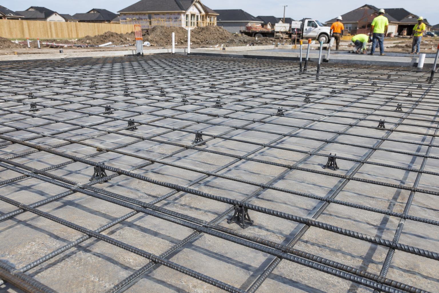
Clear spacing is the gap between bar surfaces. Center to center spacing is the distance between bar centerlines. Confusing the two is the most common rebar spacing mistake.
- Two #6 bars (0.75 in. diameter) with 1.75 in. clear space have a center to center spacing of 2.5 in.
- If a drawing calls out 8 in. spacing for #6 bars measured center to center, the actual clear gap is only 7.25 in.
Which measurement does a code limit use
Minimum spacing provisions such as ACI CODE-318-25 Section 25.2 are written in clear spacing, since that is what controls whether aggregate can pass through. Maximum spacing provisions for flexural and shrinkage reinforcement are generally written in center to center spacing. Always check which one a drawing note references.
Minimum Rebar Spacing Requirements
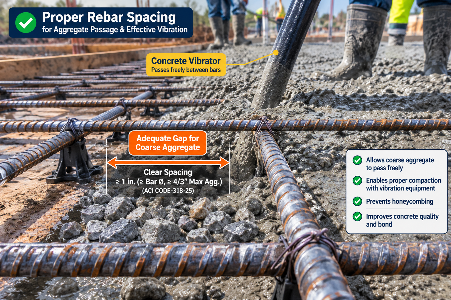
Minimum spacing exists so fresh concrete and coarse aggregate can flow between and around bars during placement and vibration.
| Controlling Value | Requirement |
|---|---|
| Absolute minimum | 1 inch |
| Bar diameter | db (nominal bar diameter) |
| Aggregate based | 4/3 × dagg (maximum aggregate size) |
Whichever of these three values is largest becomes the controlling minimum clear spacing under ACI CODE-318-25 Section 25.2.1, located in Chapter 25, Reinforcement Details. Because the rule depends on aggregate size, the same bar can require different minimum spacing on two different mixes. For reinforcement in two or more horizontal layers, bars in an upper layer must sit directly above the bars in the layer below, with a defined minimum clear vertical distance between layers.
Maximum Rebar Spacing Requirements
There is no single maximum rebar spacing number. Maximum spacing depends on the element, reinforcement purpose, thickness, and applicable code edition.
| Reinforcement Purpose | Governing Concept | Typical Controlling Limit |
|---|---|---|
| One-way slab/beam flexural steel | Distribution of flexural reinforcement | Lesser of 3h and 18 in. |
| Two-way slab, critical sections | Punching and flexural performance | Lesser of 2h and 18 in. |
| Two-way slab, other sections | General distribution | Lesser of 3h and 18 in. |
| Shrinkage and temperature steel | Restrained shrinkage/temperature control | Lesser of 5h and 18 in. |
Do not treat 18 inches as a universal maximum
The 18 inch figure only appears as the upper bound of a “lesser of” comparison against a multiple of member thickness (h). A thin slab is often limited to spacing well under 18 inches. These limits are illustrative of the general ACI 318 framework; confirm exact section numbers against your project’s governing edition.
Rebar Spacing by Structural Element
Each element combines its own minimum spacing (for placement) and maximum spacing (for performance) based on how it behaves structurally.
| Element | Primary Spacing Concern | Key Distinction |
|---|---|---|
| Slabs | Flexural vs shrinkage/temperature maximum spacing | One-way vs two-way limits differ |
| Beams | Minimum clear spacing, multiple layers, skin steel | Stirrup spacing is separate from bar spacing |
| Columns | Longitudinal bar clear spacing | Tie/spiral spacing is a different concept |
| Walls | Vertical and horizontal reinforcement | Boundary regions may need tighter spacing |
| Footings/foundations | Two-way bottom reinforcement | Congestion at column dowels |
| Pavements | Longitudinal steel for CRCP | Governed by FHWA, not building code |
Rebar Spacing for Concrete Slabs
Slab spacing is the highest search intent in this category. One-way and two-way slabs follow different maximum spacing limits, and flexural steel follows different rules than shrinkage/temperature steel.
| Slab Type / Steel Type | Maximum Spacing Basis | Notes |
|---|---|---|
| One-way slab, flexural steel | Lesser of 3h and 18 in. | Further reduced by separate crack-control stress checks |
| Two-way slab, critical sections | Lesser of 2h and 18 in. | Critical sections near supports and midspan |
| Two-way slab, other sections | Lesser of 3h and 18 in. | Elsewhere in the slab |
| Shrinkage/temperature steel (either slab type) | Lesser of 5h and 18 in. | Placed perpendicular to primary one-way flexural steel |
Thicker slabs allow wider maximum spacing since the limit scales with thickness, but thickness alone does not set correct spacing. Bar size, required steel area, exposure, and crack control all interact with thickness in the final design. Do not treat 12, 16, or 18 inch spacing as universal recommendations; see the slab thickness and common layouts sections below.
Rebar Spacing for Beams
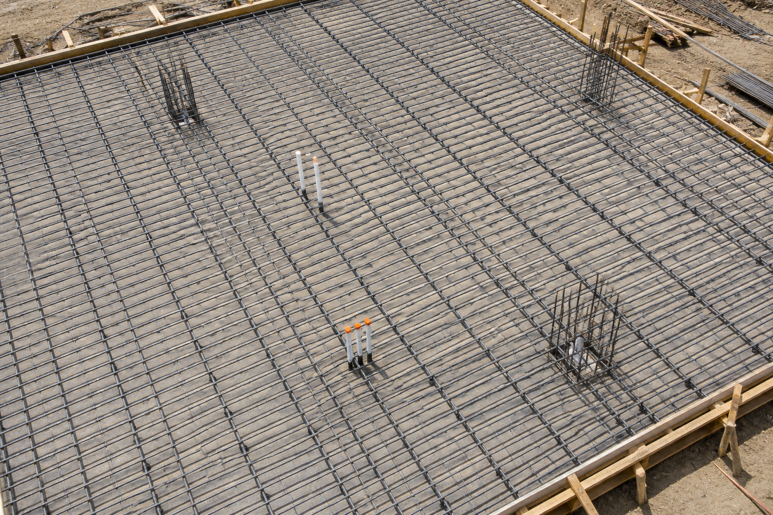
Beam reinforcement involves more distinctions than slabs, since beams often use multiple layers and separate stirrup and skin reinforcement provisions.
| Reinforcement Type | Governing Concept |
|---|---|
| Longitudinal bars (top/bottom) | Minimum clear spacing per Section 25.2, based on bar diameter and aggregate size |
| Multiple layers | Upper layer bars align directly above lower layer, with minimum vertical clear distance |
| Skin reinforcement | Separate provision for deep beams to control side-face cracking |
| Stirrup spacing | Independent shear design calculation, not interchangeable with bar clear spacing |
ACI 318 treats skin reinforcement spacing and primary longitudinal spacing as distinct provisions, and stirrup spacing is calculated from shear demand rather than clearance rules. This page addresses the general spacing concepts only; a full beam design should follow project structural drawings.
Rebar Spacing for Columns
Longitudinal bar spacing and tie or spiral spacing are frequently confused but describe entirely different things.
| Reinforcement | Purpose | Spacing Basis |
|---|---|---|
| Longitudinal bars | Axial and bending resistance | Minimum clear spacing (greatest of 1 in., db, 4/3 dagg) |
| Ties/spirals | Confinement, buckling resistance | Separate structural/seismic calculation, not a clearance rule |
Column congestion, where many large longitudinal bars and closely spaced ties occupy a small cross section, is a common constructability challenge. Adequate clear spacing between longitudinal bars is essential so concrete and aggregate can still reach the column core during placement.
Rebar Spacing for Concrete Walls
Walls typically need both vertical reinforcement for axial and out-of-plane bending, and horizontal reinforcement for shrinkage, temperature, and shear.
| Reinforcement Direction | Typical Role |
|---|---|
| Vertical | Axial load and out-of-plane bending resistance |
| Horizontal | Shrinkage, temperature control, in-plane shear |
| Boundary regions | Additional tighter spacing near wall ends in structural/lateral walls |
Maximum spacing for wall reinforcement is commonly tied to a multiple of wall thickness (h) with an 18 inch upper bound, similar to slabs, but the governing multiple depends on whether the reinforcement functions as primary structural steel or shrinkage/temperature steel.
Rebar Spacing for Footings and Foundations
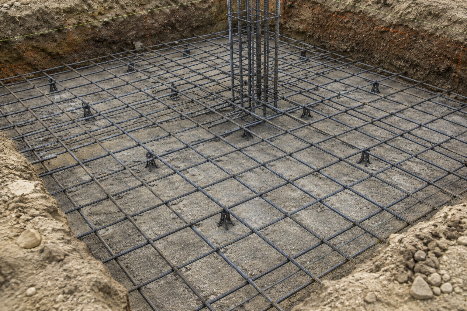
Footings typically use two-way reinforcement at the bottom to resist bending from soil bearing pressure, following the same minimum clear spacing rule as other elements.
Because footings are often thicker and more heavily reinforced than slabs, congestion at footing intersections and column dowel locations deserves particular attention during placement. Foundation walls combine vertical and horizontal reinforcement similar to above-grade walls, while foundation slabs follow slab-type spacing logic. For dimensional footing planning, see the Footing Size Chart.
Rebar Spacing for Concrete Pavements
Pavement reinforcement spacing follows FHWA guidance, which is distinctly different from building structural concrete provisions.
| Limit | FHWA Guidance (CRCP) |
|---|---|
| Minimum longitudinal spacing | Greater of 4 in. or 2.5 × maximum aggregate size |
| Maximum longitudinal spacing | 9 in. center to center |
This 9 inch maximum is far tighter than the 18 inch figures used in building slabs, because continuously reinforced concrete pavement relies on closely spaced steel to hold together a deliberately cracked pavement section. Always confirm whether a project follows building code (ACI 318) or transportation agency (FHWA/AASHTO/state DOT) guidance.
Rebar Spacing by Bar Size
Bar size affects both the minimum clear spacing and the practical spacing options commonly used in the field, based on ASTM A615 dimensions.
| Bar Size | Diameter (in.) | Area (in.2) | Effect on Min. Clear Spacing | Common Context |
|---|---|---|---|---|
| #3 | 0.375 | 0.11 | 1 in. minimum typically governs | Temperature/shrinkage steel, light slabs |
| #4 | 0.500 | 0.20 | 1 in. minimum typically governs | Slabs-on-grade, sidewalks |
| #5 | 0.625 | 0.31 | 1 in. minimum typically governs | Slabs, footings, walls |
| #6 | 0.750 | 0.44 | 1 in. minimum typically governs | Beams, columns, structural slabs |
| #7 | 0.875 | 0.60 | Governs with larger aggregate | Beams, columns |
| #8 | 1.000 | 0.79 | Bar diameter may govern | Beams, columns, foundation walls |
| #9 | 1.128 | 1.00 | Bar diameter governs | Heavy beams and columns |
| #10 | 1.270 | 1.27 | Bar diameter governs | Heavy columns, transfer girders |
| #11 | 1.410 | 1.56 | Bar diameter governs | Heavy columns, high-rise members |
Values are sourced from ASTM A615/A615M, the governing U.S. specification for deformed reinforcing bars. For complete dimensional data and weight per foot, see the Rebar Size Chart and Rebar Weight Chart. For grade and yield strength, see the Rebar Grade Chart.
Rebar Spacing by Slab Thickness
Slab thickness (h) directly scales several maximum spacing limits, which is why thickness and spacing are frequently discussed together.
| Slab Thickness (h) | 2h (Two-Way Critical) | 3h (Flexural/One-Way) | 5h (Shrinkage/Temp) | Governing Flexural Max* |
|---|---|---|---|---|
| 5 in. | 10 in. | 15 in. | 25 in. | 15 in. |
| 6 in. | 12 in. | 18 in. | 30 in. | 18 in. |
| 8 in. | 16 in. | 24 in. | 40 in. | 18 in. |
| 10 in. | 18 in. | 30 in. | 50 in. | 18 in. |
*Governing flexural maximum equals the lesser of the thickness-based value and 18 in. Flexural spacing may be further reduced by separate crack-control provisions tied to reinforcement stress, not shown here. Confirm against the applicable code edition and full design calculation before use. For slab thickness selection itself, see the Concrete Slab Thickness Chart.
Common Slab Layouts Reference
These are common field conventions, not universally approved code values. The correct spacing still depends on thickness, bar size, and the applicable code edition.
| Spacing | Relative Bar Count | General Characteristics |
|---|---|---|
| 6 in. | Highest | Denser distribution, higher material/labor cost |
| 8 in. | High | Common for driveways with moderate vehicle loading |
| 12 in. | Moderate | Frequent field convention for residential slabs |
| 16 in. | Lower | Often paired with larger bars to maintain steel area |
| 18 in. | Lowest | Near the common 18 in. upper bound; check governing maximum |
Rebar Spacing and Reinforcement Area
Spacing and bar size together set how much steel area exists across a given width, which is the foundation of reinforcement design.
- As = reinforcement area per unit width
- Ab = cross-sectional area of one bar
- s = center to center spacing
Worked Example: Area Per Foot of Width
This relationship connects a spacing decision to an actual reinforcement ratio. Use the Rebar Grid Calculator for full grid area, linear footage, and weight, and the Rebar Area Calculator for area-focused calculations.
Rebar Size vs Rebar Spacing
Larger bars at wider spacing are not automatically equivalent to smaller bars at closer spacing, even when total steel area matches closely.
| Layout | Area per Foot | Consideration |
|---|---|---|
| #4 @ 12 in. | 0.20 in.2 | More bars, finer distribution |
| #5 @ 18 in. | ≈0.207 in.2 | Fewer, larger bars, wider crack spacing potential |
Equal area is not equal performance
Nearly identical total area does not mean the two layouts are interchangeable. Distribution, crack width, bond, and development length all depend on bar diameter, not just total area. Substituting bar size and spacing is a structural engineering decision, not a simple area-matching exercise.
Equipment for Your Project
Affiliate disclosure: As an Amazon Associate, ConcreteCalculate earns from qualifying purchases. We may also earn a commission from other affiliate links at no additional cost to you.
Rebar Spacing and Crack Control
Spacing directly influences how cracks form and how wide they become, since closer spacing tends to distribute cracking into many fine cracks rather than a few wide ones.
| Factor | Effect |
|---|---|
| Bar spacing | Closer spacing produces more, finer cracks |
| Bar diameter | Smaller bars distribute reinforcement closer to the surface |
| Reinforcement ratio | Total steel area relative to concrete affects crack width potential |
| Shrinkage/temperature | Generates tensile stress independent of applied load |
ACI 318’s slab provisions explicitly address reinforcement distribution and spacing for crack control, while FHWA pavement guidance separately addresses how spacing affects the cracking behavior that continuously reinforced pavement is designed around.
Rebar Spacing and Concrete Consolidation
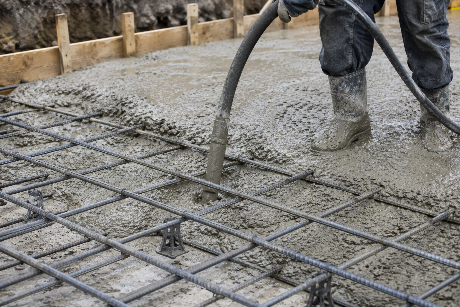
Reinforcement cannot simply be packed as tightly as structurally desirable without considering how concrete will actually flow and consolidate around it.
Concrete flow
Fresh concrete must flow between and around bars to fully encase the reinforcement.
Aggregate passage
Coarse aggregate needs enough clear space to pass through without bridging.
Vibration access
Vibration equipment needs paths through the reinforcement to consolidate the mix.
Voids and honeycombing
Insufficient spacing is a leading cause of visible voids and weak, porous concrete.
This is exactly why ACI CODE-318-25’s minimum spacing provision ties clear spacing to maximum aggregate size; the aggregate has to physically fit through the gap.
Rebar Spacing and Maximum Aggregate Size
Maximum aggregate size is a direct input into the minimum clear spacing calculation under ACI CODE-318-25 Section 25.2.1.
| Max Aggregate Size | 4/3 × Aggregate Value |
|---|---|
| 3/4 in. | 1.00 in. |
| 1 in. | 1.33 in. |
| 1.5 in. | 2.00 in. |
Larger maximum aggregate sizes can push the aggregate-based value above the 1 in. minimum and above many common bar diameters, becoming the controlling minimum spacing. Mix design and reinforcement detailing are not independent decisions. See the Aggregate Size Chart for gradation reference.
Rebar Spacing and Concrete Cover
Cover, clear spacing, and edge distance are related but distinct measurements that together define the full reinforcement cross-section.
| Term | Definition |
|---|---|
| Concrete cover | Form face to outer surface of the nearest bar |
| Clear spacing | Bar surface to adjacent bar surface, within a layer |
| Edge distance | Slab/member edge to nearest bar centerline or face |
Cover requirements vary by exposure condition; see the Concrete Cover Chart for exposure-specific values, and the Rebar Cover Calculator for project-specific cover calculations.
Rebar Spacing in Multiple Layers
Heavily reinforced beams, thick slabs, and footings sometimes require more than one horizontal layer of reinforcement.
| Requirement | Detail |
|---|---|
| Vertical clear distance | Minimum clear distance required between horizontal layers |
| Direct alignment | Upper layer bars placed directly above lower layer bars |
Multiple layers are common in beams with high moment demand and in two-way slabs, where each direction’s steel layer sits above or below the other at every intersection. Adequate chair and spacer detailing is important to maintain both layer position and vertical clearance during the pour.
Rebar Spacing Around Openings and Penetrations
Openings interrupt the normal reinforcement pattern and typically require additional detailing beyond standard spacing rules.
Slab openings often need additional trim bars around the perimeter to replace interrupted reinforcement. Wall openings typically need added vertical and horizontal bars at jambs, head, and sill. Beam penetrations require careful shear evaluation, since even small penetrations can significantly affect capacity. Detailing around openings is project-specific and should follow the structural drawings.
Temperature and Shrinkage Reinforcement Spacing
Temperature and shrinkage steel serves a different purpose than flexural reinforcement, so ACI 318 gives it a more permissive maximum spacing.
| Requirement | Typical Value |
|---|---|
| Minimum reinforcement ratio | 0.0018 × gross concrete area (Grade 60 deformed bars) |
| Maximum spacing | Lesser of 5h and 18 in. |
This reinforcement is typically required perpendicular to primary flexural steel in one-way slabs, and in both directions in many wall applications, to control cracking from drying shrinkage and thermal effects rather than resisting a specific applied load.
How to Calculate Rebar Spacing
Available width, divided by selected spacing, gives the approximate number of spaces. Bar count then requires several adjustments.
- Available width = dimension across which bars are placed, after subtracting cover on both sides
- Selected spacing = the chosen center to center spacing
Edge conditions
First and last bar are typically set in from the edge by required cover.
Rounding
Spacing rarely divides evenly, so it is usually rounded down slightly.
Layout geometry
Openings, non-rectangular layouts, and thickened edges require adjustments.
Use the Rebar Spacing Calculator to handle these adjustments automatically for slab dimensions, bar size, and edge distance, and the Rebar Grid Calculator for full two-way grid counts.
Rebar Spacing Worked Examples
These examples show the calculation mechanics only. They do not confirm structural adequacy for any project.
Calculate Bars at 12 inch Spacing
Calculate Bars at 16 inch Spacing
Determine Clear Spacing From Center to Center
Check Spacing Against a Code Based Maximum
Common Rebar Spacing Mistakes
The most frequent errors seen in drawings and on jobsites.
Confusing clear and center to center spacing
Comparing the wrong measurement to a code limit invalidates the check.
Ignoring concrete cover
Cover changes the available width used in every bar count calculation.
Ignoring maximum aggregate size
Larger aggregate can raise the required minimum clear spacing.
Using a generic spacing recommendation
A single number like 18 inches does not apply to every element.
Assuming larger bars always allow wider spacing
Distribution and crack control depend on bar size and spacing together.
Ignoring minimum reinforcement
Wider spacing than necessary can violate minimum steel area requirements.
Forgetting edge conditions
First/last bar position affects the true bar count across a width.
Rounding bar counts incorrectly
Improper rounding can result in spacing that exceeds the intended maximum.
Confusing bar spacing with lap splice length
These are unrelated measurements serving different purposes.
Using the wrong code edition
Local jurisdictions may not have adopted the newest ACI 318 edition.
Rebar Spacing Standards and Code Requirements
Three sources govern most rebar spacing decisions in U.S. construction.
| Standard | Scope |
|---|---|
| ACI CODE-318-25 | Chapter 25, Section 25.2 minimum spacing; element-specific maximum spacing in Chapters 7, 8, and 24 |
| ASTM A615/A615M | Standard bar sizes, dimensions, and mechanical property requirements for deformed and plain reinforcing bars |
| AASHTO/FHWA | Pavement reinforcement spacing where CRCP or highway guidance applies |
Adopted local building codes and project specifications ultimately control which edition and provisions apply. This chart references ACI CODE-318-25 as the current national model code.
ACI 318-25 vs Older Rebar Spacing Guidance
Many reference pages online still cite ACI 318-19 as current. ACI CODE-318-25 is now the current published edition.
Why the distinction matters
Code editions change; requirements and section numbering can shift between editions even when the underlying concept stays similar. ACI has noted that the 2025 edition includes updated guidance affecting closely spaced groups of reinforcing bars, particularly around development and anchorage in tension.
Local jurisdictions often adopt an ACI 318 edition through a multi-year building code cycle, so the legally governing edition in a given city or state may still be ACI 318-19, ACI 318-14, or older, regardless of ACI’s most recent publication. Project specifications can also explicitly call out a specific edition that governs over any general reference chart.
Rebar Spacing Chart Limitations
This chart is a reference and educational tool, not a substitute for project-specific structural design.
Does not replace structural design
A qualified design professional must determine actual project requirements.
Does not determine reinforcement area alone
Required steel area comes from load and span calculations.
Does not set bar size from spacing alone
Bar size and spacing are both design outputs, not independent inputs to each other.
Does not cover every loading or seismic condition
Special detailing situations require project-specific engineering.
Does not replace drawings or specifications
Values must be interpreted under the code edition actually adopted for the project.