Rebar Development Length Chart (ACI 318-25)
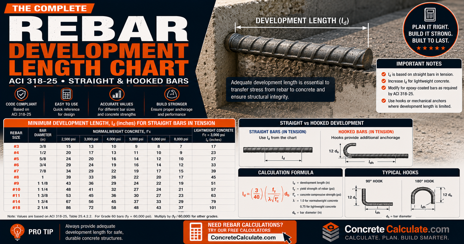
Rebar Development Length Chart (ACI 318-25)
Development length is the embedded length a reinforcing bar needs to develop its yield strength in concrete. There is no single number for a given bar size: development length depends on bar diameter, steel grade, concrete strength, casting position, coating, cover, spacing, and confinement. This chart provides ACI 318-25 reference values under clearly stated assumptions, with separate cases for straight, hooked, headed, and compression anchorage.
Every development length value below applies only to the stated bar size, steel grade, concrete strength, casting position, coating, and confinement condition. Changing any one of these variables changes the required length. Never apply a straight-bar tension value to a hooked bar, a compression bar, or a bundled bar. This chart is a reference tool. It does not replace the project structural drawings, the engineer of record’s reinforcement details, or the applicable building code edition adopted by the local jurisdiction.
On This Page
- Quick reference chart
- What is rebar development length
- Development length vs anchorage length
- Development length vs lap splice length
- Development length vs stock/cut length
- What controls development length
- ACI 318-25 straight-bar tension formula
- Development length by bar size
- Development length by concrete strength
- Development length by rebar grade
- Top-bar development length
- Epoxy-coated rebar development length
- Normalweight vs lightweight concrete
- Concrete cover and development length
- Rebar spacing and development length
- Transverse reinforcement and Ktr
- Tension vs compression development
- Compression development length chart
- Standard hook development length
- Headed rebar development length
- Straight vs hooked vs headed comparison
- Development length for bundled rebar
- Development length for post-installed rebar
- Beams, slabs, walls, columns, footings
- Development length at supports and cutoffs
- Development length in seismic applications
- Can development length be reduced
- Worked examples
- How to read this chart
- ACI 318-25 Chapter 25 requirements
- ACI 318-19 vs ACI 318-25
- Common mistakes
- Limitations
- FAQs
Rebar Development Length Chart: Quick Reference
The table below covers the single most common design case: a Grade 60, normalweight, uncoated, straight tension bar in a bottom-cast (non-top-bar) position. It assumes clear cover equal to one bar diameter and clear spacing equal to one bar diameter, with no credit taken for transverse reinforcement, which corresponds to a confinement term (cb + Ktr)/db of 1.5 under ACI 318-25 Section 25.4.2. This is a common, moderately conservative detailing condition, not the only possible case.
Baseline Tension Development Length (in inches)
| Bar Size | db (in) | 3,000 psi | 4,000 psi | 5,000 psi | 6,000 psi |
|---|---|---|---|---|---|
| #3 | 0.375 | 17 | 15 | 13 | 12 |
| #4 | 0.500 | 22 | 19 | 17 | 16 |
| #5 | 0.625 | 28 | 24 | 22 | 20 |
| #6 | 0.750 | 33 | 29 | 26 | 24 |
| #7 | 0.875 | 48 | 42 | 38 | 34 |
| #8 | 1.000 | 55 | 48 | 43 | 39 |
| #9 | 1.128 | 62 | 54 | 48 | 44 |
| #10 | 1.270 | 70 | 61 | 54 | 50 |
| #11 | 1.410 | 78 | 67 | 60 | 55 |
Note the jump between #6 and #7: ACI 318-25 applies a bar-size factor (ψs) of 0.8 to #6 and smaller bars, versus 1.0 for #7 and larger, so development length does not scale in strict proportion to diameter alone.
Development-Length Case Selector
Development length is not a single calculation. Use this table to find which ACI 318-25 provision actually applies to your bar before reading a number off any chart.
| Reinforcement Condition | Development Type | Symbol | ACI 318-25 Reference |
|---|---|---|---|
| Straight bar in tension | Straight tension development | ld | §25.4.2 |
| Standard hook in tension | Hooked development | ldh | §25.4.3 |
| Headed deformed bar | Headed-bar development | ldt | §25.4.4 |
| Straight bar in compression | Compression development | ldc | §25.4.9 |
| Post-installed bar | Special straight-bar provisions | ld | §25.4.2.6 |
| Lap splice (not a development check) | Splice length | lst / lsc | §25.5 |
What Is Rebar Development Length?
Development length is the length of reinforcing steel that must be embedded and bonded into the surrounding concrete beyond a critical section so the force assumed in structural design can actually transfer from the steel into the concrete. It is a bond and anchorage requirement, not a physical property printed on a mill certificate.
Why Development Length Is Required
Reinforced concrete relies on load transfer between two materials: steel carries tension, concrete carries compression, and the two must stay connected under load. That connection happens through bond: chemical adhesion between the bar surface and the cement paste, friction, and mechanical bearing of the bar’s deformations (ribs) against the surrounding concrete. If a bar is cut too short, it can pull out or slip before reaching its design stress, which is a bond failure rather than a ductile steel failure.
What ld Means
In ACI notation, ld is the required tension development length for a straight deformed bar. Related symbols on this page include ldh for standard hooks, ldt for headed bars, and ldc for straight compression bars. Each has its own governing equation in ACI 318-25 Chapter 25.
Development Length vs Anchorage Length
“Anchorage” is the broader engineering concept: any method of transferring force from a reinforcing bar into concrete at the end of the bar. Development length is one specific form of anchorage, the straight-bar bond mechanism. Other anchorage methods include standard hooks, headed bars, and mechanical anchors. All of them are trying to accomplish the same outcome, transferring the design force into the concrete, but the governing ACI equation and the physical geometry are different for each.
- Straight-bar bond development: force transfers through bond stress along the embedded length.
- Hook anchorage: a bend at the end of the bar adds bearing resistance to the bond mechanism.
- Headed-bar anchorage: a forged or welded head at the bar end transfers force mainly through bearing.
- Mechanical anchorage: proprietary devices, evaluated under their own qualification criteria.
- Available embedment length: the physical length actually provided in the structure, which must meet or exceed whichever development or anchorage length governs.
Development Length vs Lap Splice Length
Development length develops force from one bar into the surrounding concrete. Lap splice length transfers force between two overlapping bars through the surrounding concrete. These are related calculations, but they answer different structural questions, and ConcreteCalculate covers splice length separately in the Rebar Lap Splice Chart.
Why Lap Length Is Often Based on Development Length
ACI 318-25 defines tension lap splice length as a multiple of the straight tension development length: a Class A splice uses 1.0 × ld and a Class B splice uses 1.3 × ld, subject to the conditions in Section 25.5. Because splice length is derived from ld, changing the development length assumptions (grade, concrete strength, coating, cover) changes the splice length too.
Why ld and Lap Length Should Not Be Interchanged
A development length only has to anchor one bar into concrete. A lap splice has to transfer force between two adjacent bars competing for the same surrounding concrete, which is a less efficient bond condition. That is why lap splices are always longer than the underlying development length, never equal to or shorter than it. For splice-specific values, classes, and staggering guidance, see the Rebar Lap Splice Chart.
Development Length vs Rebar Stock/Cut Length
These three terms describe different things entirely:
- Development length: the structural anchorage requirement calculated from ACI 318-25.
- Stock length: the length reinforcing bar is purchased in, commonly 20 ft, 40 ft, or 60 ft depending on supplier and bar size.
- Cut/fabricated length: the physical dimension of a bar after it has been cut and bent for a specific placement in the structure.
A 20 ft stock bar does not have a “20 ft development length.” Development length is a required minimum embedment, and it is typically a small fraction of the total bar length. For stock sizing and fabrication reference, see the Rebar Size Chart.
What Controls Rebar Development Length?
ACI 318-25’s straight-bar tension provisions combine several interacting variables into one equation rather than assigning a single length to each bar number.
Rebar Diameter / Bar Size
Development length scales with bar diameter, db, because a larger bar carries more total force at the same yield stress and needs more surface area in contact with concrete to develop that force through bond.
Steel Yield Strength / Grade
Higher-yield reinforcement (Grade 80, Grade 100) carries a higher design force per bar, and ACI 318-25 applies a reinforcement-grade factor, ψg, that increases required development length above Grade 60 baselines.
Concrete Compressive Strength
Development length is inversely proportional to the square root of f′c. Higher-strength concrete bonds more effectively per unit length, which shortens the required embedment.
Concrete Density
Lightweight concrete has lower bond capacity than normalweight concrete of the same compressive strength, so ACI 318-25 applies a density factor, λ, that increases required length for lightweight mixes.
Casting Position
Bars cast near the top of a deep concrete placement are more likely to sit in a weaker bond zone caused by bleed water and settlement beneath them, triggering the top-bar factor, ψt.
Epoxy or Other Coating Condition
Epoxy coating reduces the mechanical bond between the bar ribs and the concrete, requiring the coating factor, ψe, which increases with tighter cover or spacing.
Concrete Cover
Cover affects the bar’s resistance to splitting the concrete around it during bond transfer, and it is a direct input to the confinement term in the general ACI equation.
Bar Spacing
Adjacent bars share the same surrounding concrete. Tighter spacing reduces the concrete available to resist splitting, which can increase required development length.
Transverse Reinforcement / Confinement
Ties, stirrups, and spirals that cross the potential splitting plane provide confinement credit, represented by Ktr, which can shorten development length when properly detailed.
Anchorage Type
Straight, hooked, headed, and post-installed bars each use a different ACI 318-25 equation, so the anchorage type itself is a controlling variable, not just a modifier.
ACI 318-25 Straight-Bar Tension Development Length
ACI 318-25 Section 25.4.2 gives the general equation for the tension development length of a straight deformed bar or deformed wire:
General Development-Length Equation (Eq. 25.4.2.4a)
ld = (3/40) × [fy / (λ√f′c)] × [(ψtψeψsψg) / ((cb + Ktr)/db)] × db, subject to a 12 in absolute minimum.
Variables:
- fy = specified yield strength of reinforcement (psi)
- f′c = specified concrete compressive strength (psi), capped in the equation at √f′c ≤ 100 psi per ACI unless higher-strength provisions are invoked
- db = nominal bar diameter (in)
- λ = lightweight concrete factor (1.0 normalweight, 0.85 sand-lightweight, 0.75 all-lightweight)
- ψt = casting-position factor (1.3 top bar, 1.0 other)
- ψe = epoxy/coating factor (1.0 uncoated, 1.2 to 1.5 epoxy-coated depending on cover/spacing)
- ψs = bar-size factor (0.8 for #6 and smaller, 1.0 for #7 and larger)
- ψg = reinforcement-grade factor (1.0 Grade 40/60, higher for Grade 80/100)
- cb = smaller of the distance from bar center to the nearest concrete surface, or half the center-to-center bar spacing (in)
- Ktr = transverse reinforcement index, credited confinement across the potential splitting plane (in)
ACI limits the confinement term (cb + Ktr)/db to a maximum of 2.5, and limits the product ψt × ψe to a maximum of 1.7, so a top bar with tight-spacing epoxy coating does not stack to an unrealistically high combined factor.
Simplified ACI Table Method
When clear spacing or cover meets specific minimums (generally clear cover ≥ db and clear spacing ≥ db, with minimum ties or stirrups, or clear spacing ≥ 2db with clear cover ≥ db), ACI 318-25 permits a simplified expression that sets (cb+Ktr)/db = 1.5 and collapses the equation to a single constant:
#7 bars and larger: ld = [fyψtψe / (20λ√f′c)] × db
#6 bars and smaller: ld = [fyψtψe / (25λ√f′c)] × db
This simplified form is what generates the Quick Reference table above and is adequate for most conventional detailing. It should not be used when cover or spacing falls below the stated minimums.
General Development-Length Equation
Where actual cover, spacing, and transverse reinforcement are known, the full equation with the explicit (cb + Ktr)/db term produces a more accurate, often shorter, result. Ktr is calculated as 40Atr/(sn), where Atr is the total cross-sectional area of transverse reinforcement crossing the splitting plane, s is the maximum spacing of that transverse reinforcement, and n is the number of bars being developed at the section.
Rebar Development Length by Bar Size
Development length increases with bar diameter, but not in exact proportion, because the bar-size factor ψs changes at the #6/#7 boundary.
#3 and #4 Rebar
These smaller bars fall in the ψs = 0.8 category. At 4,000 psi, Grade 60, uncoated, bottom-cast, baseline conditions produce approximately 15 in for #3 and 19 in for #4.
#5 and #6 Rebar
Still governed by ψs = 0.8. Under the same baseline, #5 requires approximately 24 in and #6 requires approximately 29 in.
#7 and #8 Rebar
At #7 and larger, ψs jumps to 1.0, producing a visible increase in the ld/db ratio. Under baseline conditions, #7 requires approximately 42 in and #8 requires approximately 48 in.
#9 through #11 Rebar
Development length continues to scale with diameter at ψs = 1.0. Under baseline conditions, #9 requires approximately 54 in, #10 approximately 61 in, and #11 approximately 67 in.
Larger bars generally need more development length simply because they carry more total tensile force at the same stress and have a lower surface-area-to-force ratio, but diameter alone does not control the result. Grade, concrete strength, casting position, and confinement all shift these baseline numbers.
Development Length by Concrete Strength
The table below fixes the bar sizes, Grade 60, and baseline detailing conditions while varying concrete strength.
| f′c (psi) | #4 ld | #5 ld | #6 ld | #8 ld |
|---|---|---|---|---|
| 3,000 | 22 | 28 | 33 | 55 |
| 4,000 | 19 | 24 | 29 | 48 |
| 5,000 | 17 | 22 | 26 | 43 |
| 6,000 | 16 | 20 | 24 | 39 |
| 8,000 | 14 | 17 | 21 | 34 |
| 10,000 | 12 | 15 | 18 | 30 |
Development length is inversely proportional to √f′c, so gains diminish at higher strengths. Some CRSI reference tables historically span 3,000 to 10,000 psi under the ACI 318-19 framework; the values above are calculated directly from ACI 318-25 and should not be assumed identical to older-code tables, since ACI 318-25 revised several of the modification factors feeding this calculation.
Development Length by Rebar Grade
ACI 318-25 applies a reinforcement-grade factor, ψg, that increases with higher-strength reinforcement: 1.0 for Grade 40 and Grade 60, 1.15 for Grade 80, and 1.3 for Grade 100.
| Grade | fy (psi) | #5 ld | #8 ld |
|---|---|---|---|
| Grade 40 | 40,000 | 16 | 32 |
| Grade 60 | 60,000 | 24 | 48 |
| Grade 80 | 80,000 | 37 | 73 |
| Grade 100 | 100,000 | 52 | 103 |
Grade 60 Baseline
Grade 60 is the most common reinforcement grade in U.S. general building construction and is used as the baseline case throughout this chart. See the Rebar Grade Chart for full grade and strength designations.
Grade 80 and Grade 100
Higher-strength reinforcement should never simply inherit Grade 60 development lengths scaled by yield stress alone. ACI 318-25 applies the explicit ψg factor shown above, and member-specific detailing, particularly in special seismic systems, can impose additional confinement requirements on high-strength longitudinal reinforcement beyond the basic development length calculation.
Top-Bar Development Length
Casting position affects bond quality. Horizontal reinforcement placed with a significant depth of fresh concrete beneath it can settle into a weaker bond zone as bleed water rises and aggregate settles, compared with otherwise identical bottom-cast reinforcement.
What Is a “Top Bar”?
Under ACI 318-25, a bar qualifies for the top-bar casting-position factor, ψt = 1.3, when it is horizontal reinforcement with more than 12 in of fresh concrete cast below it in the member. Bars that do not meet this condition use ψt = 1.0.
Top Bar vs Other Bar Comparison
| Casting Position | ψt | Development Length |
|---|---|---|
| Bottom bar / other position | 1.0 | 24 in |
| Top bar (>12 in fresh concrete below) | 1.3 | 31 in |
The top-bar factor alone adds roughly 30 percent to the required length in this example. Underestimating ld by ignoring casting position is one of the most common chart-reading mistakes on this topic.
Epoxy-Coated Rebar Development Length
Epoxy coating reduces the mechanical interlock between bar deformations and concrete, so ACI 318-25 requires a coating factor, ψe, that depends on how tight the surrounding cover and spacing are.
Epoxy with Tight Cover or Spacing
When clear cover is less than 3db, or clear spacing is less than 6db, ψe = 1.5.
Other Epoxy Conditions
For epoxy-coated bars outside the tight cover/spacing condition, ψe = 1.2.
Uncoated and Galvanized Bars
Uncoated and galvanized bars use ψe = 1.0.
| Coating Condition | ψe | Development Length |
|---|---|---|
| Uncoated / galvanized | 1.0 | 24 in |
| Epoxy-coated, standard cover/spacing | 1.2 | 29 in |
| Epoxy-coated, tight cover or spacing | 1.5 | 36 in |
Recall that ψt × ψe is capped at 1.7 in the ACI equation, so a top bar that is also tightly spaced epoxy-coated does not multiply both penalties in full.
Normalweight vs Lightweight Concrete
ACI 318-25 applies a concrete-density modification factor, λ, because lightweight concrete has measurably lower bond strength than normalweight concrete at the same compressive strength. λ = 1.0 for normalweight, 0.85 for sand-lightweight, and 0.75 for all-lightweight concrete (unless a project-specific splitting tensile strength test justifies an alternate value).
| Concrete Type | λ | Development Length |
|---|---|---|
| Normalweight | 1.0 | 24 in |
| Sand-lightweight | 0.85 | 28 in |
| All-lightweight | 0.75 | 32 in |
Most general building construction in the U.S. uses normalweight concrete, so lightweight adjustments matter mainly on projects specifying lightweight structural concrete for weight reduction.
Concrete Cover and Development Length
Cover is the distance from the bar surface to the nearest concrete face. It matters for development length because it governs the concrete’s resistance to splitting outward as bond stress builds along the bar, and it directly feeds the cb term in the ACI confinement equation. This section connects closely to the Concrete Cover Chart, which covers minimum cover requirements by exposure condition and member type.
Low Cover vs Greater Cover
Greater cover generally allows a larger cb value, which can shorten the calculated development length up to the ACI-imposed ceiling of (cb+Ktr)/db = 2.5. Beyond that ceiling, additional cover provides no further calculated reduction in ld, because the ACI equation caps the benefit at that ratio.
Rebar Spacing and Development Length
Adjacent bars interact through the surrounding concrete, not independently. Tighter clear or center-to-center spacing reduces the concrete area available to resist splitting between bars, which is why spacing is a direct input to the cb term. Congested reinforcement layouts, common in heavily loaded beams, columns, and transfer members, often require the general ACI equation rather than the simplified table method because minimum spacing thresholds are not met. For spacing limits and layout guidance, see the Rebar Grid Calculator.
Transverse Reinforcement and Ktr
Ties, stirrups, and other transverse reinforcement that cross a bar’s potential splitting plane provide measurable confinement, represented in the ACI equation by Ktr = 40Atr/(sn). Properly detailed transverse reinforcement increases the confinement term (cb+Ktr)/db, which can shorten the calculated development length, up to the code-imposed ceiling of 2.5. ACI 318-25 requires that transverse reinforcement credited for confinement either be properly developed across the potential splitting plane, or satisfy the applicable stirrup, tie, spiral, or hoop detailing provisions elsewhere in the code. If Ktr is unknown or conservatively taken as zero, the simplified table method or the general equation with Ktr = 0 still applies.
Tension Development Length vs Compression Development Length
Tension and compression development are governed by separate ACI 318-25 provisions and should never be read from the same table without clear labeling.
Tension ld
Tension development is controlled by bond behavior under tensile stress, where splitting cracks are a real failure concern, which is why cover, spacing, and confinement are so influential in the equation.
Compression ldc
Compression development is governed by ACI 318-25 Section 25.4.9 and uses a different, generally shorter, equation because compression bars do not rely on the same splitting-crack bond mechanism as tension bars, and the end bearing of the bar contributes to force transfer.
Why Compression Is Not Just “Use the Tension Number”
Applying a tension development length to a compression bar is conservative in some cases and can misrepresent the governing failure mode in others. ACI research has continued to examine compression development and splice behavior, which is exactly why the code maintains a distinct calculation rather than a universal rule of thumb.
Compression Development Length Chart
ACI 318-25 Section 25.4.9 gives the compression development length, ldc, as the greater of two expressions, subject to an 8 in minimum:
(a) ldc = [fyψr / (50λ√f′c)] × db
(b) ldc = 0.0003 × fy × ψr × db, not less than 8 in
ψr is a confinement-related factor; it is taken as 1.0 in the baseline table below (no reduction for spiral confinement).
| Bar Size | db (in) | 3,000 psi | 4,000 psi | 5,000 psi | 6,000 psi | Notes |
|---|---|---|---|---|---|---|
| #3 | 0.375 | 9 | 8 | 8 | 8 | 8 in minimum governs |
| #4 | 0.500 | 11 | 10 | 9 | 9 | |
| #5 | 0.625 | 14 | 12 | 12 | 12 | |
| #6 | 0.750 | 17 | 15 | 14 | 14 | |
| #7 | 0.875 | 20 | 17 | 16 | 16 | |
| #8 | 1.000 | 22 | 19 | 18 | 18 | |
| #9 | 1.128 | 25 | 22 | 21 | 21 | |
| #10 | 1.270 | 28 | 25 | 23 | 23 | |
| #11 | 1.410 | 31 | 27 | 26 | 26 |
These compression values apply only to straight bars in compression, such as column longitudinal bars or dowels checked in compression. Do not use this table for tension bars, hooks, or headed anchorage.
Equipment for Your Project
Affiliate disclosure: As an Amazon Associate, ConcreteCalculate earns from qualifying purchases. We may also earn a commission from other affiliate links at no additional cost to you.
Standard Hook Development Length
A standard hook is a distinct anchorage method, not simply a straight development length with a bend tacked on. ACI 318-25 measures ldh from the critical section to the outside edge of the hook (the point of tangency of the bend).
ACI 318-25 revised the hooked-bar development equation. ACI 318-19 had significantly increased required hook lengths compared with ACI 318-14. Structural engineering commentary on the 2025 code indicates the committee found the 318-19 increase overly conservative and not well supported by test data, so ACI 318-25 restores an equation structurally similar to ACI 318-14, while adding a new reinforcement size-effect factor. Designers should not assume older ACI 318-19 hook charts remain valid.
Standard Hook Development (ACI 318-25 §25.4.3.1)
ldh = [fyψeψrψoψc / (55λ√f′c)] × db1.5, subject to a minimum of 8db or 6 in, whichever is greater.
- ψe = coating factor (1.2 epoxy-coated, 1.0 uncoated/galvanized)
- ψr = confinement factor for 90° hooks (1.0 with ties at ≤3db spacing or side cover ≥2.5 in; 1.6 without that confinement; not applicable to 180° hooks, which use 1.0)
- ψo = location factor (1.0 for hooks anchored within a column core or enclosed joint; 1.25 elsewhere)
- ψc = concrete-strength related factor as defined in ACI 318-25 §25.4.3
| Bar Size | Without confinement (ψr=1.6) | With ties/confinement (ψr=1.0) |
|---|---|---|
| #3 | 8 | 6 |
| #4 | 13 | 8 |
| #5 | 18 | 11 |
| #6 | 23 | 15 |
| #7 | 29 | 18 |
| #8 | 35 | 22 |
| #9 | 42 | 26 |
| #10 | 50 | 31 |
| #11 | 58 | 37 |
Straight Bar vs Hooked Bar Development
For a #5 bar, Grade 60, f′c = 4,000 psi, straight tension development is approximately 24 in, while hooked development without confinement credit is approximately 18 in, and with confinement credit approximately 11 in. Hooks generally anchor a bar in a shorter projected length than a straight bar, which is exactly why they are used where straight embedment does not physically fit, such as at beam-column joints or footing edges.
Headed Rebar Development Length
A headed deformed bar has a forged or welded head at the embedded end that transfers force primarily through bearing against the concrete, supplementing the bond along the bar shank. ACI 318-25 Section 25.4.4 governs headed-bar development, ldt, measured from the critical section to the bearing face of the head.
ACI 318-25 shortened headed-bar development. The equation retains its overall structure from ACI 318-19 but the constant in the denominator was increased, reducing calculated headed-bar development length by roughly 17 percent compared with ACI 318-19 under equivalent conditions, according to structural engineering industry summaries of the 2025 code changes.
Headed-bar design also requires checking the bar and head geometry, cover, spacing, and confinement conditions specified in ACI 318-25, since ACI 318-25 introduced explicit breakout-capacity checks for reinforcing bar groups (including hooked and headed bars) in new Section 25.4.11 that did not exist in this form in ACI 318-19.
Headed Bar vs Hooked Bar
Both anchorage types can produce a shorter embedment than straight bars, and both add bearing action to the bond mechanism, but they are not interchangeable. Headed bars are compact and avoid the bend congestion of hooks, which is useful in tight reinforcement cages, but they depend on qualified head geometry and manufacturer or ACI 318-25 compliance data. Hooks depend on bend geometry and confinement instead. Neither is universally better; the appropriate choice depends on detailing constraints, congestion, and cost at each connection.
Straight vs Hooked vs Headed Rebar Development
| Anchorage Type | Symbol | Primary Force Transfer | Space Requirement | Major Governing Inputs |
|---|---|---|---|---|
| Straight | ld | Bond along embedded length | Typically the longest straight embedment | Bar size, grade, concrete strength, cover, spacing, coating |
| Hooked | ldh | Bond plus hook bearing | Requires bend geometry and tail extension | Bar size, grade, concrete strength, coating, confinement, hook location |
| Headed | ldt | Bond plus head bearing | Compact end anchorage, qualified head geometry | Head geometry, spacing, cover, concrete strength, bar group breakout checks |
Development Length for Bundled Rebar
A bundle of two, three, or four bars is not treated the same as an isolated bar of the same size. ACI 318-25, consistent with prior editions, requires the development length of each bar within a bundle to be calculated using an increased effective diameter that reflects the bundle as a group, since bundled bars share and compete for the same surrounding concrete bond zone. Individual bars within three- and four-bar bundles carry increased development length requirements compared with an isolated bar of the same nominal size, and bar terminations within a bundle should be staggered rather than cut off at the same location. Ordinary single-bar chart values on this page should not be applied directly to bundled reinforcement; the bundle-specific ACI provisions govern.
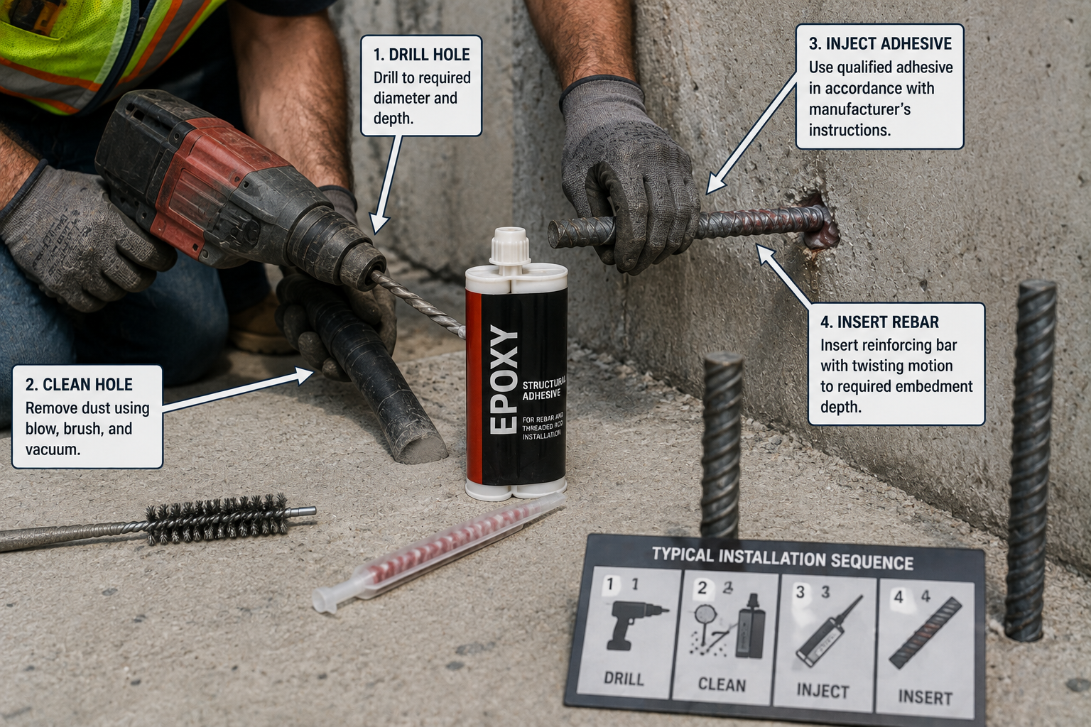
Development Length for Post-Installed Rebar
Post-installed reinforcing bars are drilled and bonded into hardened concrete with a qualified adhesive anchoring system, rather than cast in place with the original concrete pour. This is a distinct installation condition, and ACI 318-25 specifically expanded its treatment of post-installed reinforcing bars as one of the notable changes from ACI 318-19.
ACI 318-25 Section 25.4.2.6 permits specific treatment of casting-position and transverse-reinforcement terms when calculating straight-bar development for qualified post-installed reinforcing bar systems. Post-installed bars must use a qualified adhesive anchoring system with published ICC-ES or equivalent qualification data, and installation depth, hole preparation, and existing transverse reinforcement all affect the achievable development length.
Do not treat post-installed reinforcement as automatically equivalent to cast-in-place reinforcement. Product-specific qualification data, installation procedures (drilling, hole cleaning, adhesive cure time and temperature), and the applicable ACI 318-25 and manufacturer requirements must all be checked before assuming a post-installed bar meets the same development length as a cast-in-place bar of the same size.
Development Length in Beams, Slabs, Walls, Columns, and Footings
Member type does not create one fixed development length. It establishes the structural context in which the applicable ACI 318-25 provisions are checked against the available embedment in that specific member.
Beams
Beam reinforcement development is checked at critical sections such as supports, points of maximum moment, and bar cutoff locations, distinguishing top (negative-moment) bars from bottom (positive-moment) bars for casting-position purposes.
Slabs and Walls
Distributed reinforcement in slabs and walls is typically lighter and more closely spaced, and development is checked where bars terminate or where reinforcement ratio changes.
Columns
Column longitudinal reinforcement and dowels are frequently checked in compression using ldc, though tension checks apply where uplift, flexure, or splice conditions govern.
Footings and Foundations
Reinforcement anchoring into a footing from a supported column or wall, and footing reinforcement itself, must satisfy development length measured from the appropriate critical section within the footing.
Development Length at Supports and Bar Cutoffs
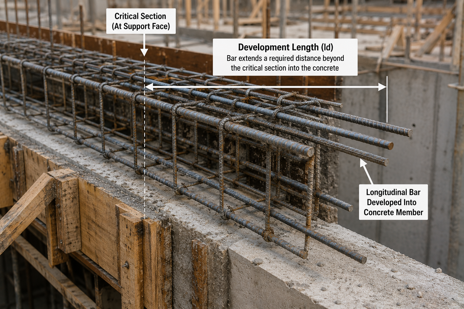
Bar cutoff and termination locations are governed by a simple but essential relationship:
Available development length ≥ Required development length, checked at the applicable critical section, subject to all other ACI 318-25 member-specific provisions.
Relevant concepts include the critical section (the point where the bar is assumed to require full development), the available embedment (the physical length remaining from that section to the bar’s actual termination or a point where it becomes fully stressed), positive and negative moment reinforcement requirements at supports, and points of inflection where moment reinforcement requirements change. These checks are separate from, and in addition to, the basic ld calculation itself.
Development Length in Seismic Applications
Seismic anchorage requirements can differ materially from ordinary gravity-system development length and should not be read off the quick-reference chart at the top of this page. Special moment frame beam-column joints, in particular, carry additional detailing requirements for hooks, heads, and confinement geometry. ACI 318-25 contains expanded and clarified seismic provisions, and some seismic anchorage requirements are based on developing a bar stress greater than the ordinary specified yield strength, fy, to account for the higher stresses reinforcement can experience under seismic loading. Seismic detailing should always be verified against the project’s applicable seismic design category and the engineer of record’s details, not against a generic reference chart.
Can Development Length Be Reduced?
Development length can be reduced only through code-recognized mechanisms, and only within the limits ACI 318-25 actually permits.
- Excess reinforcement area at a section, where ACI specifically permits a reduction based on the ratio of required to provided reinforcement area.
- Improved confinement from properly detailed transverse reinforcement, up to the (cb+Ktr)/db ceiling of 2.5.
- Favorable cover and spacing conditions that increase cb, again subject to the same ceiling.
- Switching to a hook, head, or qualified mechanical anchorage where geometry allows a shorter anchorage type.
Reductions are restricted or unavailable in several common situations, including many seismic special moment frame details, top-bar conditions (which cannot be reduced away, only compensated for with more embedment or a different anchorage type), and situations where a reduction provision’s specific conditions are not actually met. Do not shorten a bar simply because “extra steel was installed elsewhere” without confirming the specific ACI 318-25 provision that permits the reduction at that particular section.
Rebar Development Length Worked Examples
Example 1: #5 Grade 60 Straight Bottom Bar
Given: #5 bar (db = 0.625 in), fy = 60,000 psi, f′c = 4,000 psi normalweight concrete, uncoated, bottom bar, baseline cover/spacing ((cb+Ktr)/db = 1.5).
Step 1: Use the simplified equation for #6 and smaller: ld = [fyψtψe / (25λ√f′c)] × db.
Step 2: ld = [60,000 × 1.0 × 1.0 / (25 × 1.0 × 63.25)] × 0.625 = [60,000 / 1,581] × 0.625 ≈ 23.7 in.
Practical interpretation: This bar must extend at least 24 in past the critical section to develop full yield strength under these specific conditions.
Example 2: Same Bar as a Top Bar
Given: Same as Example 1, except the bar now has more than 12 in of fresh concrete cast below it (ψt = 1.3).
Step 1: ld = [60,000 × 1.3 × 1.0 / (25 × 1.0 × 63.25)] × 0.625 ≈ 30.8 in.
What it means: Casting position alone adds roughly 7 in, about 30 percent, to this bar’s required development length.
Example 3: Epoxy-Coated #5 Bar
Given: Same as Example 1, bottom bar, but epoxy-coated with clear cover less than 3db (ψe = 1.5).
Step 1: ld = [60,000 × 1.0 × 1.5 / (25 × 1.0 × 63.25)] × 0.625 ≈ 35.6 in.
What it means: Epoxy coating with tight cover adds about 12 in compared with the uncoated baseline in this example.
Example 4: Grade 60 vs Grade 80
Given: #8 bar (db = 1.0 in), f′c = 4,000 psi normalweight, uncoated, bottom bar, baseline cover/spacing.
Step 1 (Grade 60): ψg = 1.0. ld = [60,000 × 1.0 / (20 × 63.25)] × 1.0 ≈ 47.4 in → 48 in.
Step 2 (Grade 80): ψg = 1.15, and fy = 80,000. ld = [80,000 × 1.15 / (20 × 63.25)] × 1.0 ≈ 72.7 in → 73 in.
What it means: Grade 80 does not simply require 33 percent more length in proportion to yield stress; the ψg factor adds an additional penalty on top of the higher fy.
Example 5: Straight vs Standard Hook
Given: #5 bar, Grade 60, f′c = 4,000 psi, normalweight, uncoated, anchored outside a joint core with no tie confinement credit (ψr = 1.6, ψo = 1.25).
Straight: ld ≈ 24 in (from Example 1).
Hooked: ldh = [60,000 × 1.0 × 1.6 × 1.25 × 1.0 / (55 × 1.0 × 63.25)] × 0.6251.5 ≈ 17.8 in → 18 in, subject to a minimum of 8db = 5 in or 6 in.
What it means: The hook anchors this bar in a shorter projected length, which is why hooks are used where straight embedment does not fit.
How to Read a Rebar Development Length Chart
Work through these checks in order before applying any number from a chart or calculator:
- Determine whether the bar is in tension or compression.
- Identify whether the anchorage is straight, hooked, headed, or post-installed.
- Determine the bar size and its nominal diameter, db.
- Determine the specified yield strength, fy, and reinforcement grade.
- Determine the specified concrete compressive strength, f′c.
- Identify whether the concrete is normalweight or lightweight.
- Determine the casting position (top bar or other).
- Identify the bar’s coating condition (uncoated, epoxy, galvanized).
- Check the actual clear cover and clear spacing at the section.
- Check for credited transverse confinement (ties, stirrups, spirals).
- Calculate the required development length using the applicable ACI 318-25 equation.
- Compare the required length with the available anchorage in the actual structure.
- Check any member-specific or seismic provisions that may add requirements.
- Verify the result against the project’s structural drawings and the governing code edition.
ACI 318-25 Development-Length Requirements
ACI CODE-318-25, Building Code Requirements for Structural Concrete, was published in 2025 and is the current structural concrete code referenced by this page. Development and anchorage of reinforcement is governed by Chapter 25, Section 25.4.
ACI 318-25 Chapter 25
Chapter 25 covers reinforcement details generally, with Section 25.4 specifically addressing development and anchorage of reinforcement.
Straight Bars: Section 25.4.2
Governs the tension development length of straight deformed bars and deformed wire, including the simplified table method and the general equation with the confinement term.
Standard Hooks: Section 25.4.3
Governs standard hook development length, ldh, with the revised equation and modification factors described earlier on this page.
Headed Bars: Section 25.4.4
Governs headed deformed bar development length, ldt, including the shortened denominator constant introduced in ACI 318-25.
Compression Development
Governed by Section 25.4.9, using the separate compression equation described in the Compression Development Length Chart section above.
Splices: Section 25.5
Governs lap splice length for both tension and compression, generally expressed as a multiple of the corresponding development length. See the Rebar Lap Splice Chart for splice-specific values and classes.
Bundled Reinforcement: Section 25.6
Governs the increased effective-diameter treatment and staggering requirements for bars grouped in two-, three-, and four-bar bundles.
ACI 318-19 vs ACI 318-25 Development Length
Many development-length references and charts still in circulation online are calibrated to ACI 318-19, including widely used industry anchorage and splice reference manuals. Since the current structural concrete code is ACI 318-25, those older charts should not be treated as current.
| Provision | ACI 318-19 | ACI 318-25 |
|---|---|---|
| Hooked-bar development, ldh | Significantly increased vs ACI 318-14 | Restores an ACI 318-14-like equation, adds a new bar-size effect factor |
| Headed-bar development, ldt | 2019 equation structure | Same structure, denominator constant increased, roughly 17% shorter under equivalent conditions |
| Post-installed reinforcing bars | Limited explicit treatment | Expanded provisions, including §25.4.2.6 |
| Reinforcing bar group breakout | Required by reference to Chapter 17, no explicit equations | New explicit equations in §25.4.11 |
This page’s values and equations are calculated directly from the ACI 318-25 provisions described above. If a chart or calculator elsewhere gives a materially different hooked-bar or headed-bar result, check which code edition it references before assuming an error.
Common Rebar Development Length Mistakes
- Assuming every bar of a given number has the same development length regardless of grade, concrete strength, or detailing.
- Using a universal “40db” rule for every condition instead of calculating the applicable case.
- Confusing development length with lap splice length.
- Confusing development length with purchased stock or fabricated bar length.
- Ignoring steel grade when reading a chart built for a different grade.
- Ignoring concrete strength differences between the chart and the actual mix design.
- Ignoring top-bar casting position.
- Ignoring epoxy coating requirements.
- Ignoring lightweight concrete density effects.
- Ignoring actual cover conditions at the section.
- Ignoring actual clear spacing at the section.
- Ignoring available transverse reinforcement confinement credit.
- Applying straight-bar ld values to hooked-bar details.
- Applying hooked-bar values to headed-bar details.
- Using tension development length for a compression bar without checking Section 25.4.9.
- Applying ordinary single-bar values to bundled reinforcement.
- Applying cast-in-place values to post-installed reinforcement without checking qualification requirements.
- Using an ACI 318-19 chart as if it were current ACI 318-25.
- Using a gravity-system chart for seismic anchorage design.
- Measuring available embedment from the wrong critical section.
- Changing bar termination or cutoff locations without structural review.
Rebar Development Length Chart Limitations
- Development length is a structural design requirement, not a fixed dimensional property of a rebar size.
- No single ld value exists for a given bar number; every value on this page depends on the stated assumptions.
- Tension and compression development use different ACI provisions and different formulas.
- Straight, hooked, and headed bars use different anchorage provisions and are not interchangeable.
- Higher-strength reinforcement (Grade 80, Grade 100) requires the current-code grade factor, not a linear scale-up from Grade 60.
- Actual cover, spacing, and confinement at a given section can materially change the result versus the baseline conditions used here.
- Seismic members can carry additional anchorage requirements beyond ordinary gravity-system development length.
- Bundled bars require the specific bundle provisions in ACI 318-25 Section 25.6, not single-bar values.
- Post-installed reinforcement requires product qualification data and specialized provisions.
- The applicable building code edition and any jurisdictional amendments must be verified for each project.
- Construction drawings and the licensed design professional’s reinforcement details govern the actual project.
- This chart is a reference tool and does not substitute for structural design or engineering review.
Rebar Development Length FAQs
What is rebar development length?
Development length is the minimum embedded length a reinforcing bar needs beyond a critical section so bond stress can transfer the bar’s full design force into the surrounding concrete, as defined in ACI 318-25 Chapter 25.
How is development length calculated?
For straight tension bars, ACI 318-25 Section 25.4.2 gives a general equation based on yield strength, concrete strength, bar diameter, casting position, coating, bar size, reinforcement grade, and a confinement term based on cover, spacing, and transverse reinforcement. Hooked, headed, and compression bars use separate equations.
What is the development length of #4 rebar?
Under Grade 60, normalweight, uncoated, bottom-bar baseline conditions with typical cover and spacing, a #4 bar requires approximately 19 in at 4,000 psi concrete. This value changes with grade, concrete strength, casting position, coating, cover, and spacing.
What is the development length of #5 rebar?
Under the same baseline conditions, a #5 bar requires approximately 24 in at 4,000 psi concrete. See the Quick Reference chart above for other concrete strengths.
What is the development length of #6 rebar?
Under the same baseline conditions, a #6 bar requires approximately 29 in at 4,000 psi concrete.
What is the development length of #8 rebar?
Under the same baseline conditions, a #8 bar requires approximately 48 in at 4,000 psi concrete. Note that #7 and larger bars use a different bar-size factor than #6 and smaller, which is why the ratio to bar diameter increases at #7.
Is development length 40 times bar diameter?
The “40db” figure is a rough rule of thumb that happens to land close to some Grade 60, moderate-strength-concrete, baseline cases, such as roughly 38 to 48 diameters in the tables above. It is not a code requirement and should not be used in place of the actual ACI 318-25 calculation, since grade, concrete strength, coating, casting position, cover, and spacing can all move the real ratio well outside that range.
Does larger rebar need more development length?
Generally yes, because development length scales with bar diameter, but the relationship is not perfectly linear. ACI 318-25 applies a bar-size factor that changes at the #6/#7 boundary, so the length-to-diameter ratio is not constant across all bar sizes.
Does higher concrete strength reduce development length?
Yes. Development length is inversely proportional to the square root of the concrete compressive strength, so higher-strength concrete reduces the required length, though with diminishing returns at very high strengths.
Does Grade 80 require more development length than Grade 60?
Yes. ACI 318-25 applies a reinforcement-grade factor of 1.15 for Grade 80 versus 1.0 for Grade 60, in addition to the higher yield strength itself, so Grade 80 development length is more than proportionally longer than Grade 60 for the same bar size and concrete strength.
Why do top bars need different development length?
Horizontal bars cast with more than 12 in of fresh concrete beneath them can settle into a weaker bond zone as bleed water rises and aggregate settles, so ACI 318-25 applies a top-bar casting-position factor of 1.3 to account for this reduced bond quality.
Does epoxy-coated rebar need more development length?
Yes. Epoxy coating reduces the mechanical bond between the bar and the concrete, so ACI 318-25 applies a coating factor of 1.2 to 1.5 depending on cover and spacing conditions, compared with 1.0 for uncoated bars.
How does concrete cover affect development length?
Greater cover generally increases the confinement term in the ACI equation, which can shorten required development length, up to a code-imposed ceiling. Cover below the minimum assumed in a simplified chart requires the general equation with actual cover values.
Is lap splice length the same as development length?
No. Development length anchors one bar into the surrounding concrete. Lap splice length transfers force between two overlapping bars and is calculated as a multiple of the development length, typically 1.0 to 1.3 times ld depending on splice class. See the Rebar Lap Splice Chart for details.
Is hook length the same as development length?
A standard hook’s development length, ldh, is a distinct anchorage calculation from straight-bar development length, ld. Hooks typically anchor a bar in a shorter projected length but require specific bend geometry and confinement.
What is compression development length?
Compression development length, ldc, is the required embedment for a straight bar in compression, governed by ACI 318-25 Section 25.4.9. It uses a different, generally shorter equation than tension development because the failure mechanism and bearing behavior differ.
How is development length measured from a critical section?
A critical section is the point where the bar is assumed to require its full design stress, such as a point of maximum moment or a support. Available development length is measured from that critical section to the point where the bar terminates or becomes fully stressed, and it must meet or exceed the required development length.
Can a coupler replace development length?
Qualified mechanical couplers can be used to connect bars in place of a lap splice, subject to the coupler’s own ACI 318-25 qualification and classification requirements. A coupler is a splice-related connection method and is evaluated separately from the basic development length calculation of an individual bar.
Does post-installed rebar use the same development length as cast-in-place rebar?
Not automatically. Post-installed reinforcing bars require a qualified adhesive anchoring system and specific installation procedures, and ACI 318-25 Section 25.4.2.6 provides specific treatment for these conditions. Product qualification data and manufacturer installation requirements must be checked alongside the ACI provisions.
Which ACI section covers rebar development length?
ACI 318-25 Chapter 25, Section 25.4, covers development and anchorage of reinforcement, with straight bars in Section 25.4.2, standard hooks in Section 25.4.3, headed bars in Section 25.4.4, and compression development in Section 25.4.9.
Related Calculators and Charts
This chart is a technical reference based on ACI CODE-318-25, Building Code Requirements for Structural Concrete. It is intended to support understanding of development length concepts and typical baseline values, and does not replace project-specific structural design, the engineer of record’s reinforcement details, or the building code edition and amendments adopted by the local jurisdiction.