Light Pole Base Depth Chart 2026 – Foundation Depth, Diameter & Design Factors
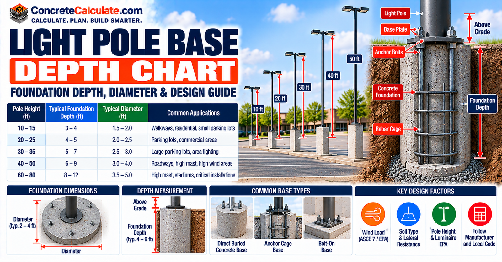
Light Pole Base Depth Chart
Foundation Depth, Diameter & Design Factors
Verified U.S. agency examples, what actually controls foundation depth, soil and wind inputs, terminology, and a concrete volume formula. There is no depth that can be set from pole height alone.
 Reviewed by Muhammad Ramzan Babar, PhD Researcher (Plasma Physics) & Calculator Developer, View Profile
⭐ Light Pole Base Depth Chart: U.S. Planning and Agency Examples
Documented examples from named engineered systems, with the pole, wind and soil context each one depends on.
How to Use the Chart
Read each row as a statement about one engineered system, not as a requirement for every pole of that height. The same mounting height gives different depths at different design wind speeds, which is the main lesson of the FDOT rows. For general foundation depth concepts, see the foundation depth chart.
| Pole / System | Pole or Mounting Height | Foundation Depth | Source / Context | Use |
|---|---|---|---|---|
| MnDOT standard roadway pole | 40 ft (pole height) | 6 to 9 ft (standard range, varies with pole height) | Minnesota DOT lighting facts | Agency-specific reference |
| MnDOT standard roadway pole | 49 ft (pole height) | 6 to 9 ft (standard range, varies with pole height) | Minnesota DOT lighting facts | Agency-specific reference |
| MnDOT high-mast tower | 100, 120 or 140 ft | Soil-dependent; typically 3 piles at least 20 ft deep | Minnesota DOT lighting facts | High-mast example |
| FDOT aluminum pole, top-mount luminaire, 110 mph | 40 ft (design mounting height) | 6 ft | Historical FDOT engineered standard (see note) | Example only |
| Same FDOT system, 110 mph | 50 ft | 7 ft | Historical FDOT engineered standard | Example only |
| Same FDOT system, 130 mph | 40 ft | 6 ft | Historical FDOT engineered standard | Example only |
| Same FDOT system, 130 mph | 50 ft | 7 ft | Historical FDOT engineered standard | Example only |
| Same FDOT system, 150 mph | 40 ft | 7 ft | Historical FDOT engineered standard | Example only |
| Same FDOT system, 150 mph | 50 ft | 8 ft | Historical FDOT engineered standard | Example only |
Examples Are Not Universal Requirements
These values are examples from specific engineered agency systems, not universal foundation requirements. Do not select a light-pole foundation from pole height alone. Final diameter, depth, reinforcement and anchorage must satisfy the applicable pole reactions, wind and environmental loads, soil conditions, local requirements and engineered foundation design.
MnDOT: standard pole heights are 40 and 49 ft, concrete foundations are a minimum of 6 to 9 ft deep depending on pole height (with an option of a steel screw-in foundation), and high-mast towers use typically 3 piles no less than 20 ft deep, varying with soil. FDOT rows: FDOT Design Standard Index 17515 (2014 sheet): 2 ft 6 in. diameter shaft, assumed fine sand (30°), luminaire EPA 1.55 sq ft and 75 lb max. This is a historical sheet, not current FDOT criteria. FDOT depths are for grades flatter than 1:4, and use the sheet’s own definition of “total depth.” For current Florida work use the current FDOT Standard Plans.
✓ Values checked against MnDOT and FDOT Index 17515, October 2026How Deep Should a Light Pole Base Be?
The short answer is that no depth can be set from pole height alone.
There is no nationwide light-pole foundation depth based only on pole height. Required depth depends on wind loading, pole and luminaire projected area, mast-arm geometry, foundation diameter, soil lateral resistance, slope and the applicable engineered pole and foundation system. A chart like “20 ft = 4 ft, 30 ft = 5 ft, 40 ft = 6 ft” is not a code requirement unless each value belongs to an identified engineered system.
| Known Information | Enough to Choose Foundation Depth? |
|---|---|
| Pole height only | No |
| Pole height + pole diameter | No |
| Pole height + luminaire weight | No |
| Pole height + wind speed | No |
| Pole + fixture EPA + arm geometry + wind | Still missing soil and foundation conditions |
| Above + soil parameters + foundation geometry + reactions | Suitable basis for engineering design |
| Manufacturer or DOT engineered foundation for the exact stated conditions | Use only within the stated applicability |
For general foundation depth planning, see the foundation depth chart and the foundation depth calculator. Neither replaces engineered pole foundation design.
What Determines Light Pole Foundation Depth?
Many inputs, and pole height is only one of them.
| Variable | Why It Matters | Typical Effect |
|---|---|---|
| Pole height | Raises wind force and lever arm | Greater overturning demand |
| Pole projected area | Adds wind force | Greater lateral load |
| Luminaire EPA | Adds wind load near the pole top | Greater overturning moment |
| Number of luminaires | Adds area and weight | Higher demand |
| Mast-arm length | Moves loads away from the pole centerline | Can increase moment and torsion |
| Design wind speed | Strongly changes wind pressure | Higher wind generally increases demand |
| Exposure and site | Changes wind loading | Can increase design force |
| Foundation diameter | Changes soil contact and resistance | Larger diameter can increase resistance |
| Foundation depth | Mobilizes more lateral soil resistance | Greater resistance |
| Soil type | Controls lateral and vertical resistance | Weak soil can require a larger or deeper base |
| Ground slope | Reduces effective surrounding soil resistance | May require a deeper foundation |
| Groundwater | Can affect soil behavior and construction | Site-specific |
| Frost depth | Local durability and movement issue | May set minimum embedment constraints |
| Breakaway system | Alters roadside safety and base details | System-specific |
| Anchor base vs. direct burial | Changes load transfer | Different foundation approach |
Other inputs include pole shape, material and weight, atmospheric ice where applicable, wind direction, concrete properties, reinforcement, anchor-bolt arrangement and local DOT or municipal standards. The final design belongs to the structural engineer or the pole manufacturer’s engineered foundation.
Pole Height vs. Foundation Depth
Related, but not a direct mapping.
Taller poles generally add wind force and a longer lever arm, so foundation demand tends to rise with height. But two 30 ft poles can differ widely: a single compact LED fixture on a sheltered site with competent soil is a very different case from two luminaires on long mast arms on a high-wind site with weak soil. Same height, different foundation.
- H: pole height; D: foundation diameter
- A conceptual relationship, not a design equation
Light Pole Base Depth by Pole Height
Explanations for common searches, with no prescribed depths.
20-Foot Pole
No universal depth exists for a 20 ft pole. Depth depends on the pole’s wind area, the luminaire and arm, the foundation diameter and the soil. If you see a depth quoted for a 20 ft pole, check that it names the exact manufacturer or agency system and its wind and soil conditions.
25-Foot Pole
The same applies at 25 ft. Do not use a rule-of-thumb depth from the internet. Use the pole manufacturer’s engineered foundation for the exact pole, luminaire and wind speed, or have a foundation designed.
30-Foot Pole
Parking-lot and area-light poles are often around this height, and manufacturers typically provide foundation details tied to a stated wind speed, EPA and soil assumption. Do not prescribe one depth for all 30 ft poles; they range from light single-fixture poles to heavily loaded multi-fixture poles.
40-Foot Pole
MnDOT’s standard roadway poles include 40 ft, with standard concrete foundations 6 to 9 ft deep depending on pole height. In the historical FDOT top-mount standard, a 40 ft mounting height used 6 ft at 110 and 130 mph and 7 ft at 150 mph. These are system-specific examples, not universal requirements.
50-Foot Pole
In the historical FDOT top-mount standard, a 50 ft mounting height used 7 ft at 110 and 130 mph and 8 ft at 150 mph, specific to that standard. The progression with wind speed at a fixed mounting height shows why a single depth per height cannot be correct.
High-Mast Light Pole Foundation Depth
A different class of structure.
MnDOT’s high-mast towers are 100, 120 and 140 ft tall. Their foundation depth varies with soil conditions, but they typically use three piles no less than 20 ft deep. High-mast systems involve materially different loads and foundations from conventional poles, so do not extrapolate ordinary pole foundations to them.
Light Pole Foundation Diameter
Depth and diameter work together.
A narrow foundation may need a different depth than a wider one under the same overturning demand, because diameter changes the soil contact that resists lateral load. No universal diameter by pole height exists, and a deeper foundation does not automatically make up for too small a diameter. For reference, the historical FDOT standard drew its aluminum-pole foundation as a 2 ft 6 in. diameter shaft, but that is one system’s detail, not a rule.
- d: embedment depth; M: grade-level moment; P: lateral force; D: foundation diameter
Wind Speed and Foundation Depth
Higher design wind speed generally raises demand.
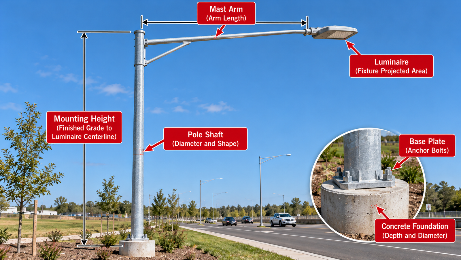
ASCE/SEI 7-22 is the nationally adopted loading standard covering wind and other environmental loads, and U.S. building-code practice incorporates it. Transportation agencies also use their own wind provisions for poles. Wind acts on the pole shaft, luminaire, mast arm and accessories. The historical FDOT standard shows the effect directly: at the same mounting height, the foundation gets deeper as the design wind speed rises.
| Design Mounting Height | 110 mph | 130 mph | 150 mph |
|---|---|---|---|
| 40 ft | 6 ft | 6 ft | 7 ft |
| 50 ft | 7 ft | 7 ft | 8 ft |
A simplified force relationship is F = qA, where q is design pressure and A is projected area. That is conceptual only: actual ASCE and AASHTO pole design uses applicable coefficients and provisions, so F = qA is not a substitute for wind design. For general wind load background, see the wind load calculator.
Luminaire EPA and Wind Load
Effective projected area is how pole manufacturers rate fixtures.
- Ap: projected area; Cf: force-related factor used by the applicable system
Two luminaires of similar weight can impose different wind loads if their projected areas or shapes differ, so luminaire weight alone does not determine wind demand. Quantity matters too: each added fixture adds area and weight. The historical FDOT standard, for instance, states that its tables assume a luminaire with an EPA of 1.55 sq ft (including drag) and a maximum weight of 75 lb. Swapping in a larger fixture or adding one invalidates those assumptions.
Mast Arm Length and Foundation Demand
Arms move the load away from the pole.
A 4 ft arm, an 8 ft arm and a 15 ft arm cannot automatically share the same foundation demand. Longer arms move luminaire weight and wind area away from the pole centerline and can add moment and torsion. Engineered standards organize their pole designs accordingly: FDOT’s aluminum standard lists pole designs by fixture arm length (8, 10, 12 and 15 ft), along with wind speed and mounting height.
Light Pole Overturning Moment
Wind force times height gives the moment the foundation must resist.
- F: lateral wind force; h: vertical lever arm from grade to the point of application
- Simplified mechanics, not a foundation design equation
Illustrative Moment at 30 ft and 40 ft
Soil Type and Foundation Depth
The same pole and load can need a different foundation in different soil.
Lateral soil resistance varies greatly by soil class, and it increases with depth. IBC Table 1806.2 gives presumptive lateral bearing values that range from 100 psf per foot of depth for clay and silt classes to 1,200 psf per foot for crystalline bedrock. Those are code presumptive values, not measured geotechnical properties. Soil is only one of several inputs; for broader soil background see the soil bearing capacity chart and the soil bearing capacity calculator.
IBC Lateral Soil-Bearing Values
Presumptive code values by material class, in psf per foot of depth below natural grade.
| Soil / Material Class | USCS Examples | Lateral Bearing Pressure (psf/ft) | Foundation Implication |
|---|---|---|---|
| Crystalline bedrock | Rock | 1,200 | Highest lateral resistance; drilling and anchorage differ in rock |
| Sedimentary and foliated rock | Rock | 400 | Much higher than soil but well below crystalline rock |
| Sandy gravel and gravel | GW, GP | 200 | Good lateral resistance for soil |
| Sand, silty sand, clayey sand, silty gravel, clayey gravel | SW, SP, SM, SC, GM, GC | 150 | Moderate resistance; groundwater can matter |
| Clay, sandy clay, silty clay, clayey silt, silt, sandy silt | CL, ML, MH, CH | 100 | Lowest presumptive lateral value; weak soil can need a larger or deeper base |
Presumptive Values, Not a Substitute for Investigation
These are IBC presumptive design values subject to Chapter 18 applicability and limitations. They are not substitutes for a geotechnical investigation where site conditions, project requirements or the building official require one. The values are not to be exceeded unless substantiating data are submitted and approved, and questionable soil classification or strength calls for further investigation.
IBC Embedded Pole Foundation Design
What Section 1807.3 covers, without reducing it to a calculator.
IBC Section 1807.3 applies to posts or poles embedded directly in earth or in concrete footings in earth, where they resist axial and lateral loads. For a nonconstrained embedded pole or footing, the code’s procedure uses these variables:
- P: applied lateral force
- h: height from grade to the point where the lateral force acts
- b: diameter of the round post or footing (or the diagonal of a square footing)
- d: depth of embedment, limited to 12 ft for this calculation
- S1: allowable lateral soil-bearing pressure, taken from the Table 1806.2 lateral value at one-third of the embedment depth
This page explains the variables and the concept only. It does not reproduce the code equation as a universal light-pole calculator. Use the adopted code edition and a design professional.
Ground Slope and Foundation Depth
Site geometry can add depth.
Sloping ground reduces the soil surrounding the foundation, which can require a deeper shaft. The historical FDOT standard gives a clear numerical example: its listed depths apply to grades flatter than 1:4, and for grades up to 1:2 the designer adds 2 ft 6 in. to the table depth.
FDOT Slope Adjustment Example
Frost Depth and Light Pole Foundations
A local issue, kept local.
Local frost conditions can affect foundation requirements, and local building codes or agency details may set frost-related minimums. Frost depth varies geographically, so no generic U.S. frost depth can be given. Structural lateral-resistance depth and frost-related embedment are separate design considerations. Do not assume a rule such as “all light-pole bases must be 12 in. below the frost line” unless an applicable local standard says so. For geographic frost information, see the frost depth chart.
Anchor-Base Light Pole Foundations
Pole, base plate, anchor rods, reinforced concrete and soil.
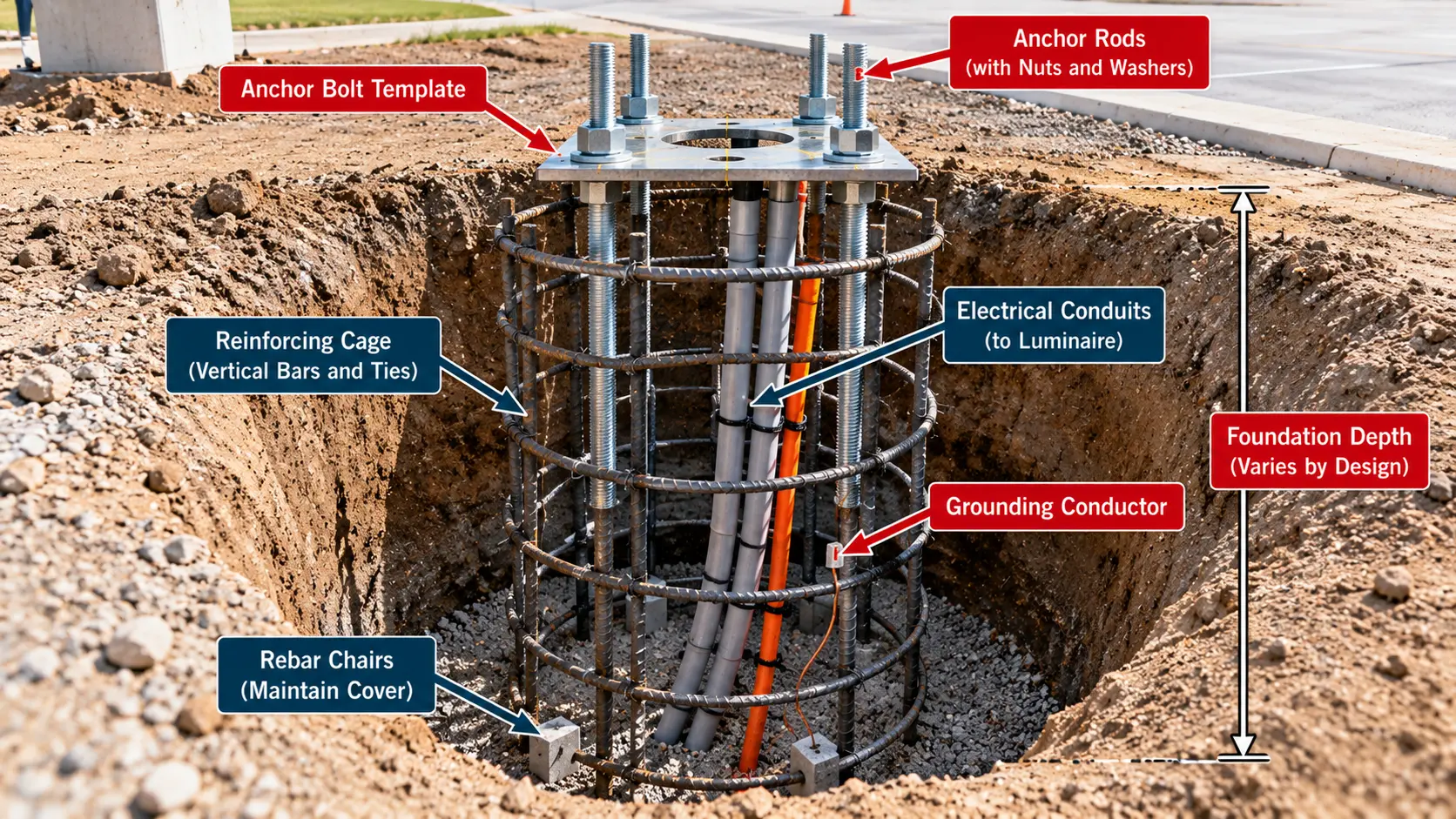
The common configuration is: pole, then base plate, then anchor rods or bolts, then a reinforced concrete foundation, then the surrounding soil. Foundation depth is not the same as anchor-bolt embedment: a 7 ft deep concrete foundation does not mean the anchor bolts are 7 ft long. DOT construction practice typically checks foundation size and depth, reinforcing placement and clearance, and correct anchor-bolt size and pattern. For hardware sizing, see the anchor bolt size chart.
Direct-Burial Light Poles
Keep this separate from anchor-base foundations.
A direct-embedded pole transfers load to the soil differently from an anchor-base pole. Do not combine direct pole embedment, concrete drilled-shaft depth and anchor-bolt embedment into one column called “base depth.” Crash-tested direct-embedded lighting assemblies also have a defined embedment configuration for that specific tested system, which is not a rule for poles in general.
Breakaway Light Pole Bases
A roadside safety topic, not a parking-lot default.
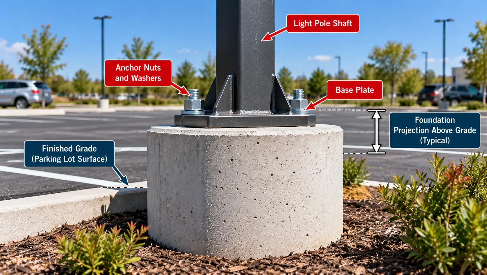
Roadside poles may need breakaway systems depending on clear-zone conditions and shielding. MnDOT notes that objects within a clear zone need either guardrail protection or a breakaway configuration, unless they are outside the clear zone. Breakaway hardware includes transformer bases, slip bases and breakaway couplings, and foundation projection above grade is part of the detail. Do not convert roadway breakaway requirements into ordinary parking-lot pole requirements. The historical FDOT sheet, for example, shows a frangible or breakaway transformer base as an option for its roadway poles.
Light Pole Anchor Bolt Embedment
A different dimension from foundation depth.
Anchor-bolt embedment is the length of bolt in concrete; foundation depth is the depth of the concrete shaft. This page gives no generic anchor-bolt length, because it comes from the engineered pole and base system and its anchor template. For general anchor-bolt calculations, see the anchor bolt embedment calculator.
Light Pole Foundation Reinforcement
No universal cage exists.
Typical elements are longitudinal bars, ties or spirals, concrete cover and an anchor cage, but their sizes and layout come from the project drawings and the pole manufacturer or agency standard. As one dated example, the historical FDOT standard shows eight longitudinal bars with ties at 12 in. maximum spacing and 3 in. cover for its 2 ft 6 in. shaft. That is one system’s detail and must not be copied as a universal cage. See the rebar size chart and rebar spacing chart for bar basics, rebar development length for anchorage, and minimum concrete cover for cover.
Concrete Strength for Light Pole Bases
Specified by the design, not assumed.
Required compressive strength comes from the project drawings, agency standards, the structural design or precast specifications. Do not assume all light-pole bases use one strength such as 3,000 psi. The historical FDOT sheet, for instance, simply calls for its Class I concrete, defined elsewhere in that agency’s specifications.
How Much Concrete Does a Light Pole Base Need?
A geometric volume for a cylindrical shaft.
- D: shaft diameter (ft); h: concrete shaft length (ft)
- With projection: h = hb (below grade) + ha (above grade)
Illustrative 24 in. by 6 ft Cylinder
| Shaft Length h | Volume (ft³) | Volume (yd³) |
|---|---|---|
| 6 ft | 29.45 | 1.09 |
| 7 ft | 34.36 | 1.27 |
| 8 ft | 39.27 | 1.45 |
| 9.5 ft | 46.63 | 1.73 |
The table uses the 2 ft 6 in. diameter shown in the historical FDOT sheet only as a convenient geometric size. Depths of 6, 7, 8 and 9.5 ft are the FDOT table values and the slope-adjusted example. Volumes are geometric estimates before any waste or project allowance. For ordering, use the concrete calculator, the concrete sonotube calculator for round forms, or the concrete footing calculator.
Foundation Depth vs. Total Length vs. Projection
Online discussions mix these up constantly.
| Term | Meaning |
|---|---|
| Pole mounting height | Height associated with luminaire mounting, defined by the applicable system |
| Pole height | Physical pole dimension; may not equal mounting height |
| Foundation diameter | Outside diameter of the concrete shaft |
| Total foundation length | Entire concrete shaft or pier length |
| Buried depth | Portion below finished grade |
| Foundation projection | Portion above finished grade |
| Anchor-bolt embedment | Length of anchor bolt embedded in concrete |
| Direct pole embedment | Length of pole or ground sleeve embedded below grade |
| Frost depth | Local depth associated with frost conditions |
A drawing may use total foundation length, buried depth and projection above grade; they are not interchangeable. With projection, the total length equals the buried depth plus the projection, so a 6 ft buried shaft that projects 1 ft above grade has a 7 ft total length. This matters when reading DOT details, where a table heading such as “total depth” must be read against the detail.
Light Pole Base Installation
A general sequence; the drawings govern.
- Verify utilities and confirm the foundation location.
- Confirm geotechnical and site assumptions against the design.
- Excavate or drill the shaft.
- Place the reinforcing cage.
- Set the anchor-bolt template at the specified circle and orientation.
- Install conduits and grounding.
- Place the concrete.
- Finish, protect and cure the concrete.
- Install the pole only after the specified concrete strength and curing requirements are met.
This page gives no universal curing time. Follow the project specifications and the pole manufacturer’s installation instructions.
When a Standard Foundation Cannot Be Used
The conditions that void a standard detail.
- Weak or unclassified soil, unsuitable fill, or high groundwater
- Steep slope, scour or erosion, or a nearby retaining wall
- Unusual wind exposure or seismic and site-specific requirements
- Larger luminaire EPA, longer mast arms or extra equipment and signage
- A nonstandard pole or a high-mast tower
- Utility conflicts
- Conditions that exceed the limits of the agency or manufacturer standard
Adding Banners, Signs, Cameras or Fixtures
Adding a banner, sign, camera or another luminaire can change wind demand and invalidate the original foundation assumptions. Have the change checked by the pole manufacturer or a structural engineer before installing it.
Common Light Pole Foundation Mistakes
Quick checks before you dig.
Selecting depth from pole height only
Height is one input of many.
Using 10% + 2 ft as engineering
It is a direct-embedment rule of thumb for utility-type poles, not a light-pole foundation design.
Treating utility-pole rules as light-pole rules
Different loads and foundation types.
Treating direct embedment as base depth
Different load transfer.
Confusing pole and mounting height
Mounting height is defined by the system.
Ignoring luminaire EPA
Fixture area drives wind load.
Ignoring number of fixtures
More fixtures add area and weight.
Ignoring mast-arm length
Arms add moment and torsion.
Ignoring wind speed
It changes the demand strongly.
Ignoring exposure
Site exposure changes wind loading.
Ignoring ice where applicable
Ice adds weight and area.
Ignoring soil classification
Soil sets lateral resistance.
Assuming all soil resists equally
Values differ widely.
Ignoring groundwater
It affects soil and construction.
Ignoring frost requirements
Local standards may apply.
Ignoring slope
It can reduce soil resistance.
Ignoring foundation diameter
Depth and diameter work together.
Confusing anchor embedment with depth
They are separate dimensions.
Assuming deeper fixes a small diameter
Diameter and depth trade off.
Using unverified internet charts
Check the source system.
Treating DOT values as universal
They apply to that agency’s system.
Treating one manufacturer’s foundation as universal
Use it only within its stated conditions.
Applying an old standard unchecked
Confirm current project requirements.
Ignoring breakaway requirements
Roadside poles may need them.
Too much projection on a breakaway base
Follow the breakaway detail.
Wrong anchor-bolt circle
Match the pole base plate.
Wrong anchor-bolt orientation
Follow the drawings.
Misaligned anchor template
It misplaces the pole.
Incorrect conduit location
Coordinate with the base.
Insufficient reinforcing cover
Cover must meet the design.
Installing the pole before required strength
Wait for the specified strength.
Adding banners, signs or cameras unchecked
They change wind demand.
Assuming LED fixtures always reduce requirements
Confirm EPA and weight.
Ignoring local permitting and engineering
Approval may be required.
Light Pole Base Depth FAQs
Thirty common questions, answered with agency data and IBC provisions.
How deep should a light pole base be?
How deep should a 20-ft light pole be?
How deep should a 25-ft light pole foundation be?
How deep should a 30-ft light pole foundation be?
How deep should a 40-ft light pole foundation be?
How deep should a 50-ft light pole foundation be?
How deep is a highway light pole foundation?
How deep is a parking lot light pole base?
How deep is a high-mast pole foundation?
What diameter should a light pole base be?
Does pole height determine base depth?
Does wind speed affect foundation depth?
Does fixture EPA affect foundation size?
Does mast-arm length affect foundation size?
Does soil type affect foundation depth?
Does foundation diameter affect required depth?
Does a light pole base need to be below frost depth?
What is lateral soil-bearing pressure?
What does IBC say about embedded poles?
How much concrete is needed?
How do I calculate cylindrical foundation volume?
How far should a light pole base project above grade?
How deep should anchor bolts go?
Is anchor-bolt embedment the same as foundation depth?
Can I use the 10%-plus-2-ft rule?
Are highway DOT foundation depths suitable for parking lots?
Does a breakaway pole need a different foundation?
Can I add a banner to an existing light pole?
Can I add another luminaire to an existing pole?
When is a structural engineer required?
Standards and References Used
| Reference | What It Covers | Used For |
|---|---|---|
| ASCE/SEI 7-22 | Minimum design loads including wind and other environmental loads | Wind-loading context |
| IBC Section 1807.3 | Embedded posts and poles | Embedded pole concepts |
| IBC Section 1806.2 and Table 1806.2 | Presumptive load-bearing values | Lateral soil values |
| MnDOT roadway lighting facts | Standard pole heights, foundation depths, high-mast foundations, clear zone | Agency examples |
| FDOT Index 17515, Standard Aluminum Lighting (2014 sheet) | Historical engineered pole and foundation standard | Wind, slope and detail examples |
Agency examples are system-specific and, for FDOT, historical. For current Florida work use the current FDOT Standard Plans. Local codes, project drawings, the pole manufacturer and the engineer of record govern the actual foundation.
📥 Download Light Pole Base Depth Chart PDF
Use your browser’s print function to save this page as a PDF for jobsite binders, estimating folders and reference.