Pilot Hole Size Chart – Wood Screws, Lag Screws & Fasteners
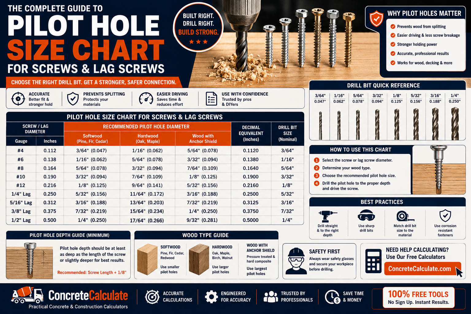
Pilot Hole Size Chart
Wood Screws, Lag Screws & Fasteners
The complete pilot hole reference for contractors, woodworkers, and DIYers, covering wood screws, lag screws, deck screws, structural screws, self-tapping screws, and concrete screws.
 Reviewed by Muhammad Ramzan Babar, PhD Researcher (Plasma Physics) & Calculator Developer — View Profile
⭐ Pilot Hole Size Chart
There is no single universal pilot hole size. The correct hole depends on fastener type, diameter, thread design, and material, so the tables below are separated by fastener family.
| Screw Size | Shank Diameter | Softwood Pilot | Hardwood Pilot | Clearance Hole |
|---|---|---|---|---|
| #2 | 0.086″ | 1/16″ | 3/64″ | 5/64″ |
| #4 | 0.112″ | 1/16″ | 1/16″ | 7/64″ |
| #6 | 0.138″ | 5/64″ | 5/64″ | 9/64″ |
| #8 | 0.164″ | 3/32″ | 3/32″ | 5/32″ |
| #10 | 0.190″ | 7/64″ | 7/64″ | 3/16″ |
| #12 | 0.216″ | 1/8″ | 1/8″ | 7/32″ |
| #14 | 0.242″ | 1/8″ | 9/64″ | 1/4″ |
| Lag Diameter | Dense Wood (G>0.6) | Medium (0.5<G≤0.6) | Low Density (G≤0.5) | Shank Clearance |
|---|---|---|---|---|
| 1/4″ | 5/32″-7/32″ | 5/32″-3/16″ | 3/32″-11/64″ | 1/4″ |
| 3/8″ | 1/4″-5/16″ | 7/32″-9/32″ | 5/32″-17/64″ | 3/8″ |
| 1/2″ | 21/64″-27/64″ | 19/64″-3/8″ | 13/64″-11/32″ | 1/2″ |
| 3/4″ | 31/64″-41/64″ | 29/64″-9/16″ | 19/64″-17/32″ | 3/4″ |
These two tables cover the two most common fastener families. Full wood screw sizes #2 through #14, the complete NDS-based lag screw density table, deck screws, self-tapping screws, and concrete screws each have their own dedicated chart further down this page, since mixing all fastener types into one table hides important differences in how each one is sized.
How to Read These Charts
A pilot hole for a wood screw is a lead hole: sized smaller than the screw so threads can grip. A lag screw connection uses two holes: a clearance hole sized to the shank, and a separate, smaller lead hole sized by wood density. See the Pilot Hole vs Lead Hole vs Clearance Hole section below for the full explanation.
What Is a Pilot Hole?
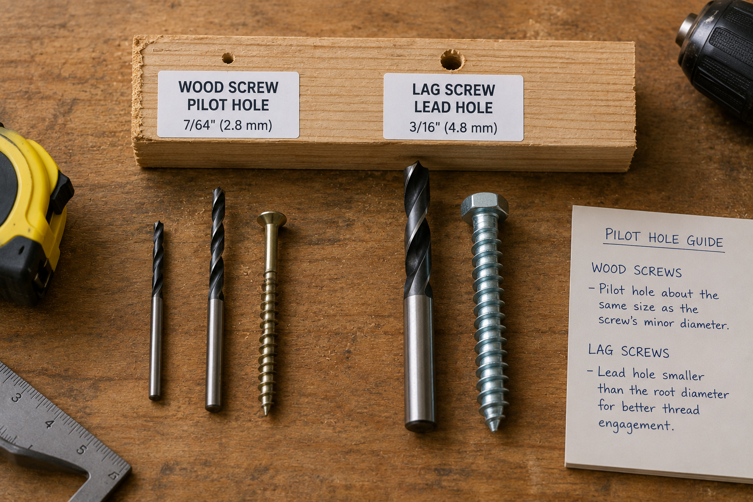
A predrilled hole that guides a fastener along a straight, predictable path instead of forcing it to displace material on its own.
A pilot hole is not simply a hole slightly smaller than the screw. Its correct diameter depends on the screw’s thread design, its root and shank diameters, and the density of the material. A hole sized correctly for a softwood 2×4 will behave very differently in dense oak or in sheet metal.
- Guides the fastener along the intended path
- Reduces driving resistance so the screw seats without excessive force
- Reduces the risk of splitting, especially near edges and ends
- Improves alignment when multiple fasteners are installed in a row
- Protects the fastener from thread damage or breakage during installation
⭐ Pilot Hole vs Lead Hole vs Clearance Hole
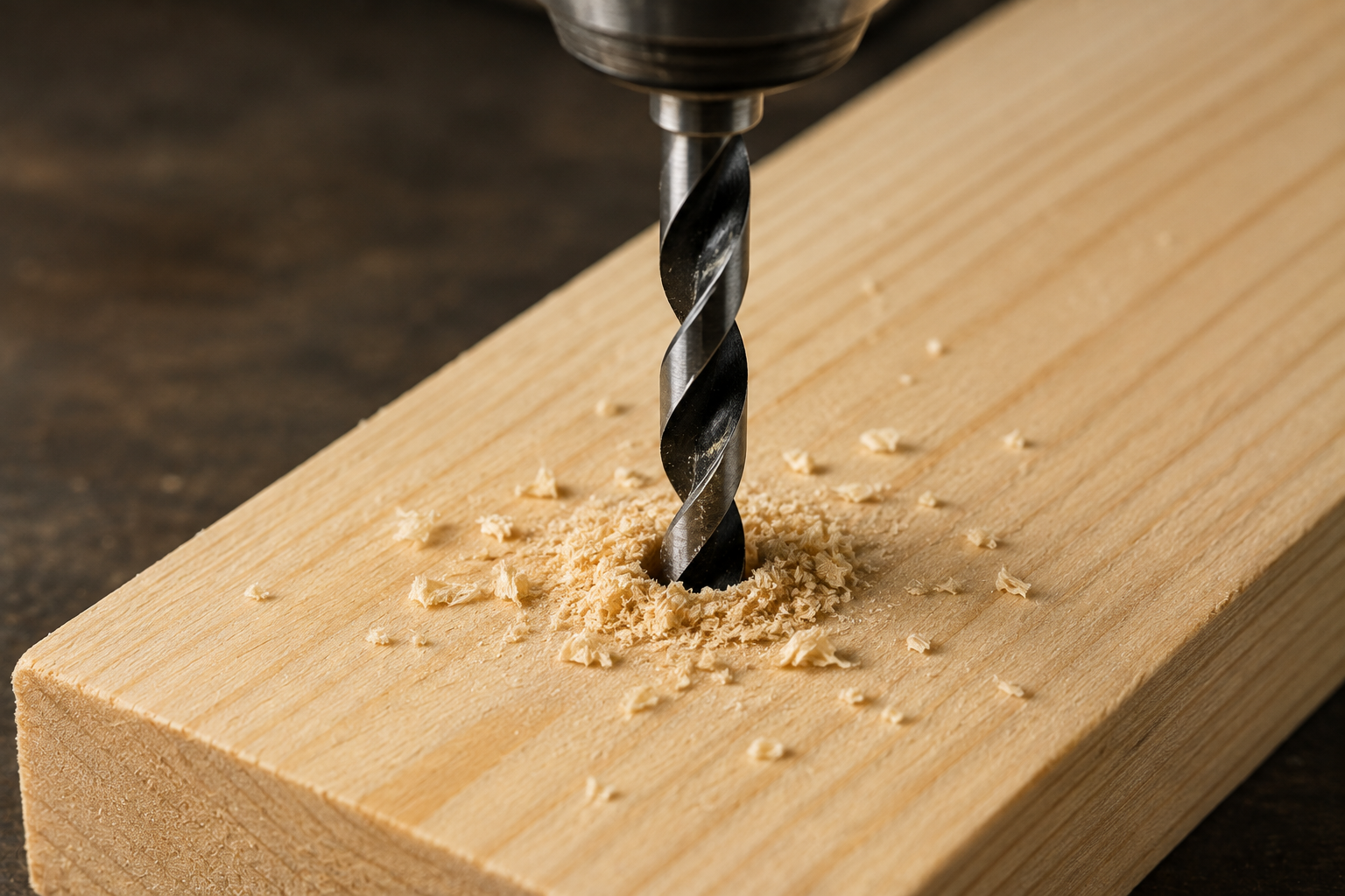
These terms are used loosely, but they describe distinct functions, and the distinction matters most for lag screws.
| Term | Definition | Typical Use |
|---|---|---|
| Pilot hole | General term for any predrilled hole that guides a fastener | Wood screws, deck screws |
| Lead hole | Sized so the threaded portion can engage and grip the material | Lag screws, wood screws |
| Clearance hole | Large enough that the unthreaded shank passes through freely | Lag screw upper member, bolted connections |
Per the American Wood Council’s 2018 NDS Section 12.1.4.2, a lag screw connection uses a clearance hole sized to match the shank diameter through the member the shank passes through, while the threaded portion receives a smaller lead hole in the member the threads must grip, sized as a percentage of the shank diameter based on wood specific gravity.
Why Pilot Holes Matter
A correctly sized pilot hole affects the outcome of a fastening job in several measurable ways.
- Preventing splitting. Without a pilot hole, a screw driven near an edge or end can wedge wood fibers apart faster than they compress, cracking the piece.
- Reducing driving torque. A pilot hole removes material ahead of the threads, lowering resistance on the driver.
- Improving alignment. A predrilled hole keeps the fastener from wandering off-axis when fasteners are spaced in a row.
- Reducing fastener breakage. Driving into dense material without a pilot hole increases the chance of snapping the head or stripping the drive recess.
- Protecting threads. A properly sized lead hole reduces thread damage compared to forcing threads through unrelieved material.
- Improving repeatability. Consistent pilot holes produce a consistent finished appearance across multiple fasteners.
Not always required
Many modern self-drilling and self-tapping screws cut or form their own path, and some structural wood screws are engineered for installation without predrilling. Always check the fastener manufacturer’s instructions before assuming a pilot hole is required.
Do All Screws Need Pilot Holes?
No. Whether a pilot hole is needed depends entirely on the fastener design and the material.
| Fastener Type | Typical Pilot Hole Need |
|---|---|
| Traditional wood screws | Commonly recommended, especially in hardwood and near edges |
| Traditional lag screws | Proper lead and clearance holes are important for structural connections |
| Modern construction/structural screws | Some need no predrilling; follow the manufacturer’s data sheet |
| Self-drilling screws | Often designed to drill their own starting hole |
| Concrete and masonry screws | Require a properly sized masonry hole per the product’s data |
Manufacturer guidance illustrates why this varies by product: some structural wood screws from manufacturers such as Simpson Strong-Tie are designed to install without a separate pilot hole in many applications, while fastener makers such as SPAX explicitly note that their no-predrilling guidance for certain wood fasteners does not extend to concrete or masonry, which always requires a properly sized masonry hole. Always defer to the specific product’s installation instructions over any generic chart.
Choosing the Correct Pilot Hole Size
Use this sequence for any fastener and material combination.
Selection Process
Pilot Hole Size by Fastener Type
A high-level comparison across common construction fasteners.
| Fastener | Typical Hole Approach |
|---|---|
| Wood screw | Lead/pilot hole sized to screw gauge and wood density |
| Lag screw | Clearance hole plus a separate lead hole based on specific gravity |
| Structural wood screw | Product-specific; some require no predrilling |
| Deck screw | Product-specific and material-specific |
| Self-tapping screw | Thread-specific pilot hole sized to material thickness/hardness |
| Self-drilling screw | Often no separate pilot hole needed |
| Concrete screw | Masonry pilot hole sized per manufacturer data |
| Machine screw | Tapped hole rather than an ordinary pilot hole |
⭐ Wood Screw Pilot Hole Size Chart
Full range #2 through #14, reconciled with ANSI/ASME B18.6.1 reference sizes, straight bit.
| Screw Size | Shank Diameter | Softwood Pilot | Hardwood Pilot | Clearance Hole |
|---|---|---|---|---|
| #2 | 0.086″ | 1/16″ | 3/64″ | 5/64″ |
| #3 | 0.099″ | 1/16″ | 1/16″ | 7/64″ |
| #4 | 0.112″ | 1/16″ | 1/16″ | 7/64″ |
| #5 | 0.125″ | 1/16″ | 5/64″ | 1/8″ |
| #6 | 0.138″ | 5/64″ | 5/64″ | 9/64″ |
| #7 | 0.151″ | 5/64″ | 3/32″ | 5/32″ |
| #8 | 0.164″ | 3/32″ | 3/32″ | 5/32″ |
| #9 | 0.177″ | 3/32″ | 7/64″ | 11/64″ |
| #10 | 0.190″ | 7/64″ | 7/64″ | 3/16″ |
| #11 | 0.203″ | 7/64″ | 1/8″ | 13/64″ |
| #12 | 0.216″ | 1/8″ | 1/8″ | 7/32″ |
| #13 | 0.229″ | 1/8″ | 9/64″ | 15/64″ |
| #14 | 0.242″ | 1/8″ | 9/64″ | 1/4″ |
Shank diameters follow ANSI/ASME B18.6.1 standard wood screw dimensions. Even-numbered sizes are anchored to the ANSI B18.6.1 pilot hole reference table; odd-numbered sizes follow the same progression as published trade fastener charts. Different published charts vary slightly depending on whether a tapered or straight bit is assumed; this chart uses straight-bit values throughout.
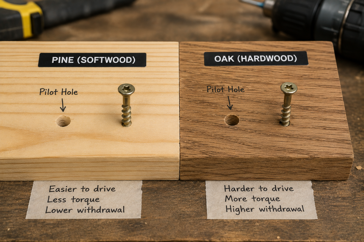
Common softwoods include pine, fir, spruce, and cedar. Their lower density and more compressible fiber structure let a screw displace material as it drives without splitting, so the pilot hole can generally be smaller than the equivalent hardwood hole while still providing adequate thread engagement. Common hardwoods include oak, maple, hickory, and walnut. Because dense hardwood resists fiber displacement, a larger pilot hole is generally appropriate to reduce splitting, driving torque, screw breakage, and thread damage. Softwood pilot holes matter most for larger gauges (#10 and up) and near edges or ends, where splitting risk rises regardless of species.
⭐ Hardwood vs Softwood Pilot Hole Chart
Direct comparison showing where softwood and hardwood pilot hole values actually diverge.
| Screw Size | Softwood Pilot | Hardwood Pilot | Difference |
|---|---|---|---|
| #4 | 1/16″ | 1/16″ | None at this size |
| #6 | 5/64″ | 5/64″ | None at this size |
| #8 | 3/32″ | 3/32″ | None at this size |
| #10 | 7/64″ | 7/64″ | None at this size |
| #12 | 1/8″ | 1/8″ | None at this size |
| #14 | 1/8″ | 9/64″ | 1/64″ larger in hardwood |
Why the values converge at small sizes
At small screw gauges, ANSI B18.6.1 reference values for softwood and hardwood are often identical or one drill size apart, because the absolute thread engagement area is small either way. The gap widens at larger gauges and is far more pronounced for lag screws, where the NDS ties the lead hole directly to wood specific gravity rather than a simple softwood/hardwood label.
Plywood, MDF & Particleboard
Engineered wood panels behave differently from solid lumber and should not automatically use solid-wood values.
| Material | Key Risk | Guidance |
|---|---|---|
| Plywood (face) | Veneer delamination, blow-through on thin panels | Softwood solid-wood value is a reasonable starting point; test on scrap |
| Plywood (edge) | Layer separation, higher splitting risk | Pilot hole strongly recommended |
| MDF | Edge splitting, thread stripping, no long fibers to grip | Pilot hole recommended even for small screws |
| Particleboard | Local crushing, weak repeated fastening | Use manufacturer-specific screws (for example, confirmat-style) where possible |
Plywood is built from cross-laminated veneer layers with alternating grain direction, which can cause uneven resistance as a screw passes through multiple layers, and face drilling is generally more forgiving than edge drilling. MDF and particleboard have no long grain fibers, so they crush and strip differently than solid wood or plywood; overdriving compresses the panel around the head and reduces holding strength. Do not apply a solid-wood pilot hole chart to these materials without qualification, and always follow product-specific pilot hole guidance for cabinetry-grade panel screws.
Composite Decking & Deck Screws
Deck screw pilot hole sizing is dictated by the decking material and the specific fastening system, not screw diameter alone.
| Decking Material | General Pilot Hole Guidance |
|---|---|
| Softwood decking (pressure-treated pine, fir) | Often installed without a pilot hole, except near board ends |
| Hardwood decking (ipe, cumaru, exotics) | Pilot hole almost always required due to extreme density |
| Pressure-treated lumber | Same density-based logic as softwood, adjusted for moisture |
| Composite decking | Manufacturer-specific; often required near ends and in cold weather |
| PVC decking | Manufacturer-specific; oversized holes sometimes required for thermal movement |
Diameter alone does not determine pilot hole size
The screw’s design (thread type, tip style, coating) and the decking manufacturer’s installation guide matter as much as diameter. Near board ends and edges, a pilot hole is almost always recommended regardless of material.
Composite and PVC decking are engineered products that can mushroom or crack near board ends without a pilot hole, particularly in cold weather when the material is more brittle. Some modern deck screws are engineered to avoid predrilling in standard wood decking, while composite and PVC boards frequently still call for a pilot hole depending on the product and installation temperature. For material quantity planning, see the Decking Calculator.
⭐ Lag Screw Pilot Hole Chart
NDS-based sizing by wood specific gravity, not a simple softwood/hardwood label.
| Lag Diameter | Dense Wood (G>0.6) | Medium-Density (0.5<G≤0.6) | Low-Density (G≤0.5) | Shank Clearance |
|---|---|---|---|---|
| 1/4″ | 5/32″ to 7/32″ | 5/32″ to 3/16″ | 3/32″ to 11/64″ | 1/4″ |
| 5/16″ | 13/64″ to 17/64″ | 3/16″ to 15/64″ | 1/8″ to 7/32″ | 5/16″ |
| 3/8″ | 1/4″ to 5/16″ | 7/32″ to 9/32″ | 5/32″ to 17/64″ | 3/8″ |
| 1/2″ | 21/64″ to 27/64″ | 19/64″ to 3/8″ | 13/64″ to 11/32″ | 1/2″ |
| 5/8″ | 13/32″ to 17/32″ | 3/8″ to 15/32″ | 1/4″ to 7/16″ | 5/8″ |
| 3/4″ | 31/64″ to 41/64″ | 29/64″ to 9/16″ | 19/64″ to 17/32″ | 3/4″ |
Lead hole ranges calculated from AWC 2018 NDS Section 12.1.4.2: 65 to 85 percent of shank diameter for G greater than 0.6, 60 to 75 percent for 0.5 less than G up to 0.6, and 40 to 70 percent for G at or below 0.5. Use the larger percentage in each range for larger lag screw diameters. The shank clearance hole always equals the nominal shank diameter, per NDS 12.1.4.2(a). NDS Section 12.1.4.3 notes that lead and clearance holes are not required for 3/8 inch and smaller lag screws loaded primarily in withdrawal in wood with G at or below 0.5, provided edge and end distances are sufficient.
Rather than relying only on the labels softwood and hardwood, the NDS ties lag screw lead-hole sizing to specific gravity (G), a direct measure of wood density, because species within the same softwood or hardwood category can have meaningfully different densities. A dense softwood species and a lighter hardwood species can have overlapping specific gravity values, which is why a lead hole based purely on the softwood/hardwood label can be undersized or oversized for a particular species. For lag screw dimensional specifications rather than hole sizing, see the Screw Size Chart.
Lag Screw Clearance Hole vs Lead Hole
A lag screw connection uses two different holes in two different wood members.
Diagram is schematic and illustrates the NDS clearance hole and lead hole concept for lag screw connections; it is not to scale for any specific lag screw diameter.
The clearance hole is drilled through the member the unthreaded shank passes through, sized to match the shank diameter exactly. The lead hole is drilled into the member that receives the threaded portion, sized smaller than the shank so threads can engage and grip the wood. Any structural ledger, post, or beam connection using lag screws should be verified against the applicable design standard, local code, and, where the connection is load-bearing, a qualified engineer.
Structural & Construction Screws
Proprietary, engineered fasteners with product-specific pilot hole requirements.
| Fastener | Typical Predrilling Guidance |
|---|---|
| Structural wood screws | Many designed for no predrilling in standard framing lumber; check the code evaluation report |
| Construction screws (self-drilling/tapping tips) | Often no pilot hole needed in softwood framing; hardwood or dense engineered lumber still often benefits from one |
Structural wood screws often use specialized cutting or self-drilling tip geometry, serrated or reversed threads near the head to reduce splitting without a pilot hole, and manufacturer-specified drill sizes for certain materials. Manufacturers such as Simpson Strong-Tie publish technical notes stating that certain structural wood screws require no predrilling for specific applications, which is why a generic lag-screw lead-hole table should not automatically be applied to a proprietary structural screw. Always consult the specific product’s code report or installation guide rather than a generic chart.
⭐ Self-Tapping & Self-Drilling Screws
Sheet-metal screw pilot hole sizing follows different logic than wood screws.
| Screw Size | Major Diameter | Soft Metal / Plastic | Hard Metal |
|---|---|---|---|
| #6 | 0.138″ | 0.104″ (#37 drill) | 0.113″ (#33 drill) |
| #8 | 0.164″ | 0.128″ (#30 drill) | 0.136″ (#29 drill) |
| #10 | 0.190″ | 0.152″ (#24 drill) | 0.161″ (#20 drill) |
| #12 | 0.216″ | 0.177″ (#16 drill) | 0.185″ (#13 drill) |
| #14 | 0.242″ | 0.201″ (#7 drill) | 0.209″ (#4 drill) |
Values represent commonly published thread-forming/thread-cutting sheet-metal screw pilot hole references for Type AB and Type B style screws. Confirm against the specific manufacturer’s data, since thread form and material hardness both affect the correct size.
Self-tapping screws cut their own internal threads as they are driven into a pre-existing pilot hole. Type A, Type AB, and Type B screws differ in thread pitch and point design, changing the correct pilot hole diameter for the same nominal size; do not mix these categories. Self-drilling screws include a drill-point tip that cuts its own starting hole, so a separate pilot hole is often unnecessary within the material thickness range the drill point is rated for; exceeding that range can cause the drill point to fail before threads engage. Always check the manufacturer’s rated thickness before skipping a pilot hole.
Pilot Holes for Metal Screws
Metal screw sizing depends on metal type, sheet thickness, and thread-forming vs thread-cutting design.
- Sheet-metal screws generally need a pilot hole close to the screw’s minor (root) diameter for adequate thread engagement.
- Thread-cutting screws physically remove material to form threads and typically need a slightly larger pilot hole than thread-forming screws of the same size.
- Thread-forming screws displace material rather than cutting it, generally needing a smaller pilot hole for the same nominal size.
- Steel versus aluminum: aluminum is softer and more forgiving of pilot hole variance; hardened steel requires more precise sizing.
- Thin versus thick sheet: thin sheet metal strips more easily and may need a slightly smaller pilot hole than thick stock for the same screw.
Do not mix metal pilot-hole values with wood-screw values; the two follow entirely different engineering logic. See the Self-Tapping Screws chart above for representative sheet-metal pilot hole values by screw size.
Equipment for Your Project
Affiliate disclosure: As an Amazon Associate, ConcreteCalculate earns from qualifying purchases. We may also earn a commission from other affiliate links at no additional cost to you.
⭐ Concrete & Masonry Screw Chart
Requires a carbide-tipped masonry bit and a hole diameter smaller than the screw’s outer diameter.
| Screw Diameter | Masonry Pilot Bit | Minimum Embedment |
|---|---|---|
| 3/16″ | 5/32″ | 1″ |
| 1/4″ | 3/16″ | 1″ |
| 3/8″ | 5/16″ | 1-1/2″ |
| 1/2″ | 7/16″ | 2″ |
Values reflect widely published manufacturer technical data for concrete screw anchors. Exact drill bit size, minimum embedment, and hole depth vary by manufacturer and product line, so always confirm against the specific fastener’s installation instructions.
- Carbide masonry bits are required; standard twist bits will not cut concrete or block efficiently and wear out quickly.
- Hole depth should always be drilled deeper than the required thread embedment, commonly 1/4 to 1/2 inch or more, to prevent the screw from bottoming out on drilling dust.
- Cleaning the hole of dust and debris before installation matters, since packed dust can prevent full embedment.
- Manufacturer requirements always take precedence over general guidance.
Pilot Hole vs Tap Drill Hole
Different processes for different fastening systems.
| Process | Sequence |
|---|---|
| Wood or lag screw | Drill pilot/lead hole, then drive the screw directly |
| Machine screw | Drill tap drill hole, cut threads with a tap, then thread in the screw |
A pilot hole guides a wood, lag, or self-tapping fastener that forms or cuts its own thread engagement as it is driven. A tap drill hole is prepared specifically so a tap can cut precise internal machine threads, which a machine screw is then threaded into. For internal machine-thread sizing, see the Tap Drill Chart.
Pilot Hole Diameter vs Screw Diameter
A common misconception clarified.
A common misconception is that the pilot hole should equal the screw’s outside (major) diameter. For a threaded wood screw or lag screw driven into a lead hole, this is not correct: the threads need surrounding material to engage and grip, so the lead hole is sized smaller than the major diameter, closer to a percentage of the root or shank diameter depending on the fastener and the NDS provisions covered earlier on this page. For a clearance hole, the relationship is different: the hole is intentionally sized to match or very slightly exceed the shank diameter, so the shank passes through without engaging the material at all.
Pilot Hole Depth
Depth should generally match or slightly exceed the embedded thread length, with exceptions.
- Blind holes should be drilled a bit deeper than the screw’s tip length to avoid bottoming out before the screw is fully seated.
- Through holes do not have a bottoming-out risk, but debris clearance is still worth accounting for.
- Additional depth for debris matters most in masonry; manufacturer instructions for concrete screws commonly call for drilling 1/4 inch or more deeper than the required embedment specifically to leave room for dust.
⭐ Drill Bit Conversion Chart
Fractional, decimal, and metric equivalents, since pilot hole charts often mix all three systems.
| Fractional Size | Decimal Equivalent | Metric Equivalent |
|---|---|---|
| 1/16″ | 0.0625″ | 1.59 mm |
| 5/64″ | 0.0781″ | 1.98 mm |
| 3/32″ | 0.0938″ | 2.38 mm |
| 7/64″ | 0.1094″ | 2.78 mm |
| 1/8″ | 0.1250″ | 3.18 mm |
| 9/64″ | 0.1406″ | 3.57 mm |
| 5/32″ | 0.1563″ | 3.97 mm |
| 11/64″ | 0.1719″ | 4.37 mm |
| 3/16″ | 0.1875″ | 4.76 mm |
| 13/64″ | 0.2031″ | 5.16 mm |
| 7/32″ | 0.2188″ | 5.56 mm |
| 15/64″ | 0.2344″ | 5.95 mm |
| 1/4″ | 0.2500″ | 6.35 mm |
Metric values are approximate equivalents, not necessarily interchangeable drill sizes. For precise fits, use calipers to compare the actual bit diameter to the required decimal size.
To match an unmarked bit to this chart: check the shank or packaging for a printed size first, use a drill-bit gauge plate with stamped holes for fractional, numbered, and letter sizes, or measure directly with digital calipers for the most precise reading.
Tapered vs Straight Pilot Holes
Two different bit geometries that are not interchangeable.
| Bit Type | Shape | Common Use |
|---|---|---|
| Tapered | Cone-shaped, narrower near the tip, wider near the head | Matches traditional wood screw thread geometry; common in trim and cabinetry work |
| Straight | Constant diameter along the full depth | Standard twist bit; far more common in general construction |
This is why two published pilot hole charts for the same screw size can show different numbers. The chart on this page uses straight-bit values throughout for consistency with standard construction practice, and clearly distinguishes them from tapered-bit values where both are referenced.
Countersink & Counterbore After Pilot Drilling
A pilot hole is not the same thing as a countersink.
- Countersinking cuts a conical recess so a flat-head screw sits flush with or slightly below the surface.
- Counterboring cuts a flat-bottomed recess, typically for a pan-head or hex-head screw, sometimes deep enough for a wood plug.
- Head angle (commonly 82 degrees for U.S. flat-head screws) determines the correct countersink bit angle.
- Material thickness limits how deep a countersink or counterbore can go without weakening the piece.
The screw head type generally does not change the pilot or lead hole diameter, which is primarily determined by the screw’s shank or thread diameter, thread design, and material. What the head type affects is whether you also need a countersink, counterbore, or recess preparation. For screw head geometry and matching drive types, see the Screw Size Chart.
How to Drill a Pilot Hole Correctly
A practical, repeatable process.
Drilling Procedure
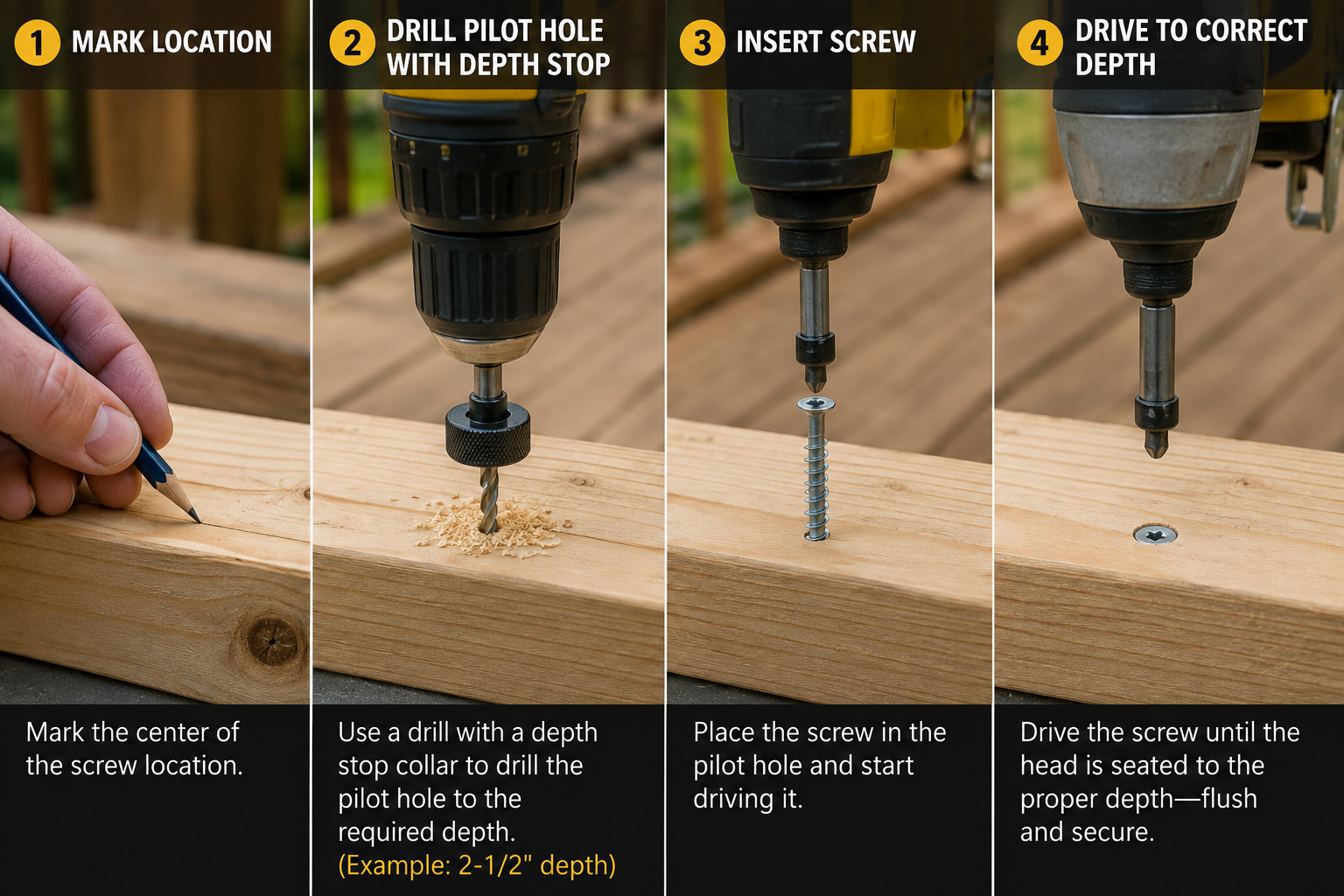
Pilot Hole Size Worked Examples
Real-world sizing decisions for common job scenarios.
#8 Wood Screw in Softwood
#10 Wood Screw in Hardwood
1/2 Inch Lag Screw in a Wood Connection
Deck Screw Near the Edge of a Hardwood Board
Concrete Screw in Masonry
Common Pilot Hole Sizing Mistakes
Errors that reduce holding strength or damage the material or fastener.
Pilot hole too small
Increases driving torque and risk of splitting or fastener breakage.
Pilot hole too large
Reduces thread engagement and holding strength.
Confusing lead hole with clearance hole
Produces a lag screw connection that either binds or has no grip.
Using wood-screw values for lag screws
Lag screws follow NDS specific-gravity-based sizing, not wood screw charts.
Using wood values for metal
Metal thread-forming and thread-cutting screws need entirely different logic.
Ignoring wood density
Treating all hardwoods or softwoods as equivalent overlooks real specific gravity differences.
Ignoring manufacturer instructions
Proprietary structural, deck, and masonry screws often override generic charts.
Drilling too shallow
Risks bottoming out the fastener before it seats or reaches embedment.
Drilling too deep
Can reduce holding strength or break through the opposite face.
Using the wrong bit type
Standard twist bits will not efficiently cut concrete or masonry.
Assuming all construction screws need predrilling
Many are engineered for direct installation in softwood framing.
Assuming no screw ever needs predrilling
Hardwood, dense engineered lumber, and masonry usually still require it.
Splitting & Driving Torque
Factors that interact with pilot hole size to affect both outcomes.
| Factor | Effect on Splitting | Effect on Torque |
|---|---|---|
| Screw diameter | Larger diameter increases risk without adequate pilot hole | Larger diameter increases torque |
| Wood species/density | Denser species split differently under the same force | Dense hardwood requires noticeably more torque |
| Grain direction | Fasteners near an end parallel to grain split more easily | Minimal direct effect |
| Edge/end distance | Close spacing concentrates stress, raising split risk | Minimal direct effect |
| Moisture content | Wetter wood is generally more prone to splitting | Minor effect |
| Pilot hole size | Undersized hole with an aggressive thread raises split risk | Smaller hole generally raises torque |
| Lubrication | No effect on splitting | Reduces torque; NDS notes lubrication does not reduce reference design values |
The AWC’s NDS commentary specifically notes that wood species, moisture content, and grain orientation all influence how fasteners affect the surrounding wood, which is why edge distance, end distance, and fastener spacing requirements in the NDS are based on wood properties rather than a single universal rule. As a general trend, a smaller pilot hole increases thread engagement and typically increases driving resistance, but this relationship is not perfectly linear once species density, screw length, and power-driver settings are factored in.
Pilot Hole Size Chart Limitations
Important context before applying any value on this page.
- Published pilot hole charts are not universally interchangeable; sources may assume tapered versus straight bits, or different species groupings.
- Fastener design (thread form, tip geometry, coating) significantly affects the correct pilot hole diameter for a given nominal size.
- Material matters as much as fastener size; wood, engineered panels, metal, and masonry each require different sizing logic.
- Wood density varies by species and even within a species, so specific gravity-based sizing is more precise than a softwood/hardwood label.
- Manufacturer specifications for structural, deck, composite, and masonry screws take precedence over any generic chart on this page.
- Structural or load-bearing wood connections should be verified against the applicable design standard and, where necessary, a qualified engineer.
- Self-drilling screws may not require a separate pilot hole at all, depending on the drill point design and material thickness rating.
- Structural screws frequently have proprietary installation requirements documented in a code evaluation report.
Standards & Technical References
The authoritative sources behind this chart.
| Reference | What It Covers |
|---|---|
| AWC National Design Specification (NDS) | Structural wood connections, including lag screw and wood screw lead hole, clearance hole, withdrawal, and lateral design provisions |
| ANSI/ASME B18.2.1 | Standard dimensions for hex bolts and hex lag screws referenced by the NDS |
| ANSI/ASME B18.6.1 | Standard dimensions and pilot hole reference data for wood screws |
| Manufacturer technical data | Critical for structural screws, deck screws, construction screws, masonry screws, and self-drilling fasteners |
The American Wood Council also publishes a connection calculator supporting bolts, nails, lag screws, and wood screws under the current NDS provisions; this pilot hole chart is a reference for hole sizing, not a substitute for a structural connection capacity calculation. Always confirm current edition requirements and manufacturer-specific installation instructions before finalizing a structural connection design.
Frequently Asked Questions
📥 Download Pilot Hole Size Chart PDF
Use your browser’s print function to instantly save this page as a PDF, for jobsite binders, workbenches, and reference kits.