Deck Post Spacing Chart 2026 – IRC Beam Span & Post Layout
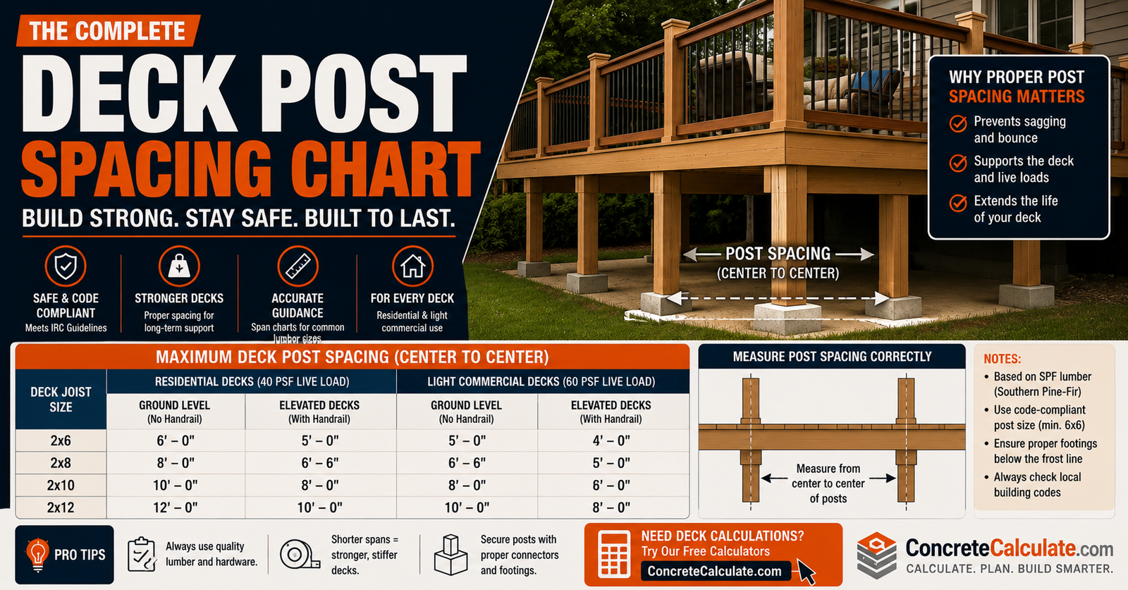
Deck Post Spacing Chart
IRC Beam Span & Post Layout
Maximum deck post spacing is controlled by the allowable beam span between supports, not by a fixed universal distance. This chart shows how beam size, species, joist span and load determine spacing, plus post height, tributary area and footing sizing.
 Reviewed by Muhammad Ramzan Babar, PhD Researcher & Calculator Developer · View Profile
Post spacing is effectively the beam span between supports. It depends on beam size, number of plies, species, joist span, joist cantilever, snow load and dead load together. A number that works for one beam and one deck can be unsafe for another.
⭐⭐⭐⭐⭐ Deck Post Spacing Chart: Quick Reference
Maximum beam span between posts for common Southern Pine multi-ply beams, based on published IRC R507.5 span data. Beam span between posts is the effective post spacing for that beam line.
| Beam Size | Joist Span 6 ft | Joist Span 10 ft | Joist Span 14 ft | Joist Span 18 ft |
|---|---|---|---|---|
| 2-ply 2×8 | 8′-6″ | 6′-6″ | 5′-6″ | 4′-9″ |
| 2-ply 2×10 | 10′-1″ | 7′-9″ | 6′-6″ | 5′-9″ |
| 2-ply 2×12 | 11′-11″ | 9′-2″ | 7′-9″ | 6′-9″ |
| 3-ply 2×10 | 12′-9″ | 9′-9″ | 8′-3″ | 7′-3″ |
| 3-ply 2×12 | 15′-0″ | 11′-7″ | 9′-9″ | 8′-7″ |
Values shown are for Southern Pine, No. 2 grade or better, under a 40 psf live load and 10 psf dead load, based on published IRC Section R507.5 beam span data. Douglas Fir-Larch, Hem-Fir and Spruce-Pine-Fir use separate species-specific tables with generally shorter allowable spans. Higher snow loads use separate sub-tables with reduced spans. Always confirm the exact figure against the beam span table adopted by your local jurisdiction.
⭐⭐⭐⭐⭐ What Is Deck Post Spacing?
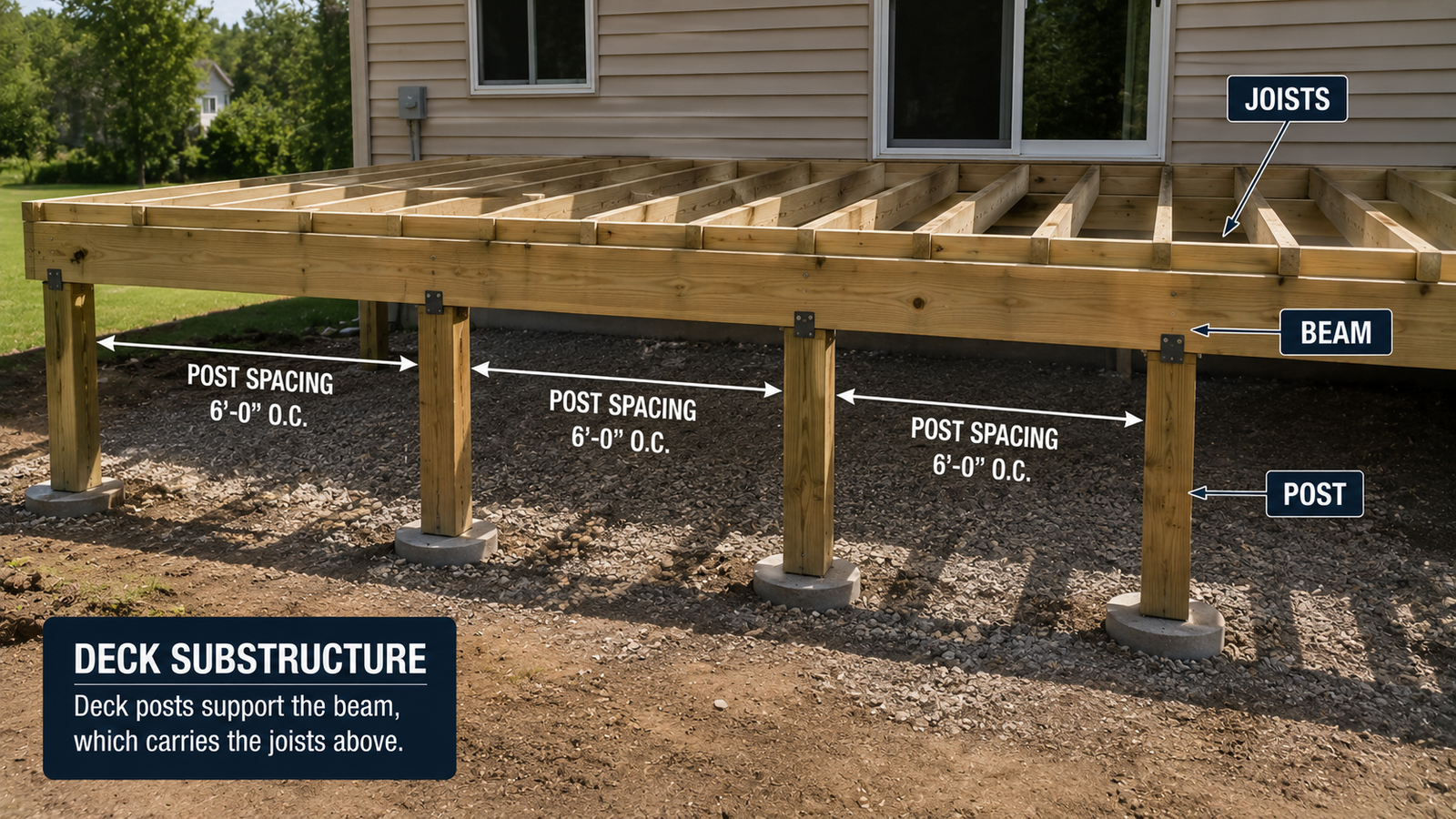
Deck post spacing is the distance between adjacent support posts, normally measured center to center.
Posts support the beam, the beam supports the joists, and the joists support the decking surface. Load travels down through this chain to the footings and ultimately into the soil.
Load path
Decking transfers load to joists, joists transfer load to the beam, the beam transfers load to posts, and posts transfer load to footings bearing on soil.
Why spacing matters
Each post is a support point for the beam. The distance between those support points is the beam’s span for that section, which directly governs whether the chosen beam size is adequate.
⭐⭐⭐⭐⭐ Deck Post Spacing vs Deck Beam Span
This is the most important concept on this page.
If posts support a beam, the distance between those posts is the span the beam must carry in that section. Maximum permissible post spacing therefore cannot be chosen independently of beam size, species, joist span and load condition. Choosing a post spacing first and hoping a beam fits it reverses the correct design order.
The practical implication is that “how far apart can my deck posts be” and “how far can my beam span between supports” are effectively the same engineering question. See the Deck Beam Span Chart for expanded beam span data by species and load condition.
⭐⭐⭐⭐ How Deck Post Spacing Is Measured
Spacing is measured center to center between support points, not as clear distance between post faces.
Center-to-center spacing
The standard measurement runs from the centerline of one post to the centerline of the next along the beam.
End posts vs interior posts
End posts typically sit near the corners of the beam run, while interior posts are placed between them to break the beam into shorter spans.
Beam support points
Each post location is a support point. The beam span table applies to the distance between each pair of adjacent support points.
Beam cantilever/overhang
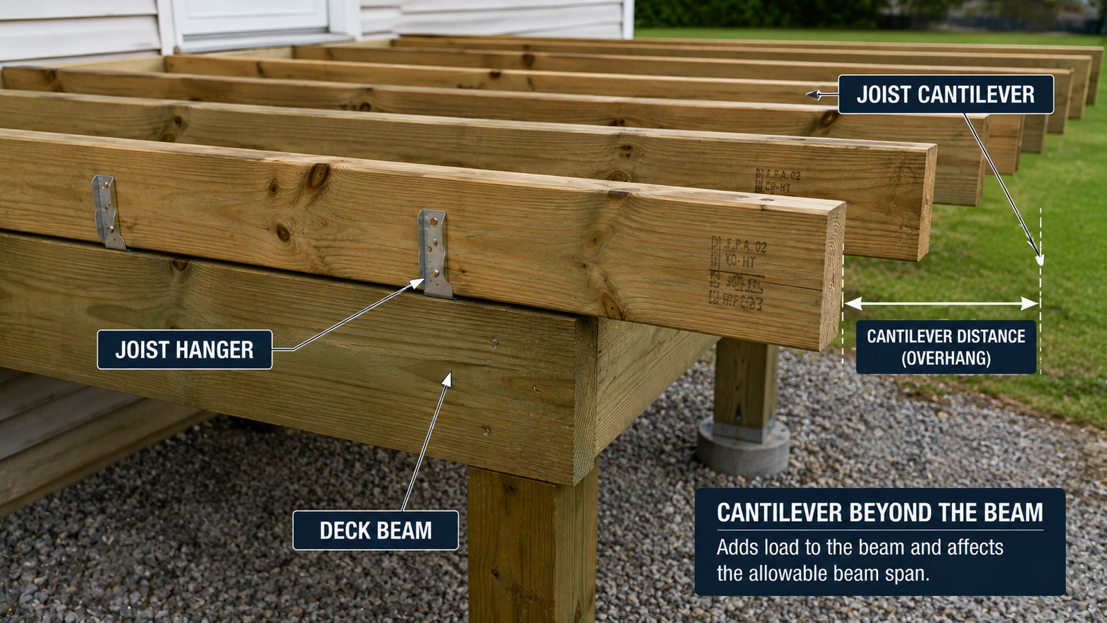
Where the beam extends past the end post, that overhang is a cantilever, evaluated separately from the backspan between posts.
⭐⭐⭐⭐⭐ What Controls Maximum Deck Post Spacing?
Multiple variables interact to determine the actual allowable spacing for a given beam.
Beam size and plies
Larger dimension lumber and additional plies generally increase allowable span.
Lumber species and grade
Span tables are species-specific; No. 2 grade or better is the baseline assumption behind IRC prescriptive values.
Joist span and cantilever
Longer joist spans and longer joist cantilevers increase the load carried by the beam, reducing allowable beam span.
Live load, snow load and dead load
Higher load assumptions reduce allowable beam span at a given size.
Wet-service conditions
Treated lumber used outdoors is evaluated under wet-service design values, which can differ from dry-use assumptions.
Beam cantilever and prescriptive vs engineered design
Beam overhang past a post has its own limit, and spans beyond prescriptive table limits require engineered design.
⭐⭐⭐⭐⭐ 2024 IRC Deck Beam Span and Post Spacing
Section R507.5 contains the prescriptive beam span tables that effectively govern post spacing.
The 2024 IRC revised the beam span table column headings to show multiple joist span and cantilever combinations that produce an equivalent beam load, rather than assuming every joist is cantilevered to its maximum length as earlier editions did. A design with a 12 foot joist span and a 1 foot cantilever can use the same table column as a 14 foot joist span with no cantilever, since both produce a comparable load on the beam. This allows more accurate, often smaller, beam sizing when a design has little or no cantilever.
Section R507.5 contains separate beam span tables organized by lumber species (Southern Pine, Douglas Fir-Larch, Hem-Fir, and Spruce-Pine-Fir) and by ground snow load condition. The rows in each table represent beam span, meaning the center-to-center distance between posts. Selecting the correct table for species and load, then reading the row matching the desired beam span, gives the minimum required beam size for that post spacing.
⭐⭐⭐⭐⭐ Deck Post Spacing by Beam Size
Maximum beam span (post spacing) for common Southern Pine multi-ply beam configurations, based on published IRC R507.5 data.
| Beam Size | Joist Span | Max Post Spacing | Species | Loading Basis |
|---|---|---|---|---|
| 2-ply 2×8 | 6 ft | 8′-6″ | Southern Pine | 40 psf live / 10 psf dead |
| 2-ply 2×8 | 14 ft | 5′-6″ | Southern Pine | 40 psf live / 10 psf dead |
| 2-ply 2×10 | 6 ft | 10′-1″ | Southern Pine | 40 psf live / 10 psf dead |
| 2-ply 2×10 | 14 ft | 6′-6″ | Southern Pine | 40 psf live / 10 psf dead |
| 2-ply 2×12 | 6 ft | 11′-11″ | Southern Pine | 40 psf live / 10 psf dead |
| 2-ply 2×12 | 14 ft | 7′-9″ | Southern Pine | 40 psf live / 10 psf dead |
| 3-ply 2×10 | 6 ft | 12′-9″ | Southern Pine | 40 psf live / 10 psf dead |
| 3-ply 2×10 | 14 ft | 8′-3″ | Southern Pine | 40 psf live / 10 psf dead |
| 3-ply 2×12 | 6 ft | 15′-0″ | Southern Pine | 40 psf live / 10 psf dead |
| 3-ply 2×12 | 14 ft | 9′-9″ | Southern Pine | 40 psf live / 10 psf dead |
These species groups use separate tables with generally shorter allowable spans than Southern Pine, particularly for incised (pressure-treated) lumber. Do not apply Southern Pine values to a different species.
⭐⭐⭐⭐⭐ Deck Post Spacing by Joist Span
Longer joists increase the tributary load carried by the beam, which reduces the beam’s allowable span at a fixed size.
The quick reference and beam-size tables above already organize allowable spacing by joist span in 4-foot increments common to published span data. As joist span increases from 6 to 18 feet, allowable beam span between posts decreases for every beam size and ply count shown, since each additional foot of joist span adds more load per linear foot of beam. For expanded joist-specific data, see the Deck Joist Span Chart.
⭐⭐⭐⭐⭐ Deck Post Spacing and Joist Cantilever
The 2024 IRC change makes this relationship especially relevant.
A joist cantilever adds load to the beam beyond what the backspan alone would produce, because the overhanging portion of the joist still bears on the beam as a lever. The 2024 IRC beam span table columns account for this by grouping joist span and cantilever combinations that produce an equivalent beam load into the same column, rather than requiring a separate modifier calculation.
In practice, this means a design with a shorter joist backspan and a longer cantilever can load the beam similarly to a design with a longer backspan and no cantilever. Both conditions can share the same table column and therefore the same allowable beam span between posts. Always match the actual backspan and cantilever combination to the correct table column rather than assuming zero cantilever.
⭐⭐⭐⭐ Deck Post Spacing by Beam Species
Identical beam dimensions can have different allowable spans depending on species.
Southern Pine
Generally provides the longest allowable spans among common framing species in published IRC tables.
Douglas Fir-Larch
Uses its own span table; incising for pressure treatment can meaningfully reduce allowable spans compared to Southern Pine.
Hem-Fir
A separate species group table with its own design values, generally shorter spans than Southern Pine.
Spruce-Pine-Fir
Also evaluated under its own table; verify against the specific grade and treatment condition used.
Redwood and Western Cedars
Naturally durable species with their own span data, commonly used where a natural, untreated appearance is desired.
Why this matters
Never substitute one species’ span table value for another. A beam sized correctly for Southern Pine may be undersized if actually built from Hem-Fir or incised Douglas Fir-Larch.
⭐⭐⭐⭐⭐ Deck Post Spacing for 2-Ply vs 3-Ply Beams
Additional plies increase beam capacity and generally permit wider post spacing at the same lumber size.
| Beam | Joist Span 6 ft | Joist Span 14 ft |
|---|---|---|
| 2-ply 2×10 | 10′-1″ | 6′-6″ |
| 3-ply 2×10 | 12′-9″ | 8′-3″ |
| 2-ply 2×12 | 11′-11″ | 7′-9″ |
| 3-ply 2×12 | 15′-0″ | 9′-9″ |
Number of plies
A 3-ply beam combines three individual boards fastened as a single structural member, increasing overall section capacity compared to 2-ply.
Fastening requirement
Multi-ply beams must be fastened per code, commonly two rows of nails at specified spacing along each edge, so the plies act as a composite member rather than independent boards.
Post-bearing width
Wider multi-ply beams need adequate post cap or bearing width to fully support the assembled beam.
Table-specific values required
The actual span increase from adding a ply varies by size and joist span; always read the specific value from the applicable table rather than assuming a fixed percentage gain.
⭐⭐⭐⭐⭐ Deck Post Spacing for Common Beam Sizes
A consolidated reference for frequently searched beam and post spacing combinations.
| Search Term | Applicable Beam | Reference Spacing Range (Southern Pine) |
|---|---|---|
| 2×8 deck beam post spacing | 2-ply 2×8 | 4′-9″ to 8′-6″ depending on joist span |
| 2×10 deck beam post spacing | 2-ply 2×10 | 5′-9″ to 10′-1″ depending on joist span |
| 2×12 deck beam post spacing | 2-ply 2×12 | 6′-9″ to 11′-11″ depending on joist span |
| Double 2×8 post spacing | 2-ply 2×8 | Same as 2×8 row above |
| Double 2×10 post spacing | 2-ply 2×10 | Same as 2×10 row above |
| Triple 2×10 post spacing | 3-ply 2×10 | 7′-3″ to 12′-9″ depending on joist span |
These ranges summarize the beam-size table above for common search terms. Always identify the actual joist span and species for a specific project rather than picking a value from the middle of the range.
⭐⭐⭐⭐ Is 6-Foot Deck Post Spacing Acceptable?
Possibly, depending on the beam and loading, but it is not automatically required or automatically safe.
Six foot spacing falls comfortably within the allowable span for most beam sizes shown in the tables above, even at longer joist spans. However, “acceptable” still depends on confirming the actual beam size, species, joist span, snow or load condition, post capacity at that tributary area, and footing size for the specific design. A 6 foot spacing that works with a 3-ply 2×12 beam does not automatically mean the same spacing is adequate with a 2-ply 2×8 beam at a long joist span.
⭐⭐⭐⭐⭐ Is 8-Foot Deck Post Spacing Acceptable?
Often, but this is not a universal rule that applies to every beam and joist span combination.
Based on the reference table above, 8 foot spacing is achievable with a 2-ply 2×8 at a 6 foot joist span, a 2-ply 2×10 or larger at moderate joist spans, or a 3-ply beam at longer joist spans. It is not achievable with a 2-ply 2×8 at a 14 foot joist span, where the allowable span drops to about 5′-6″. Confirm the specific beam size and joist span combination against the applicable table before assuming 8 feet is safe.
⭐⭐⭐⭐⭐ Can Deck Posts Be 10 or 12 Feet Apart?
Only with a sufficiently sized beam and favorable joist span, and often at the edge of or beyond prescriptive table limits.
10 feet
Achievable with a 3-ply 2×10 at a short joist span, or a 3-ply 2×12 at a moderate joist span, based on the reference data above.
12 feet
Requires a large beam at a short joist span, such as a 3-ply 2×12 near a 6 foot joist span, and may approach or exceed standard prescriptive table limits depending on species and load.
Species matters
Douglas Fir-Larch, Hem-Fir and Spruce-Pine-Fir generally achieve shorter spans than Southern Pine at the same beam size, making 10 to 12 foot spacing harder to reach.
Beyond prescriptive limits
Spans beyond the applicable table’s maximum require an engineered beam design rather than a prescriptive lookup. See the Deck Beam Span Chart for expanded span data.
⭐⭐⭐⭐⭐ Deck Post Spacing and Tributary Area
Tributary area is the portion of deck load a specific post carries.
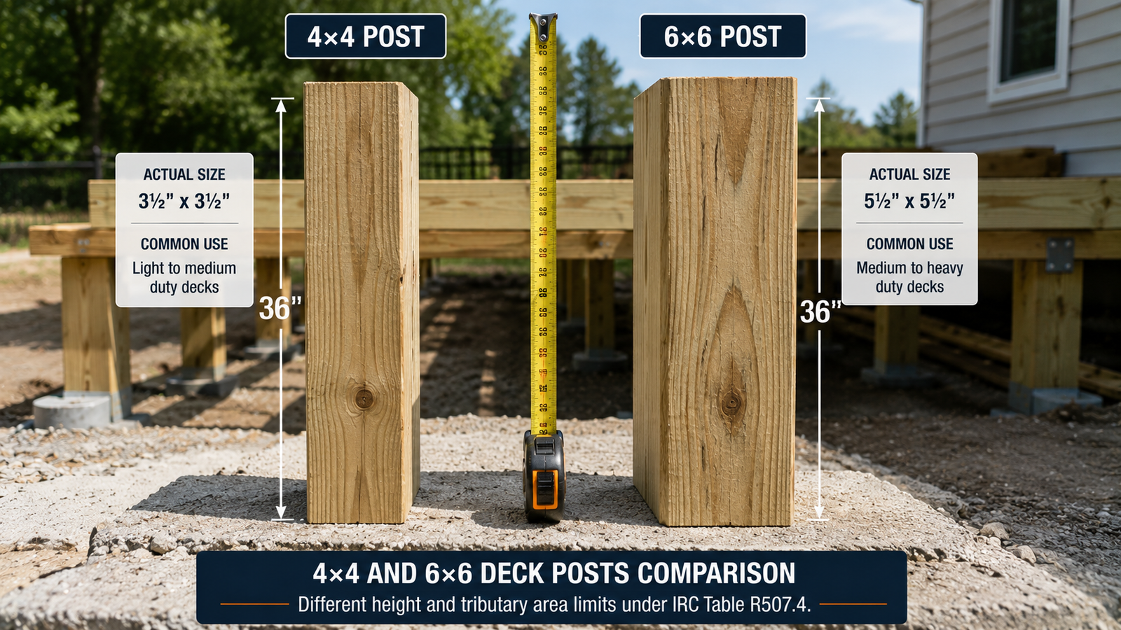
Each post supports a share of the deck based on half the beam span on one side of the post, half the beam span on the other side, and the tributary joist width feeding into that section of beam. IRC Table R507.4 uses tributary area, alongside post species and size, as a major input for determining allowable post height.
⭐⭐⭐⭐⭐ How to Calculate Tributary Area for a Deck Post
A simplified concept for estimating the load share each post carries.
Tributary area = tributary beam length x tributary joist width. For a typical interior post, tributary beam length is roughly half the beam span on each adjacent side added together, and tributary joist width is roughly half the joist span (or half the joist span plus any cantilever, depending on the sizing method used).
Interior post
Carries load from beam spans on both sides, generally producing the largest tributary area among post types on a given beam line.
End post
Typically carries load from one adjacent beam span plus any cantilever beyond it, often a smaller tributary area than an interior post.
Corner post
On a freestanding deck with beams in two directions, a corner post can combine tributary width from two framing directions.
Freestanding deck post
Without a ledger, every post carries a larger share of total deck load since there is no wall-supported side.
This simplified approach works for typical rectangular, single-level decks. Irregular shapes, multiple beam lines, or additional structures such as roofs can require a more detailed structural calculation.
⭐⭐⭐⭐⭐ Deck Post Size and Spacing
Post size affects the post’s own capacity, not the beam’s allowable span.
| Post Size | Maximum Height (Southern Pine, 40 psf live load) |
|---|---|
| 4×4 | 6′-9″ a |
| 4×6 | 8′-0″ |
| 6×6 | 14′-0″ |
| 8×8 | 14′-0″ |
a. Maximum permitted height for one-ply and two-ply beams; the maximum permitted height for a 4×4 post supporting a three-ply beam on a post cap is 6′-9″ per IRC Table R507.4 footnotes. Height is measured to the underside of the beam.
Beam span still needs to satisfy the beam span table regardless of the post size beneath it. Post size mainly affects the post’s own vertical capacity and maximum unbraced height at a given tributary area, not the beam’s allowable distance between supports. Do not assume that installing a 6×6 post instead of a 4×4 allows a beam to span farther than the beam table permits.
⭐⭐⭐⭐⭐ 4×4 vs 6×6 Deck Posts
A practical comparison of capacity, height and application.
| Tributary Area | 4×4 Max Height | 4×6 Max Height | 6×6 Max Height | 8×8 Max Height |
|---|---|---|---|---|
| 20 sq ft | 14′-0″ | 14′-0″ | 14′-0″ | 14′-0″ |
| 40 sq ft | 11′-1″ | 14′-0″ | 14′-0″ | 14′-0″ |
| 60 sq ft | 8′-11″ | 11′-4″ | 14′-0″ | 14′-0″ |
| 100 sq ft | 6′-7″ | 8′-7″ | 14′-0″ | 14′-0″ |
| 160 sq ft | 4′-6″ | 6′-6″ | 11′-2″ | 14′-0″ |
Post capacity
A 6×6 post has significantly greater load capacity at a given height than a 4×4, allowing it to carry larger tributary areas without a height reduction.
Height at larger tributary area
As shown above, a 4×4 post’s allowable height drops sharply as tributary area increases, while a 6×6 maintains a much higher allowable height across the same range.
Stability and connection area
Larger posts provide more surface area for beam bearing and connector hardware, which can simplify a full-bearing beam-to-post connection.
Common prescriptive applications
4×4 posts are typically limited to shorter decks with small tributary areas, while 6×6 posts are common on taller decks or larger tributary areas within prescriptive limits.
⭐⭐⭐⭐⭐ Deck Post Height and Spacing
Taller posts face greater slenderness concerns independent of horizontal post spacing.
Slenderness increases with height
A taller unbraced post has reduced buckling capacity compared to a shorter post of the same cross-section.
Capacity reduces with height
The post height table shows allowable height decreasing as tributary area increases, reflecting this capacity relationship.
Bracing may become important
Taller posts, especially in freestanding or exposed decks, often benefit from additional bracing to control lateral movement beyond the prescriptive table’s assumptions.
Local code may add requirements
Some jurisdictions add height-based or wind-based amendments beyond the base IRC post height table.
Post height and tributary area, not horizontal beam span between posts, determine whether a given post size is adequate at its location. Both checks are required together.
⭐⭐⭐⭐⭐ Deck Post Spacing and Snow Load
The same beam and post layout can have different allowable spans depending on location.
The IRC provides separate beam span tables for different ground snow load conditions, commonly including 40 psf (non-snow live load baseline), 50 psf, 60 psf and 70 psf ground snow cases. Higher snow load values generally reduce the allowable beam span at a given beam size compared to the base 40 psf live-load table.
Always use the ground snow load value applicable to the project’s location, found in the locally adopted IRC climate and geographic design criteria table, rather than defaulting to the 40 psf baseline in snow-prone regions.
Equipment for Your Project
Affiliate disclosure: As an Amazon Associate, ConcreteCalculate earns from qualifying purchases. We may also earn a commission from other affiliate links at no additional cost to you.
⭐⭐⭐⭐⭐ Deck Post Spacing and Deck Load
Live load, dead load, snow load, and special concentrated loads all factor into beam and post design.
Live load
Standard prescriptive tables commonly assume a 40 psf live load representing ordinary residential use.
Dead load
A 10 psf dead load commonly represents typical framing and decking weight; heavier decking materials can exceed this assumption.
Hot tubs, outdoor kitchens, heavy planters
These create concentrated loads that can significantly exceed standard prescriptive assumptions and often push a project outside ordinary prescriptive design.
Roof loads
A covered deck or attached roof structure adds load beyond a standard open deck and typically requires engineered design rather than prescriptive tables.
See the Deck Load Chart for expanded load assumptions used across deck framing tables.
⭐⭐⭐⭐ Deck Post Spacing for Attached vs Freestanding Decks
Tributary load and beam layout differ meaningfully between these two configurations.
| Feature | Attached (Ledger-Supported) | Freestanding |
|---|---|---|
| One side support | Ledger attached to structure | Beam and posts on both sides |
| Post/beam load share | Posts carry roughly half the deck load | Posts carry the full deck load |
| Lateral load path | Partially relies on ledger connection to structure | Relies entirely on post/footing system |
A freestanding deck of the same size as an attached deck generally requires a different beam and post layout, since there is no ledger-supported side sharing the load. Evaluate each configuration on its own terms.
⭐⭐⭐⭐ Deck Post Spacing for Two-Beam Layouts
Freestanding and larger decks often use two beam lines rather than one.
Two beam lines
Interior and exterior beam lines split the joist span into two shorter segments, each carried by its own beam.
Tributary width distribution
Joists distribute their tributary width between the two beams based on their position relative to each beam line.
Interior vs exterior beam
An interior beam often carries tributary width from joists on both sides, while an exterior beam carries tributary width from one side plus any cantilever.
Freestanding configurations
Two-beam layouts are common on freestanding decks where no ledger is available to share load with the structure.
⭐⭐⭐⭐ Deck Post Spacing for Large Decks
Larger decks generally need more interior posts and careful attention to beam continuity.
Multiple beam lines
Large decks may need more than one beam line to keep individual beam spans within table limits.
More interior posts
Longer beam runs require additional interior posts to break the run into spans that satisfy the beam table.
Larger reactions
Interior posts on a large deck can carry substantial tributary area, requiring careful post size and footing checks.
Splices and beam continuity
Long beam runs may require splices at interior posts, which must be detailed for full bearing and continuity.
Post count for a large deck depends on the actual beam layout, beam size, species, joist span and load, not simply the overall deck dimensions. Two decks of the same size can require different post counts based on framing choices.
⭐⭐⭐⭐⭐ Deck Beam Cantilever Beyond Posts
A beam may extend past an end post as a cantilever, subject to its own limit.
Deck beam cantilevers are commonly limited to one-fourth of the beam’s allowable adjacent backspan between posts. A beam with a 12 foot allowable backspan can therefore cantilever a maximum of about 3 feet past the end post, subject to the applicable code edition and specific table or design guidance in effect.
Always check the exact cantilever fraction and any additional conditions in the applicable code edition and beam span table rather than assuming a fixed percentage applies universally to every beam size and species.
⭐⭐⭐⭐ Beam Splices at Deck Posts
Post placement can determine where beam splices are permitted.
Interior posts
Beam splices in multi-ply beams should generally occur over an interior post, not at an unsupported location between posts.
Full bearing at splice
Each ply at a splice location should still achieve full bearing on the post or post cap.
Multi-ply beam detailing
Splice locations for individual plies are sometimes staggered; follow the applicable code or engineering detail for the specific beam configuration.
Fasteners at splices
Fastening at and near a splice location should follow the same multi-ply nailing requirements used elsewhere in the beam.
⭐⭐⭐⭐⭐ Deck Beam-to-Post Connection
This connection is a critical structural detail, not just a visual joint.
Deck beams or girders should have full bearing at posts and should be restrained against lateral movement. Simply having a beam straddle a post and relying only on through-bolts to transfer gravity load is not the standard prescriptive approach; approved connectors or a notched, fully bearing post-to-beam detail are the accepted methods.
Full bearing
The beam should sit fully on the post or post cap so gravity load transfers directly through bearing contact.
Notched posts
Some prescriptive details use a notched post to seat the beam directly, provided the remaining post section still meets capacity requirements.
Approved connectors
Post cap connectors are commonly used to achieve both bearing support and lateral restraint at the connection.
Preventing lateral movement
The connection detail must resist lateral movement of the beam relative to the post, not just carry vertical load.
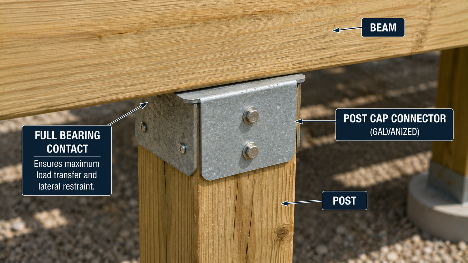
⭐⭐⭐⭐⭐ Deck Post-to-Footing Connection
Posts must be mechanically connected to their footing, not simply set on top of concrete.
Post base connectors
Manufactured post base connectors are commonly set into wet concrete and hold the post off the concrete surface to reduce moisture contact.
Lateral restraint
Where posts bear on footings, lateral restraint must be provided by manufactured connectors or a minimum post embedment into surrounding soil or a concrete pier, per IRC guidance.
Questionable soils
Where expansive, compressible, shifting or other questionable soils are present, surrounding soil should not be relied on for lateral support, and a mechanical connector approach is preferred.
Ground contact considerations
Posts in ground contact require appropriate pressure treatment rated for ground contact use, distinct from above-ground treated lumber.
See the Deck Footing Size Chart for footing dimension reference.
⭐⭐⭐⭐⭐ Deck Post Spacing and Footing Size
Wider post spacing increases tributary area, which increases post reaction and can require a larger footing.
| Tributary Area | Footing at 1,500 psf Soil | Footing at 2,000 psf Soil | Footing at 3,000 psf Soil |
|---|---|---|---|
| 20 sq ft | 10″ dia. | 8″ dia. | 8″ dia. |
| 40 sq ft | 14″ dia. | 12″ dia. | 10″ dia. |
| 60 sq ft | 18″ dia. | 14″ dia. | 12″ dia. |
| 80 sq ft | 20″ dia. | 16″ dia. | 14″ dia. |
| 100 sq ft | 22″ dia. | 18″ dia. | 14″ dia. |
| 120 sq ft | 24″ dia. | 20″ dia. | 16″ dia. |
Wider post spacing increases the tributary area assigned to each post, which increases the vertical load (reaction) that post delivers to its footing, which in turn generally requires a larger footing at a given soil bearing capacity. The IRC treats footing sizing (R507.3) and post sizing (R507.4) as related but separate checks, both driven by tributary area.
⭐⭐⭐⭐⭐ Deck Post Spacing and Soil Bearing Capacity
Footing capacity depends on post reaction, footing area and soil bearing value together.
A wider post spacing that increases tributary area and post reaction can be accommodated with either a larger footing at the same soil bearing capacity, or a similarly sized footing on stronger soil. Where soil bearing capacity is unknown, many jurisdictions default to a conservative 1,500 psf assumption, which produces larger footings than stronger soils such as compacted sandy or gravel soils rated at 2,000 to 3,000 psf.
Do not assume a specific soil bearing value without verification. Some jurisdictions require a soil test or engineering evaluation before permitting anything other than the conservative default value. See the Soil Bearing Capacity Chart for additional reference values.
⭐⭐⭐⭐ Deck Post Spacing and Lateral Stability
Gravity-load post spacing alone does not establish adequate lateral stability.
Tall decks and sway
Taller freestanding decks are more susceptible to lateral sway under wind or use-generated lateral loads.
Post bracing
Diagonal bracing or similar lateral bracing elements are often used to control sway on taller or freestanding post-and-beam systems.
Beam connections
Properly restrained beam-to-post connections also contribute to overall lateral stability, not just gravity load transfer.
Ledger lateral-load connections
On attached decks, dedicated lateral-load connectors at the ledger are commonly required regardless of post spacing, since the ledger connection itself resists lateral separation from the structure.
Choosing tighter post spacing for gravity-load reasons does not automatically provide adequate lateral stability. Lateral bracing and connection requirements should be evaluated separately.
⭐⭐⭐⭐⭐ How to Determine Deck Post Spacing
A practical workflow rather than picking a distance from habit.
Establish overall dimensions, ledger or freestanding condition, and beam line locations.
Measure the distance from ledger or support to beam, and any joist overhang past the beam.
Identify the applicable live load, dead load, and ground snow load for the project location.
Confirm the actual species and grade to be used for the beam.
Choose a candidate beam size and ply count to evaluate against the span table.
Find the column matching joist span/cantilever and the row matching the target beam span.
Confirm the table cell gives an acceptable beam size for the desired post spacing, or adjust the beam size or spacing.
Use the confirmed post spacing and joist span to determine tributary area at each post.
Cross-reference tributary area and post height against the post height table.
Use tributary area and soil bearing capacity to size each footing.
Confirm full bearing, lateral restraint, and appropriate connectors at both ends of each post.
Confirm the specific IRC edition and any local amendments in effect for the project jurisdiction.
⭐⭐⭐⭐⭐ How Many Deck Posts Do I Need?
A conceptual estimate, not a structural-adequacy formula by itself.
For a straight beam of length L with maximum allowable support spacing s: number of spaces is approximately L divided by s. Total posts equals the number of spaces plus one.
This estimate must then be adjusted for beam cantilevers at each end, required end-post locations, beam splice locations landing on a post, additional beam lines in a multi-beam layout, and the overall framing geometry of the specific deck. It provides a starting point for layout, not a substitute for confirming the actual beam span table value and post checks described above.
⭐⭐⭐⭐⭐ Deck Post Spacing Worked Examples
These examples demonstrate the process using stated assumptions and the applicable reference table, not a code-compliance determination.
1. 12-foot joist span with a double beam
2. Same deck with a joist cantilever added
3. Comparing 6-foot vs 8-foot post spacing
4. Converting post spacing into tributary area and footing reaction
⭐⭐⭐⭐⭐ Common Deck Post Spacing Mistakes
Most spacing errors trace back to one of these misunderstandings.
❌ Assuming 8 feet is universal
Allowable spacing depends on beam size, species, joist span and load, not a fixed distance.
❌ Ignoring beam size
The beam span table, not intuition, determines maximum post spacing for a given beam.
❌ Ignoring lumber species
Species-specific tables produce different allowable spans at the same beam dimension.
❌ Ignoring joist span
Longer joist spans reduce allowable beam span at a fixed beam size.
❌ Ignoring joist cantilever
Cantilevered joists add load to the beam beyond the backspan alone.
❌ Ignoring snow load
Higher ground snow load values require a different, more conservative beam span table.
❌ Increasing spacing because a larger post is used
Post size affects post height capacity, not the beam’s allowable span between supports.
❌ Ignoring post height
Tall posts at large tributary areas can require a larger post size even if the beam span checks out.
❌ Ignoring footing capacity
Wider spacing increases tributary load per post, which the footing must also be sized to support.
❌ Using inadequate beam-to-post connection
Full bearing and lateral restraint are required at every post, not just resting the beam on top.
❌ Not accounting for beam cantilever
Beam overhang past an end post has its own separate limit from the backspan.
❌ Placing beam splices away from permitted supports
Splices in multi-ply beams belong over a post with full bearing, not at an unsupported point.
⭐⭐⭐⭐⭐ 2024 IRC Deck Post, Beam and Footing Requirements
The code framework keeps these subjects connected within Section R507 rather than one standalone post-spacing table.
| Section | Covers |
|---|---|
| R507.3 | Deck footings |
| Table R507.3.1 | Minimum footing sizing by tributary area and soil bearing capacity |
| R507.4 | Deck post height and size requirements based on tributary area |
| R507.5 | Deck beam spans, organized by species, joist span/cantilever and snow load |
| R507.5.1 / R507.5.2 | Beam bearing and beam-to-post connection requirements |
| R507.6 | Deck joists, including joist span and cantilever limits |
These sections work together: joist span and cantilever (R507.6) determine the load a beam must carry, the beam span table (R507.5) sets maximum post spacing for a given beam, tributary area from that spacing feeds the post height table (R507.4) and footing table (R507.3.1), and R507.5.1/R507.5.2 govern how the beam actually connects to each post.
⭐⭐⭐⭐⭐ Deck Post Spacing Chart Limitations
Understanding what this chart does not establish is essential for structural safety.
No universal post spacing exists
Every value on this page depends on the specific beam, species, joist span and load combination.
Beam span controls support spacing
Post spacing is not an independent design choice; it equals the beam span for that section.
Species and grade matter
Southern Pine values do not transfer directly to Douglas Fir-Larch, Hem-Fir or Spruce-Pine-Fir.
Joist span and cantilever matter
Both increase beam load and reduce allowable beam span at a fixed beam size.
Snow and load conditions matter
Higher snow load or dead load assumptions require different, more conservative tables.
Post height and capacity matter
A beam span that checks out does not by itself confirm the post below it is adequate.
Footing size and soil matter
Post reaction from tributary area must still be matched to an adequately sized footing on suitable soil.
Lateral stability matters
Gravity-load spacing does not by itself establish adequate lateral bracing or connections.
Local code adoption and amendments can differ
Always verify the specific IRC edition and any local amendments enforced by the project’s jurisdiction.
Engineered beams and products require manufacturer data
LVL, PSL, steel or other engineered beams are not covered by these prescriptive sawn-lumber tables.
Frequently Asked Questions
📄 Download Deck Post Spacing Chart PDF
This PDF is a genuine field reference. Use the print button to create a print-ready or downloadable version.
Cite or Embed This Chart
Copy the page-wide citation to reference the complete Deck Post Spacing Chart.