Deck Load Chart 2026 – Dead, Live, Snow & Tributary Load
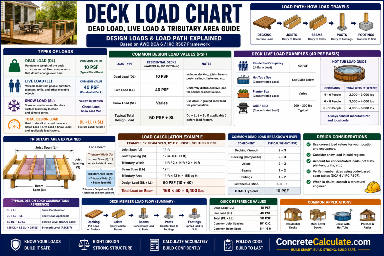
Deck Load Chart
Dead, Live, Snow & Tributary Load
Complete deck load reference for contractors and DIYers — how dead load, live load, snow load, and tributary area combine and travel through your deck’s structure.
 Reviewed by Muhammad Ramzan Babar, PhD Researcher (Plasma Physics) & Calculator Developer — View Profile
Important: Reference and Educational Guide Only
This page explains deck load concepts and illustrates common prescriptive design assumptions such as AWC’s DCA 6 (40 psf live + 10 psf dead), but it is not a substitute for your governing building code, ASCE 7 where applicable, local amendments, or an engineer’s design. Always verify the actual design load basis required for your project before construction.
⭐ Master Deck Load Chart
The main reference table — every deck load component, its type, and where it travels structurally.
Reference Values, Not Universal Design Loads
This page is deliberately not built around a single number like “40 psf = deck load.” Instead, it explains dead load, live load, snow load, and tributary load as distinct concepts that combine differently depending on your governing code — see the Load by Building Code section below for why this matters.
| Deck Component / Load | Load Type | Typical Design Consideration | Where Load Goes |
|---|---|---|---|
| Decking | Dead Load | Material weight per sq ft | Joists |
| Joists | Dead Load | Self-weight of framing member | Beam/Ledger |
| People | Live Load | Occupancy, commonly 40 psf basis | Joists |
| Furniture | Live Load | Occupancy, included in general live load basis | Joists |
| Snow | Environmental Load | Site-dependent, varies by region | Framing (joists/beams) |
| Hot Tub | Concentrated Load | Project-specific, outside standard prescriptive scope | Supporting structure (requires engineering) |
| Railings | Dead + Concentrated | Construction-dependent, separate guard/handrail loads | Joists/Framing at attachment points |
⭐ Deck Dead Load Chart
Dead load is the permanent weight that remains on the deck — it never leaves and doesn’t change over time.
| Component | Contributes To Dead Load |
|---|---|
| Deck Boards | Weight of the decking material itself, varies significantly by material |
| Joists | Self-weight of the framing lumber supporting the decking |
| Beams | Self-weight of the built-up or engineered beam members |
| Posts | Self-weight of vertical support members |
| Railings | Permanent weight of the guard system |
| Stairs | Self-weight of stringers, treads, and risers |
| Fasteners | Small but real contribution from bolts, screws, and connectors |
| Exterior Finishes | Paint, stain, or sealant add negligible but technically present weight |
| Roofing (if applicable) | Significant additional dead load for covered/roofed decks |
| Built-In Structures | Benches, planters, or other permanently attached features |
A common prescriptive assumption (such as AWC’s DCA 6) uses roughly 10 psf for dead load, intended to cover typical wood framing with wood or composite decking — heavier materials like stone pavers or concrete tile push well past this assumption and require separate accounting.
⭐ Deck Live Load Chart
Live load is the variable, temporary load that comes and goes with use.
| Live Load Source | Character |
|---|---|
| People | Occupants standing, sitting, or moving across the deck surface |
| Patio Furniture | Tables, chairs, loungers — anticipated within typical live load assumptions |
| Movable Equipment | Grills, portable heaters, and similar movable items |
| General Occupancy | The overall combined effect of typical residential deck use |
Live Load Depends on the Governing Code
For AWC’s DCA 6 prescriptive residential deck guide, structural members are sized primarily around a 40 psf live load plus 10 psf dead load. This basis explicitly anticipates occupants and typical lightweight furniture — it does not anticipate heavy planters, portable pools, hot tub water weight, or other loads beyond ordinary residential use. Never assume this number applies to every project or every code.
⭐ Deck Load by Building Code
A very important section — different governing standards specify meaningfully different design loads.
| Standard/Source | Typical Design Basis | Notes |
|---|---|---|
| IRC-Based Residential Deck Guidance | 40 psf live load, 10 psf dead load (common basis) | Basis used in many prescriptive residential deck span tables |
| ASCE 7-Based Structural Design | Can require 100 psf for certain occupancy classifications | Applies where ASCE 7’s occupancy category governs rather than IRC prescriptive tables |
| Local Building Codes | Varies | Local jurisdictions can adopt different code editions or requirements |
| Local Amendments | Varies | Can modify, restrict, or add to the base code’s deck provisions |
Why This Distinction Matters
AWC itself directly addresses this: its DCA 6 guide states that ASCE 7 requires 100 psf for certain applications, while the IRC-based residential deck provisions that DCA 6 supports are based on a 40 psf live load and 10 psf dead load. These are two different design bases for two different scopes — never copy a single load number from an online chart without first confirming which standard actually governs your specific project and occupancy classification.
⭐ Deck Load per Square Foot Chart
A clear reference distinguishing what’s a fixed reference value versus what depends entirely on project conditions.
| Load Category | psf | Notes |
|---|---|---|
| Dead Load | Varies (commonly ~10 psf reference) | Depends on actual construction and materials used |
| Live Load | Code-dependent (commonly 40 psf reference) | Depends on occupancy classification and governing standard |
| Snow Load | Site-dependent | Varies significantly by climate and location |
| Total Design Load | Calculated (not a fixed number) | Depends on the applicable load combination for your project |
There is deliberately no single “total deck load” number in this table — total design load is always the result of a calculation specific to your governing code, occupancy, and site conditions, not a value you can read off a generic chart.
⭐ Deck Load Calculation Chart
The fundamental relationship behind every load calculation on this page.
The Basic Formula
Area × Load = Total Load. Multiply a given area (the whole deck, a tributary area, or a specific component’s footprint) by the applicable load in pounds per square foot to get the total force that area contributes. That total load then transfers through the structure: Deck Area → Total Load → Joists → Beam → Posts → Footings → Soil. Each step redistributes that load into a smaller number of increasingly concentrated points.
⭐ Deck Tributary Area Chart
One of the main backlink-worthy assets on this page — the single most important concept for understanding deck loads.
| Concept | Explanation |
|---|---|
| What Tributary Area Means | The portion of deck surface whose load funnels into a specific structural member |
| How Tributary Width Is Determined | Roughly half the joist span on each side of a beam, or the full joist span for edge conditions |
| How Joists Transfer Load | Each joist carries the load from its own spacing width, delivering it to its end supports |
| How Beams Receive Tributary Load | A beam collects load from all joists framing into it along its length |
| How Posts Receive Beam Reactions | Each post receives the beam’s reaction based on its tributary length along that beam |
| How Footings Transfer Load to Soil | The footing spreads the post’s concentrated load over enough area to stay within the soil’s bearing capacity |
⭐ Deck Load Path Diagram
Likely the strongest visual asset on the page — the complete journey of every pound of load on a deck.
⭐ Deck Joist Load Chart
How the total deck load distributes among individual joists.
| Factor | Effect on Joist Load |
|---|---|
| Joist Spacing | Wider spacing increases the tributary width (and load) each joist must carry |
| Tributary Width | Roughly equal to the joist spacing, since each joist carries the strip of decking centered on it |
| Joist Span | Longer span increases the total load the joist and its supports must handle |
| Distributed Load | The standard uniform live/dead load spread evenly along the joist length |
| Concentrated Load | Point loads (like a single heavy object) that don’t spread evenly and may require separate checking |
For matching joist size to your actual span and spacing, see our full Deck Joist Span Chart.
⭐ Deck Beam Load Chart
How joist loads accumulate into the beam that supports them.
| Concept | Explanation |
|---|---|
| Beam Tributary Area | The deck area (roughly half the joist span, times beam length) feeding load into that beam |
| Uniform Load | Standard distributed load along the beam’s length from its tributary strip |
| Point Load | A concentrated load from a single post-supported feature transferring directly onto the beam |
| Beam Reactions | The forces the beam transfers into each of its supporting posts |
| Beam Span | Distance between posts, which determines how much of the tributary load reaches each reaction point |
AWC’s DCA 6 methodology sizes deck beams based on the tributary load delivered by joists framing into them — for full beam sizing tables, see our Deck Beam Span Chart.
⭐ Deck Post Load Chart
How load accumulates at posts, and why interior posts often carry more than corner posts.
| Tributary Area | Approximate Load Character | Post Location |
|---|---|---|
| Smallest (quarter tributary from two directions) | Lowest post load | Corner Posts |
| Moderate (half tributary from one direction, full from adjacent) | Moderate post load | Edge Posts |
| Largest (full tributary from multiple adjacent bays) | Highest post load | Interior Posts |
Why Interior Posts Carry More
A corner post typically only picks up tributary area from two adjacent framing bays meeting at that corner, while an interior post positioned along a continuous multi-span beam can receive tributary area contributions from beam segments on both sides — effectively doubling its share compared to an end condition.
⭐ Deck Footing Load Chart
The final step in the load path — converting a post’s concentrated load into a footing size that soil can support.
The Relationship
Post Load → Required Bearing Area → Footing Size. Divide the post’s total load (in pounds) by the soil’s allowable bearing capacity (in pounds per square foot) to get the minimum required footing area in square feet. Convert that area to a practical round diameter or square footing size. For the full tributary-area-to-footing-size relationship with worked reference tables, see our Deck Footing Size Chart.
Deck Load by Deck Size
Illustrating the area-to-load relationship without assigning a fixed universal load to each dimension.
| Deck Size | Area | Illustrative Note |
|---|---|---|
| 8 × 10 | 80 sq ft | Total load = Area × assumed design load; framing layout determines individual member loads |
| 10 × 12 | 120 sq ft | Same principle — total load scales with area, but distribution depends on layout |
| 12 × 12 | 144 sq ft | Beam/post placement determines how this total load concentrates at each support |
| 12 × 16 | 192 sq ft | Larger area increases total load, but per-member load depends on tributary geometry |
| 14 × 16 | 224 sq ft | Framing plan, not raw area, ultimately sets individual member requirements |
| 16 × 20 | 320 sq ft | Often benefits from an intermediate beam to manage the larger total load |
| 20 × 20 | 400 sq ft | Significant total load; framing layout is critical to distributing it safely |
Area Alone Doesn’t Set Component Loads
Total deck load scales with area (Area × assumed design load = Total Load), but how that load distributes to individual joists, beams, posts, and footings depends entirely on the framing layout — not the raw square footage.
Deck Load by Joist Spacing
How spacing changes the tributary width and load carried by each joist.
| Spacing | Tributary Width per Joist | Effect on Load per Joist |
|---|---|---|
| 12″ O.C. | Narrowest | Lowest load per joist, more joists total |
| 16″ O.C. | Standard | Moderate load per joist, most common default |
| 19.2″ O.C. | Slightly wider | Slightly higher load per joist |
| 24″ O.C. | Widest | Highest load per joist, fewer joists total |
Deck Load by Beam Configuration
Beam placement changes how the total deck load distributes across the structure.
| Configuration | Effect on Load Distribution |
|---|---|
| Single Beam | All non-ledger-supported load concentrates on one beam line |
| Two-Beam Configuration | Splits joist span and load between two separate support lines |
| Beam at Midspan | Divides total joist span roughly in half, reducing load per joist segment |
| Beam Near House | Creates a short backspan and potentially a longer cantilever, shifting load distribution |
| Beam at Outside Edge | Joists span the full distance from ledger to beam with no intermediate support |
Deck Load for Attached vs Freestanding Decks
Comparing the load paths and additional considerations for each configuration.
| Factor | Attached Deck | Freestanding Deck |
|---|---|---|
| Load Path | Ledger → House Connection, and Joists → Beam → Posts → Footings | Beam(s) → Posts → Footings (fully independent) |
| Lateral Stability | Partially relies on ledger connection to house | Must achieve full lateral stability independently |
| Design Consideration | Ledger fastening and flashing become critical load-path elements | Bracing and footing/post system must resist lateral loads alone |
⭐ Deck Snow Load Chart
Deliberately no single nationwide snow number — snow requirements vary dramatically by location.
| Factor | Consideration |
|---|---|
| Ground Snow Load | Baseline regional value that varies widely across climate zones |
| Roof/Deck Snow Considerations | Roofed decks accumulate snow differently than open decks |
| Local Climate | Mountain, northern, and high-elevation regions carry substantially higher snow loads |
| Snow Accumulation | Depth and density both affect the actual load, not just presence of snow |
| Drifting | Wind-driven snow can pile disproportionately in certain areas of a deck |
| Sliding Snow | Snow sliding off an adjacent roof onto a deck can add concentrated, unexpected load |
No Universal Snow Load Number
Snow load requirements vary significantly by location, elevation, and structure exposure. AWC’s guidance notes that for a deck not prone to sliding or drifting snow, common prescriptive criteria can sometimes be conservatively applied using a uniformly distributed snow load comparable to the standard live load basis — but this depends entirely on your specific site conditions and should never be assumed without confirming your local ground snow load and any drifting/sliding exposure.
⭐ Deck Wind Load & Lateral Load
Conventional residential decks must address lateral loads separately from vertical bearing.
| Consideration | Explanation |
|---|---|
| Wind Pressure | Lateral force from wind acting on the deck and any attached structures like railings or roofs |
| Lateral Deck Movement | Side-to-side racking motion that must be resisted by bracing or connections |
| Connection Requirements | Tension ties and hold-down hardware help resist lateral forces, particularly at the ledger |
| Bracing | Diagonal or knee bracing resists lateral movement, especially for freestanding or elevated decks |
| Ledger Attachment | Vertical and lateral load transfer to the house must both be addressed at this connection |
| Post Stability | Taller posts need additional consideration for buckling and lateral resistance |
AWC’s DCA 6 incorporates an approved lateral-load resistance approach under its own stated conditions — but this is a distinct design check from vertical load sizing and must be verified separately for your specific deck configuration.
Equipment for Your Project
Affiliate disclosure: As an Amazon Associate, ConcreteCalculate earns from qualifying purchases. We may also earn a commission from other affiliate links at no additional cost to you.
⭐ Deck Railing Load
A dedicated section — railing loads behave differently from ordinary uniformly distributed floor loads.
| Load Type | Character |
|---|---|
| Guard Loads | Concentrated lateral load applied at the top of the guard, distinct from the deck’s floor live load |
| Handrail Loads | Separate concentrated load requirement specific to handrail components on stairs |
| Concentrated Loads | Railings must resist point loads applied at specific locations, not just distributed pressure |
| Post Connections | Guard post attachment to the framing must transfer these concentrated forces effectively |
| Attachment to Framing | The joist or rim board receiving the guard post must be adequately sized for this additional demand |
Don’t Simply Add Railing Load to Floor psf
Railing guard and handrail loads are specific concentrated forces applied at defined locations (like the top of the guard), not an addition to the deck’s general uniform floor live load. These require their own separate check at the post connection and supporting framing.
Deck Stair Load Chart
Stairs introduce additional load paths beyond the main deck structure.
| Element | Load Consideration |
|---|---|
| Stair Dead Load | Self-weight of stringers, treads, risers, and any stair railings |
| Stair Live Load | Occupancy load from people using the stairs, following the same general basis as the deck |
| Stair Stringers | Primary structural members carrying stair loads to their supports |
| Landing Loads | Intermediate or bottom landings need their own bearing/support consideration |
| Concentrated Loads | Stair use creates repeated, localized loading distinct from a flat deck surface |
⚠️ Deck Hot Tub Load Chart
A high-value dedicated section — hot tubs are explicitly excluded from standard prescriptive deck load assumptions.
| Load Component | Consideration |
|---|---|
| Empty Tub Weight | Significant dead load even before filling with water |
| Water Weight | Adds substantial additional weight, often the largest single load component |
| Occupants | Multiple bathers add concentrated live load within the tub’s footprint |
| Concentrated Loading | Total weight concentrates in a small footprint rather than spreading evenly like typical furniture |
| Location of Tub | Placement affects which joists, beams, and posts bear the concentrated load |
| Supporting Joists | Often require closer spacing or larger sizing specific to the tub footprint |
| Beam/Post Reactions | Significantly higher than typical residential occupancy loads at these locations |
| Footing Requirements | Frequently require larger, dedicated footings or pads under the tub area |
Hot Tubs Are Outside Standard Prescriptive Scope
AWC specifically identifies concentrated loads such as hot tubs as outside the scope of its DCA 6 prescriptive approach, and recommends a design professional or another approved installation approach for these situations. A hot tub’s combined weight of tub, water, and occupants can total several thousand pounds concentrated in a small footprint — this cannot be handled by simply “adding” it to a standard 40 psf/10 psf calculation. Always use an engineered design for any hot tub deck.
Deck Roof Load Chart
Standard deck span tables should not automatically be applied to a roof-supported deck.
| Additional Load | Consideration |
|---|---|
| Roof Dead Load | Self-weight of roof framing and roofing materials transferred through posts |
| Roof Live Load | Maintenance/construction access loads specific to roof structures |
| Snow Load | Roof-specific snow accumulation, potentially different from open-deck assumptions |
| Wind Load | Uplift and lateral forces on the roof structure requiring separate resistance |
| Ceiling Load | Finished ceiling materials add dead load if the underside is finished |
Ordinary residential deck span tables built around a 40 psf/10 psf basis do not account for these additional roof-related loads — a roofed deck typically needs separate verification or engineered design.
Deck Load for Different Decking Materials
Material density directly affects dead load contribution.
| Material | Relative Dead Load Contribution |
|---|---|
| Pressure-Treated Wood | Common baseline assumption in many prescriptive tables |
| Cedar | Generally lighter than pressure-treated pine, similar order of magnitude |
| Composite | Often heavier per square foot than solid wood decking |
| PVC | Generally lighter than composite, but varies by product |
| Hardwood (e.g., tropical species) | Often significantly denser and heavier than standard framing lumber |
Deck Load for Different Framing Materials
Self-weight varies by framing material and affects the overall dead-load calculation.
| Material | Relative Self-Weight |
|---|---|
| Dimensional Lumber | Standard baseline assumption for most prescriptive tables |
| Engineered Lumber (LVL, etc.) | Similar or slightly higher density than sawn lumber, varies by product |
| Steel Framing | Significantly heavier per member than wood, but often smaller cross-sections used |
| Aluminum Framing | Lighter than steel, sometimes used for reduced dead load in specific systems |
⭐ Deck Load and Deflection
The difference between strength and serviceability — a critical distinction for bouncy decks.
Strength vs Serviceability
A member can be strong enough to never break under load, yet still bend (deflect) more than feels acceptable underfoot. This is why deflection is checked separately from raw bending strength. AWC’s deck joist guidance commonly uses an L/360 simple-span deflection criterion under its stated DCA 6 assumptions — meaning maximum deflection is limited to the span length divided by 360. This applies to joist deflection, beam deflection, and requires separate consideration for cantilevered sections, which can deflect differently than simple spans.
Deck Load and Beam Span
Higher tributary load reduces how far a given beam can safely span.
The Relationship
Higher tributary load → greater beam demand → potentially shorter allowable beam span for a given beam size. This is why beam span tables are organized around joist span (which sets tributary load) rather than beam size alone. See our full Deck Beam Span Chart.
Deck Load and Joist Span
Longer joist spans deliver more tributary load to the beams supporting them.
The Relationship
Longer joist span → greater load carried by supporting beams, since each joist collects load over a longer distance before delivering it to its end supports. See our full Deck Joist Span Chart.
Deck Load and Footing Size
Completing the internal-linking chain from load through to soil bearing.
The Relationship
Higher post reaction → greater required soil-bearing area, since the footing must spread that specific load without exceeding the soil’s allowable bearing capacity. This completes the full chain: Deck Load → Joist → Beam → Post → Footing. See our full Deck Footing Size Chart.
⭐ Deck Load Combinations
Educational overview of how different load types combine — not a universal structural design equation.
| Combination | General Concept |
|---|---|
| Dead + Live | The most common baseline combination for typical residential deck occupancy design |
| Dead + Snow | Relevant where snow load may govern over standard live load in a given region |
| Wind + Dead | Relevant for lateral load and stability checks, particularly for elevated or exposed decks |
| Concentrated Loads | Checked separately and added where applicable (hot tub, heavy equipment), not simply blended into uniform psf |
| Other Applicable Combinations | Determined by the governing code’s specific load combination requirements for your structure |
⭐ Visual Deck Load Guide
Original engineering diagrams designed to earn backlinks — far more useful than generic decorative graphics.
⭐ How to Calculate Deck Load
A complete workflow, not a single blind formula.
Determine Deck Area
Calculate the total surface area of the deck being designed.
Identify Applicable Dead Load
Confirm the actual construction’s dead load, not just a generic assumption.
Identify Applicable Live Load
Confirm which code/standard governs and its required live load value.
Check Snow Requirements
Confirm your local ground snow load and any drifting/sliding exposure.
Identify Concentrated Loads
Flag any hot tubs, heavy equipment, or other loads outside standard uniform assumptions.
Determine Tributary Areas
Establish the tributary area for each joist, beam segment, and post.
Determine Joist Loads
Calculate the load each joist must carry based on its tributary width and span.
Determine Beam Loads
Sum the joist loads feeding into each beam segment.
Determine Post Reactions
Calculate the load transferred to each post based on its position along the beam.
Check Footing Requirements
Convert post loads into required footing area based on soil bearing capacity.
Check Lateral Loads and Connections
Verify bracing, ledger connections, and hold-down hardware address wind and lateral forces.
How to Read a Deck Load Chart
Making this page accessible to homeowners while still useful to contractors.
| Term | Meaning |
|---|---|
| psf | Pounds per square foot — the standard unit for distributed structural loads |
| Pounds | Total force, used for point loads and reactions at specific locations |
| Tributary Area | The specific portion of deck area whose load reaches a given structural member |
| Uniform Load | Load spread evenly across an area or length |
| Point Load | Load concentrated at a single specific location |
| Dead Load | Permanent, unchanging structural weight |
| Live Load | Variable, temporary occupancy load |
| Design Load | The total combined load a member is designed to safely carry |
⭐ Deck Load Calculation Examples
Realistic worked examples tracing load from the deck surface down to the footing.
Small Residential Deck
12 × 16 Deck
Tributary Load on a Beam
Post Reaction
Footing Load
Common Deck Load Calculation Mistakes
Avoiding these errors prevents structural failures and unsafe assumptions.
Using Deck Area Alone to Size Every Component
Total area doesn’t determine individual member loads — tributary area and layout do.
Treating Dead Load and Live Load as the Same Thing
These are fundamentally different load types with different design implications.
Ignoring Snow
Assuming a snow-free load basis in a region with significant snowfall can seriously undersize the structure.
Ignoring Concentrated Loads
Hot tubs, heavy planters, and similar items don’t fit standard uniform load assumptions.
Ignoring Tributary Area
Failing to account for how load actually distributes leads to incorrect member sizing.
Using the Wrong Code’s Live Load
Applying an IRC-based 40 psf assumption where ASCE 7’s 100 psf governs (or vice versa) misrepresents the actual requirement.
Assuming a Hot Tub Is an Ordinary Live Load
Concentrated hot tub loads require engineered design, not standard prescriptive tables.
Ignoring Railing Loads
Guard and handrail loads are separate concentrated requirements, not part of the general floor psf.
Ignoring Lateral Loads
Vertical load capacity alone doesn’t address wind and racking forces on the structure.
Using Beam Tables Without Checking Their Assumptions
Applying a table’s span value without confirming its species, grade, and load basis overstates actual capacity.
Assuming Deeper Footings Automatically Compensate for Insufficient Footing Area
Depth addresses frost protection and bearing stratum access — not undersized bearing area.
Frequently Asked Questions
📄 Download Deck Load Chart PDF
Get a printable field reference including dead-load reference, live-load reference, snow-load guidance, tributary-area diagram, load-path diagram, joist load guide, beam load guide, post reaction guide, footing load guide, worked examples, and a contractor quick-reference sheet.