Pipe Bend Radius Chart: Steel, HDPE, PEX & Copper
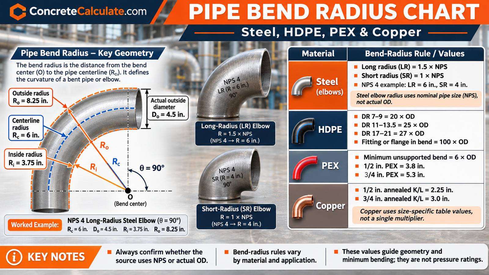
Steel elbow radii, HDPE, PEX, and copper minimum bends, bend geometry formulas, and clearance guidance for U.S. piping and plumbing work.
 Reviewed by Muhammad Ramzan Babar, PhD Researcher (Plasma Physics) & Calculator Developer. View Profile
A pipe bend radius chart gives the centerline radius of standard steel elbows (1.5 × NPS long radius, 1 × NPS short radius) and the minimum cold-bend radii for HDPE, PEX, and copper. These values come from different standards, so never apply one multiplier across materials.
Pipe Bend Radius Chart
Steel Long-Radius Elbows
A standard long-radius steel butt-weld elbow has a centerline radius of 1.5 × NPS, so an NPS 4 elbow has a 6 in. radius and an NPS 12 elbow has an 18 in. radius.
| Nominal pipe size (NPS) | Actual steel pipe OD (in.) | Long-radius elbow centerline radius (in.) | Short-radius elbow centerline radius (in.) |
|---|---|---|---|
| 1 in. | 1.315 in. | 1.50 in. | 1.00 in. |
| 1¼ in. | 1.660 in. | 1.88 in. | 1.25 in. |
| 1½ in. | 1.900 in. | 2.25 in. | 1.50 in. |
| 2 in. | 2.375 in. | 3.00 in. | 2.00 in. |
| 2½ in. | 2.875 in. | 3.75 in. | 2.50 in. |
| 3 in. | 3.500 in. | 4.50 in. | 3.00 in. |
| 4 in. | 4.500 in. | 6.00 in. | 4.00 in. |
| 6 in. | 6.625 in. | 9.00 in. | 6.00 in. |
| 8 in. | 8.625 in. | 12.00 in. | 8.00 in. |
| 10 in. | 10.750 in. | 15.00 in. | 10.00 in. |
| 12 in. | 12.750 in. | 18.00 in. | 12.00 in. |
Sources: ASME B16.9-2024 dimensional conventions (long radius 1.5 × NPS, short radius 1 × NPS), corroborated by published industry fitting tables. OD values are standard inch-series steel pipe outside diameters. Values rounded to two decimals (NPS 1¼ long radius is 1.875 in. exactly).
Fitting geometry, not a field-bending limit
These figures describe standard manufactured elbow geometry. They are not the minimum permissible cold-bending radius of straight steel pipe, and they must not be applied to HDPE, PEX, copper, PVC, CPVC, or electrical conduit. Actual dimensions and tolerances follow the specified fitting standard and product.
Small-size note: NPS ½ and ¾ are special cases. The cited long-radius tables list a 1.50 in. center-to-end dimension for both sizes, not 1.5 times their numerical NPS (0.75 in. and 1.125 in.). Verify the manufacturer’s fitting geometry before extending the simplified formula to those sizes.
Steel Short-Radius Elbows
A standard short-radius elbow has a centerline radius of 1 × NPS and is made as a 90° fitting only. The industry fitting tables reviewed list short-radius elbows from NPS 1 through NPS 24, so confirm availability for the size you need. The chart above shows both radii side by side.
HDPE, PEX and Copper Reference Values
Flexible pipe and tubing are governed by minimum cold-bend rules from their own industry publications, not by the steel elbow convention.
| Pipe or tubing | Governing relationship | Measured as | Detailed table |
|---|---|---|---|
| Steel butt-weld elbow, long radius | 1.5 × NPS | Fitting centerline radius | Section 5 |
| Steel butt-weld elbow, short radius | 1 × NPS | Fitting centerline radius | Section 5 |
| HDPE / PE pipe | 20 × OD to 27 × OD by DR group; 100 × OD with a fitting or flange in the bend | Minimum cold field-bending radius | Section 10 |
| PEX plumbing tubing | 6 × actual OD unless the manufacturer specifies otherwise | Minimum free (unsupported) cold bend | Section 12 |
| Copper water tube | Size, type, and temper specific values | Minimum radius for mechanical bending equipment | Section 14 |
| Field-bent steel pipe | Design and process dependent | No universal minimum | Section 8 |
| PVC, CPVC, conduit | No universal radius; use fittings or manufacturer guidance | Product specific | Section 15 |
These rules come from different standards and publications and must not be combined into one universal multiplier.
How to Interpret Different Sources
Check three things before using any radius: what the number is measured to (centerline, inside, or outside), what it is multiplied by (NPS or actual OD), and whether it describes a manufactured fitting or a minimum field bend. For NPS versus actual OD values, see the pipe outside diameter chart.
What Is Pipe Bend Radius?
Pipe bend radius is the radius of the circular arc a pipe follows through a bend, normally measured from the bend center to the pipe centerline, in inches for U.S. work.
Centerline Radius
The centerline radius (Rc) runs from the bend center to the middle of the pipe cross-section. It is the value used for standard elbows, bend tables, and most flexible-pipe rules.
Inside Radius
The inside radius (Ri) runs from the bend center to the inner wall of the curve. It equals Rc minus half the outside diameter, and it is the tight side of the bend.
Outside Radius
The outside radius (Ro) runs from the bend center to the outer wall of the curve. It equals Rc plus half the outside diameter and sets the space the bend occupies.
Bend Angle
The bend angle (θ) is the angle the pipe turns through, such as 22.5°, 45°, or 90°. The radius and the angle together fix the arc length and the setback of the bend.
How Is Pipe Bend Radius Measured?
Pipe bend radius is measured from the bend center to the pipe centerline unless a document states otherwise, so Ri and Ro must be converted before comparing them with a published value.
Centerline Measurement
Standard elbows and the PPI, PPFA, and CDA tables in this chart refer to a radius that locates the pipe’s centerline path. PPI’s PEX guide, for example, measures the free bending radius at the mid-point of the bend.
Bend Center
All three radii start at the same bend center. A radius drawn from a different point is not a valid Ri, Rc, or Ro.
Actual Outside Diameter
Do is the real measured or specified OD, not the nominal size. For plastic and copper rules that use a multiple of OD, use the actual OD from the product table.
Measuring an Existing Bend
- Measure the actual OD of the pipe at the bend.
- Measure the inside or outside radius of the curve with a radius gauge or a template.
- Convert to centerline radius: Rc = Ri + Do/2, or Rc = Ro – Do/2.
- Compare Rc with the source table that applies to that material.
Pipe Bend Radius vs. Nominal Pipe Size
Nominal pipe size (NPS) is a designation, not the actual outside diameter: NPS 4 steel pipe has a 4.500 in. OD, and the conventional radius of an NPS 4 long-radius elbow is 6 in., not 6.75 in.
NPS vs. OD
NPS 2 pipe measures 2.375 in. OD, NPS 4 measures 4.500 in., and NPS 6 measures 6.625 in. Full conversions are on the pipe outside diameter chart.
Why NPS 4 Is Not 4-in. OD
NPS is a legacy size designation. From NPS 14 upward the OD in inches equals the NPS, but below that the OD is larger than the number.
Diameter Conventions
The ASME B16.9 elbow radius uses the numerical NPS: R = 1.5 × NPS for long radius. HDPE and PEX rules use actual OD: R = k × OD. Mixing the two conventions is one of the most common errors. For inside diameters, see the pipe inside diameter chart.
Long radius: RLR = 1.5 × 4 = 6 in.
Short radius: RSR = 1 × 4 = 4 in.
Not: 1.5 × 4.5 = 6.75 in.
Interpretation: 6 in. is the centerline radius of the manufactured fitting. It is not the minimum safe cold-bending radius of a straight 4 in. steel pipe.
Long-Radius vs. Short-Radius Elbows
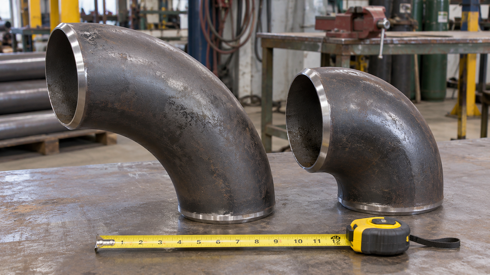
A long-radius elbow has a 1.5 × NPS centerline radius and a short-radius elbow has a 1 × NPS radius, so the long-radius fitting needs 50 percent more radius for the same nominal size.
| Feature | Long radius (LR) | Short radius (SR) |
|---|---|---|
| Centerline radius | 1.5 × NPS | 1 × NPS |
| NPS 4 example | 6.00 in. | 4.00 in. |
| Fitting angles tabulated | 90°, 45°, 180° returns | 90° only |
| Space needed | More | Less, tighter turn |
| Typical use | General piping, lower flow disturbance | Tight spaces where the tighter turn is acceptable |
Sources: ASME B16.9-2024 and industry fitting tables.
Centerline Dimensions
For the same NPS, the long-radius centerline sweeps wider by 0.5 × NPS. On NPS 4, that is 2 in.
Space and Clearance
The short-radius elbow fits where space is tight, but both fittings need weld preparation clearance and room for insulation. See bend clearance.
Flow Considerations
A tighter turn generally disturbs flow more than a gentler one. Hydraulic detail belongs on the pipe flow rate chart, and a short summary is in Section 18.
Application Restrictions
Check the project specification before substituting short-radius for long-radius fittings. Piping specifications often restrict short-radius use.
ASME B16.9 Steel Pipe Elbow Dimensions
ASME B16.9-2024 covers factory-made wrought butt-welding fittings from NPS ½ through NPS 48, with standard center-to-end dimensions for 90° elbows, 45° elbows, and 180° returns.
90° Elbows
For a 90° elbow, the center-to-end dimension equals the centerline radius, so the long-radius values in the main chart double as procurement dimensions: NPS 4 is 6.00 in., NPS 6 is 9.00 in.
45° Elbows
The 45° center-to-end dimension is not R times tan 22.5° in every size. The published values, especially in small sizes, are tabulated separately.
| NPS | Centerline radius R (in.) | Theoretical tangent distance R tan 22.5° (in.) | Catalog 45° center-to-end B (in.) | B (mm) |
|---|---|---|---|---|
| 1 in. | 1.50 | 0.62 | 0.88 | 22 |
| 1¼ in. | 1.88 | 0.78 | 1.00 | 25 |
| 1½ in. | 2.25 | 0.93 | 1.12 | 29 |
| 2 in. | 3.00 | 1.24 | 1.38 | 35 |
| 2½ in. | 3.75 | 1.55 | 1.75 | 44 |
| 3 in. | 4.50 | 1.86 | 2.00 | 51 |
| 4 in. | 6.00 | 2.49 | 2.50 | 64 |
| 6 in. | 9.00 | 3.73 | 3.75 | 95 |
Catalog values are from published industry fitting tables that follow ASME B16.9 (rounded to two decimals in inches). Verify against the standard or the manufacturer for procurement. Theoretical values are calculated.
For NPS 2, the catalog dimension is 1.38 in. while 3 × tan 22.5° is 1.24 in. These are different conventions, so use the fitting table for layout, not the arc formula.
180° Returns
A long-radius 180° return has a center-to-center dimension of twice the radius. Published values include 3.00 in. for NPS ½, ¾, and 1, and 12.00 in. for NPS 4. Confirm other sizes in the standard.
Center-to-End Dimensions
Center-to-end is measured from the theoretical intersection of the end centerlines to the weld end face. It is the dimension used for spool layout and takeoff.
1D, 1.5D, 3D and 5D Pipe Bends
A “1.5D” bend has a centerline radius of 1.5 times the pipe’s nominal diameter, and 1D, 3D, and 5D follow the same pattern; they describe geometry, not a universal minimum.
Meaning of D
For standard fittings, D means the nominal pipe size in inches. For specified fabricated or induction bends, D is defined by the project specification, so read the definition.
| Designation | Radius | NPS 4 example (in.) | Context |
|---|---|---|---|
| 1D | 1 × NPS | 4.00 | Short-radius elbow |
| 1.5D | 1.5 × NPS | 6.00 | Long-radius elbow |
| 3D | 3 × NPS | 12.00 | 3D elbow listed in industry fitting tables; also used as a specified bend radius |
| 5D | 5 × NPS | 20.00 (calculated) | Specified bend radius, project dependent |
3D and 5D are not automatically minimum bend requirements for steel pipe. NPS 4 values for 3D and 5D are calculated from the definition.
Standard Fittings vs. Fabricated Bends
A standard fitting follows a published table. A fabricated bend follows the project’s design code and bending procedure, and the radius is part of that design.
Steel Pipe Minimum Bend Radius
There is no single minimum bend radius for all field-bent steel pipe, because the allowable radius depends on the piping code, the wall thickness, the bending process, and the service.
Manufactured Fittings vs. Field Bends
A 1.5D radius belongs to a factory elbow. A field bend must meet the design code, and no free source reviewed justifies one numeric table for every steel pressure pipe.
Cold Bending
Cold bending is done with benders and tooling matched to the pipe size and wall. Results depend on the equipment and the material grade.
Hot and Induction Bending
Hot or induction bending heats a short zone of the pipe and forms it to a specified radius, followed by controlled cooling and any heat treatment the code requires.
Wall Thinning and Ovality
The outer wall thins and the cross-section can flatten. See the pipe wall thickness chart for wall values and Section 16.
Code-Specific Requirements
For process piping, ASME B31.3 paragraph 332 requires that thickness after bending not be less than the design requires and that the finished surface be free of cracks and substantially free of buckling. Flattening, the difference between maximum and minimum diameters at any cross-section, is limited to 8 percent of nominal OD for internal pressure and 3 percent for external pressure. The edition and project specification govern. Source: U.S. DOE piping-code comparison report quoting B31.3 para. 332.
Do not use a universal 3D or 5D rule
Confirm the radius, bending method, inspection, and heat treatment with the engineer of record.
Stainless Steel Pipe Bending
Stainless steel butt-weld elbows made to ASME B16.9 follow the same 1.5 × NPS and 1 × NPS conventions as carbon steel, but field-bending capability depends on the grade, wall thickness, equipment, and process.
Tube/Pipe Grade
Different grades work-harden and spring back differently, so a tool setup for one grade is not automatically right for another.
Wall Thickness
Thin walls wrinkle and flatten more easily and often need internal support such as a mandrel.
Bending Equipment
Rotary-draw benders with matched tooling are common for stainless tube. See bending methods.
Process Requirements
Sanitary, pharmaceutical, and pressure services can add inspection and cleanliness requirements. Follow the applicable specification, not a generic radius.
HDPE Pipe Bend Radius Chart
PPI’s municipal water field manual gives a minimum cold bend radius of 20 × OD for DR 7 to 9, 25 × OD for DR 11 to 13.5, 27 × OD for DR 17 to 21, and 100 × OD where a fitting or flange sits in the bend.
| HDPE dimension ratio (DR) | Minimum cold bend radius | Example radius, actual OD = 4.50 in. (in.) | Example radius (ft) |
|---|---|---|---|
| DR 7 to 9 | 20 × OD | 90.0 in. | 7.50 ft |
| DR 11 to 13.5 | 25 × OD | 112.5 in. | 9.38 ft |
| DR 17 to 21 | 27 × OD | 121.5 in. | 10.12 ft |
| Fitting or flange within the bend (any DR) | 100 × OD | 450.0 in. | 37.50 ft |
Multipliers: PPI Polyethylene Piping Systems Field Manual for Municipal Water Applications, Table 6 (2009 edition, municipal water, open-cut trench). The last two columns are calculated for a hypothetical 4.50 in. OD pipe, not a catalog size. Thinner-wall DR values above 21 appear in other PPI publications with larger multipliers, so match the document to your application.
Actual OD
The multiplier applies to the actual outside diameter in inches, not the nominal pipe size. See HDPE pipe dimensions and dimension ratios for OD values by size.
DR/SDR
Dimension ratio changes the multiplier because wall thickness changes the pipe’s stiffness. Section 11 explains the relationship.
PPI 20×, 25× and 27× Values
The three multipliers are not interchangeable. Use the row for your DR group and keep the PPI document name and edition with the number.
Fitting and Flange Effects
Fittings and flanges are rigid compared with the pipe, so PPI sets the minimum radius at 100 × OD when one is in the bend, and limits the radius to 100 × OD for about five pipe diameters on either side of the fitting. See the pipe flange size chart for flange dimensions.
Underground Installation
The table is for open-cut trench installation: the trench is excavated to the bend radius and the pipe string is swept into it. Temporary restraints may be needed, and the pipe can spring back forcibly if restraints slip, so plan the safety precautions before bending.
R = 25 × 4.50 = 112.5 in.
In feet: 112.5 ÷ 12 = 9.375 ft = 9 ft 4.5 in.
How HDPE Dimension Ratio Affects Bend Radius
HDPE dimension ratio (DR) is the average outside diameter divided by the minimum wall thickness, and a higher DR means a thinner wall and a larger bend multiplier.
Definition of DR
DR = OD ÷ t, where OD is the outside diameter (in.) and t is the minimum wall thickness (in.).
Wall Thickness
For a 4.50 in. OD pipe, minimum wall thickness is OD ÷ DR. Full OD and wall tables belong on the HDPE pipe dimensions and dimension ratios.
| DR | Min. wall t = 4.50 ÷ DR (in.) | PPI Table 6 multiplier |
|---|---|---|
| 7 | 0.643 | 20 × OD |
| 9 | 0.500 | 20 × OD |
| 11 | 0.409 | 25 × OD |
| 13.5 | 0.333 | 25 × OD |
| 17 | 0.265 | 27 × OD |
| 21 | 0.214 | 27 × OD |
Wall thickness is calculated from the DR definition for a hypothetical OD. Multipliers from the PPI municipal water field manual, Table 6.
Diameter Calculation
Always multiply by the actual OD of the product. A change from IPS to DIPS sizing changes the OD and the resulting radius.
Application-Dependent Limitations
Do not call the table universal. It covers PE pipe in a municipal-water open-cut trench; other PPI documents list different groupings, including DR 15.5, for particular applications. Keep the source and application context with the number.
PEX Pipe Bend Radius Chart
PEX plumbing tubing needs a free (unsupported) cold bend radius of at least 6 × its actual outside diameter, unless the manufacturer specifies otherwise, which is 5.3 in. for 3/4 in. PEX.
| Nominal PEX size | Actual tubing OD (in.) | Minimum bend radius, published (in.) | Against-coil radius, 3 × published (in.) |
|---|---|---|---|
| 3/8 in. | 0.500 in. | 3.0 in. | 9.0 in. |
| 1/2 in. | 0.625 in. | 3.8 in. | 11.4 in. |
| 3/4 in. | 0.875 in. | 5.3 in. | 15.9 in. |
| 1 in. | 1.125 in. | 6.8 in. | 20.4 in. |
| 1¼ in. | 1.375 in. | 8.3 in. | 24.9 in. |
| 1½ in. | 1.625 in. | 9.8 in. | 29.4 in. |
| 2 in. | 2.125 in. | 12.8 in. | 38.4 in. |
Source: PPI/PPFA PEX Plumbing Design and Installation Guide, Third Edition (April 2026), Table 9.1 (6 × OD bend radius). Values are rounded to one decimal by the source. The last column is calculated from the guide’s statement that certain coiled tubing bent against the coil needs three times the table value. The guide lists larger sizes too.
6×OD Reference
The bend radius is based on actual tubing OD, not nominal size, and is measured at the mid-point of the bend. For 3/4 in. PEX: R = 6 × 0.875 = 5.25 in., published as 5.3 in. Use the published value rather than rounding down. Nominal and actual sizes are on the PEX tubing nominal and actual sizes.
Common Nominal Sizes
Residential supply and branch lines are mostly 3/8 in. to 1 in. tubing. Larger sizes are used for mains and manifolds.
Manufacturer Exceptions
PPI’s 6 × OD value applies unless the manufacturer specifies otherwise. For example, one manufacturer’s design guide lists a 5 × OD minimum cold bend for its tubing (REHAU PEX design guide), so always check the product literature. PPI also gives 8 × OD for PEX water service lines.
Against-Coil Bending
For certain coiled PEX, bending against the coil direction requires three times the table value. For 1/2 in. tubing, that is 3.8 × 3 = 11.4 in.
R = 6 × 0.875 = 5.25 in.
PEX Bend Supports and Coil-Direction Limits
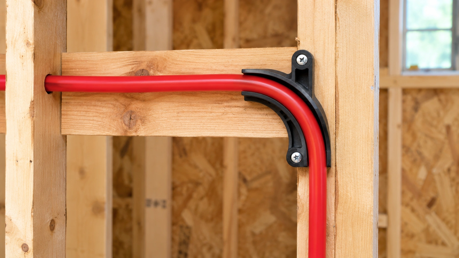
PEX bend supports, elbows, and manufacturer-approved fittings are the way to turn a tight corner when the free 6 × OD radius does not fit.
Free Bending
Free bending relies on the tube’s own stiffness and the 6 × OD radius from the PPI table above.
Bend-Support Devices
Bend supports hold the tube to a smaller radius where the product is approved for it. The allowed radius comes from the manufacturer, not from the 6 × OD rule.
Tight Spaces
If the available space is smaller than the radius, use an elbow fitting or a smaller tube size rather than forcing the bend.
Kink Avoidance
Do not bend tubing tighter than allowed, and do not bend against the coil without checking the product. A kinked section must be handled per the manufacturer’s repair procedure.
Manufacturer-Approved Repairs
Use only repair methods approved for the product and system. Check local plumbing code and the product listing.
Copper Pipe Bend Radius Chart
CDA lists minimum copper tube bend radii from 3/4 in. for 1/4 in. annealed tube up to 9 in. for 1¼ in. annealed tube, and states they apply to mechanical bending equipment only.
| Nominal copper tube size | Tube type | Temper | Minimum bend radius (in.) | Tube OD, nominal + 1/8 in. (in.) | Radius ÷ OD (calculated) |
|---|---|---|---|---|---|
| 1/4 in. | K, L | Annealed | 3/4 in. | 0.375 in. | 2.0 |
| 3/8 in. | K, L | Annealed | 1½ in. | 0.500 in. | 3.0 |
| 3/8 in. | K, L, M | Drawn | 1¾ in. | 0.500 in. | 3.5 |
| 1/2 in. | K, L | Annealed | 2¼ in. | 0.625 in. | 3.6 |
| 1/2 in. | K, L, M | Drawn | 2½ in. | 0.625 in. | 4.0 |
| 3/4 in. | K, L | Annealed | 3 in. | 0.875 in. | 3.4 |
| 3/4 in. | K, L | Drawn | 3 in. | 0.875 in. | 3.4 |
| 1 in. | K, L | Annealed | 4 in. | 1.125 in. | 3.6 |
| 1¼ in. | K, L | Annealed | 9 in. | 1.375 in. | 6.5 |
Source: CDA Copper Tube Handbook, Table 4.1 (CDA Table 4.1). Radii are minimums for mechanical bending equipment only. The OD and ratio columns are informational calculations; the ratio varies from about 2.0 to 6.5, so no single multiplier applies to copper.
Type K
Type K has the thickest wall of the common water tubes and appears in the annealed and drawn rows above.
Type L
Type L is the common building-water tube and shares the K and L rows in Table 4.1.
Type M
Type M appears in the table only for drawn 3/8 in. and 1/2 in. tube. Check the manufacturer and code before bending thin-wall tube.
Annealed vs. Drawn
Annealed (soft) copper forms more readily than drawn (hard) tube. Both can be bent with the proper bender, but the minimum radius depends on tube size and temper. Tube sizes and wall thickness are on the copper pipe size chart.
Mechanical Bending Limitations
The proper bender size must be used for each tube size. A manufactured copper elbow follows a fitting dimension, not the on-site bend radius in this table. Never apply the PEX 6 × OD rule to copper.
PVC and CPVC Bending Limitations
Rigid PVC and CPVC pipe has no universal cold bend radius; manufacturers instruct installers to make changes of direction with fittings and not to bend rigid pipe with an external heat source.
Rigid Pipe Versus Flexible Tubing
Rigid solvent-weld pipe is straight stock designed for factory elbows. Flexible plastic tubing, such as PEX, is a different product with its own table.
Manufacturer-Approved Methods
Charlotte Pipe’s safety information states that using an external heat source to bend ABS, CPVC, or PVC may result in structural damage to pipe and fittings and that changes in direction should be made with fittings (Charlotte Pipe Important Safety Information).
Factory Elbows
Use listed elbows. They keep the pressure rating and fit the pipe size. Size references: PVC pipe size chart, CPVC pipe size chart, and ABS pipe size chart.
Heating and Temperature Concerns
Do not use open flame or uncontrolled heating on plastic pipe. Heat can thin the wall, discolor the plastic, and reduce the pipe’s strength.
Solvent-Welded Fittings
Do not bend or pull pipe into position after it is solvent welded, and do not install fittings under stress.
Product-specific example, not a universal rule
Some CPVC copper-tube-size products publish their own limits. One manufacturer states that 1/2 in. and 3/4 in. FlowGuard Gold and ReUze pipe should not be bent tighter than 18 in., and 1 in. pipe not tighter than 24 in. Always use the radius from the product you are installing.
Electrical conduit bend radius is set by the electrical code and the conduit type, and is outside this chart.
How Wall Thickness Affects Pipe Bending
Wall thickness affects bending because the outer wall thins and the cross-section can flatten, and schedule alone does not determine a bend radius.
| Material | Wall descriptor | Effect on bending |
|---|---|---|
| Steel pipe | Schedule or specified wall thickness | Thinner walls wrinkle and flatten more easily |
| HDPE | Dimension ratio (DR) | Higher DR means a thinner wall and a larger multiplier |
| Copper tube | Type K, L, or M | Table 4.1 lists radius by size, type, and temper |
Descriptors are summarized from the sources in this chart. For actual wall values see the pages linked below.
Pressure Pipe
Pressure pipe has a design thickness that must still be met after bending.
Schedule
For schedule dimensions, see the pipe schedule chart, the Schedule 40 Pipe Chart, and the Schedule 80 Pipe Chart. Steel pipe weights are on the steel pipe weight chart.
SDR
For plastic pipe, SDR and DR describe diameter-to-wall ratio. A thin wall is more prone to ovalizing and kinking.
Strain and Deformation
Bending stretches the outer wall and compresses the inner wall. The tighter the radius, the greater the strain.
Why Schedule Alone Is Not Enough
Two pipes with the same schedule but different diameters bend differently. The radius, material, process, and code all matter. See the pipe wall thickness chart.
Bend Radius, Pressure Rating and Pipe Deformation
A bend radius alone does not prove that a bent pipe still meets its pressure rating or dimensional requirements.
Wall Thinning
The outside of a bend thins. Steel process piping must still meet the required thickness after bending.
Ovality
Flattening reduces the cross-section. B31.3 limits flattening to 8 percent of nominal OD for internal pressure and 3 percent for external pressure.
Fitting Ratings
A manufactured elbow carries its own rating from the standard and product. Do not assume a field bend has the same rating. See the pipe pressure rating chart.
Bending-Process Qualification
Field-fabricated steel bends need a qualified procedure under the governing code.
Inspection
Check for cracks, buckling, ovality, and thickness at the bend. See quality checks.
Pipe Bend Radius and Flow Loss
A larger bend radius generally lowers directional flow loss, but it is not a universal pressure-loss guarantee, and detailed hydraulics belong on the pipe flow rate chart.
Directional Losses
Fluid changing direction loses energy. Minor loss is often written hL = K × v² ÷ (2g), where K is the minor-loss coefficient, v is velocity, and g is gravitational acceleration.
Smooth Bends vs. Elbows
Smooth, long-radius bends usually produce a lower K than tight elbows, but K depends on size, Reynolds number, and roughness.
Reynolds Number
Flow regime changes loss behavior, so published K values apply to defined conditions.
Why a Larger Radius Is Not a Guarantee
Fittings, flanges, and extra pipe length also add loss, so compare the whole route. Pipe volume for the bend length can be found with the pipe volume chart.
Pipe Bend Radius Formulas
Pipe bend radius formulas fall into five groups: multiples of diameter, standard elbow conventions, inside and outside radii, arc length and tangent geometry, and curvature.
Multiples of Diameter
R = k × Do
Variables: R is the minimum centerline bend radius (in.), k is the source-defined multiplier, Do is the actual outside diameter (in.).
PEX: 6 × 0.875 = 5.25 in. HDPE: 25 × 4.50 = 112.5 in.
Standard Elbow Conventions
RLR = 1.5 × NPS and RSR = 1 × NPS
Variables: NPS is the numerical nominal pipe size in inches, not the actual OD.
RLR = 1.5 × 6 = 9 in. RSR = 6 in.
Do not apply these to field bending. Check the ASME table for small sizes.
Inside and Outside Radius
Ri = Rc – Do/2 and Ro = Rc + Do/2
Ri = 6 – 4.5/2 = 3.75 in. Ro = 6 + 4.5/2 = 8.25 in.
These are ideal geometric envelopes, not fitting wall profiles, tolerances, or installation clearances.
Curvature
κ = 1 / R
Variables: κ is centerline curvature (1/in.), R is centerline radius (in.).
κ = 1/6 = 0.167 per in. κ = 1/4 = 0.250 per in.
Curvature is geometry only. It is not an allowable strain or a material strength value.
How to Calculate Pipe Bend Arc Length
Pipe bend arc length equals π × R × θ ÷ 180, so a 90° bend with a 6 in. centerline radius has an arc length of 9.425 in.
Centerline Arc Length
The arc length follows the centerline, which is the path used for cut-length and developed-length estimates.
Degree-to-Radian Conversion
Radians = degrees × π ÷ 180. Use the degree form of the formula directly to avoid unit errors.
Larc = π R θ / 180
Variables: Larc is arc length (in.), R is centerline radius (in.), θ is the bend angle in degrees. In radians, Larc = R θ.
Larc = (π)(6)(90) / 180 = 3π = 9.425 in.
Larc = (π)(6)(45) / 180 = 4.712 in.
This is the idealized centerline arc length, not the straight end-to-end dimension of the fitting.
| Bend angle θ | Centerline arc length Larc | Tangent distance T |
|---|---|---|
| 22.5° | 0.3927 R | 0.1989 R |
| 30° | 0.5236 R | 0.2679 R |
| 45° | 0.7854 R | 0.4142 R |
| 60° | 1.0472 R | 0.5774 R |
| 90° | 1.5708 R | 1.0000 R |
| 180° | 3.1416 R | Not applicable (tangents are parallel) |
Calculated geometry for a circular centerline bend, rounded to four decimals. Arc length = π R θ / 180 (θ in degrees); T = R tan(θ/2).
How to Calculate Pipe Bend Setback and Tangent Length
The tangent distance of a circular bend is T = R × tan(θ/2), which equals 2.485 in. for a 45° bend with a 6 in. radius.
Theoretical Intersection
The two straight centerlines meet at a point V. The arc starts and ends at the tangent points a distance T from V.
Tangent Length
T is used to set out a bend from the intersection point. The angle table in Section 20 lists T ÷ R for common angles.
T = R tan(θ/2)
Variables: T is the distance from each tangent point to the theoretical tangent intersection (in.), R is centerline radius (in.), θ is the bend angle.
T = 6 × tan(22.5°) = 6 × 0.4142 = 2.485 in.
T = 6 × tan(45°) = 6.000 in.
This is a theoretical tangent distance. It does not automatically replace the center-to-end dimension of an ASME catalog elbow.
45° and 90° Geometry
For a 90° bend, T equals R, so the tangent distance of a 6 in. radius is 6 in. and matches the 90° elbow center-to-end value. For 45°, T is 0.4142 R.
Manufactured Fitting Center-to-End Dimensions
The catalog 45° center-to-end dimension can differ from the theoretical value, especially in small sizes (NPS 2: 1.38 in. catalog versus 1.24 in. theoretical). Use the table in Section 6 for procurement and layout.
Pipe Bend Clearance and Installation Space
Bend clearance must include more than the centerline radius, because the outside envelope is Rc + Do/2 before insulation, supports, and access are added.
| Elbow | Centerline Rc (in.) | Inside Ri (in.) | Outside Ro (in.) | Ro with 1 in. insulation (in.) |
|---|---|---|---|---|
| Long radius | 6.00 | 3.75 | 8.25 | 9.25 |
| Short radius | 4.00 | 1.75 | 6.25 | 7.25 |
Calculated from Ri = Rc – Do/2 and Ro = Rc + Do/2. The 1 in. insulation column is a hypothetical allowance. Real clearance also depends on weld bevel, tolerances, supports, and access.
Inside Envelope
The inside radius sets the tightest space the bend leaves open. A very small inside radius can interfere with adjacent pipe or structure.
Outside Envelope
The outside radius sets how far the bend extends into the room or trench. Use it to check the chase, sleeve, or wall opening.
Adjacent Pipes
Parallel pipes that turn together need different radii so that their envelopes do not collide. Check supports and hangers near the bend with the pipe support spacing chart.
Wall Penetration
Allow room for sleeves and seals around the pipe at the outside envelope.
Insulation and Fittings
Add insulation thickness and check flanges, valves, and couplings near the bend. For flange dimensions see the pipe flange size chart.
Pipe Bending Methods and Equipment
Pipe bending methods range from hand benders for soft copper to induction bending for steel pipe, and each method has its own radius and quality limits.
| Method | Typical use | Key point |
|---|---|---|
| Hand benders | Small copper tube | Use a bender sized for the tube; the CDA Handbook calls for the proper size of bender for each tube size |
| Rotary-draw bending | Tube and small pipe | Wraps the pipe around a die; tooling is matched to the size |
| Mandrel bending | Thin-wall or tight bends | Internal support limits wrinkling and flattening |
| Roll bending | Large-radius gentle curves | Forms broad curves by passing pipe through rolls |
| Induction bending | Steel pipe to a specified radius | Localized heating and controlled cooling under a qualified procedure |
| Field cold bending | HDPE, PEX, soft copper | Use the minimum radii and manufacturer limits in this chart |
General descriptions of common methods. Equipment limits and procedures come from the tool manufacturer and the governing code.
The goal here is selection, not operation. Use the bender and procedure documented for the pipe size, wall, and material.
Pipe Bend Defects and Quality Checks
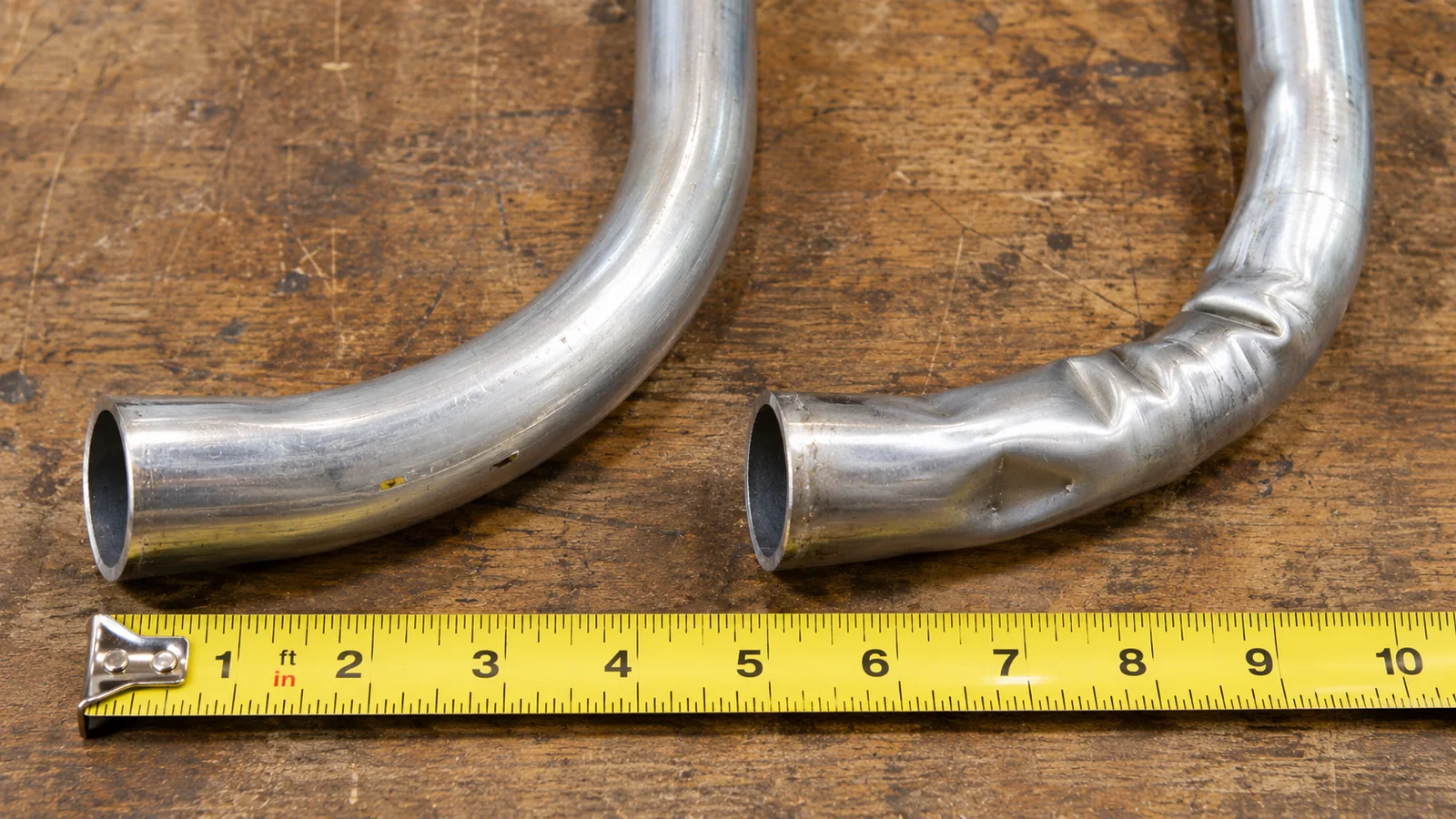
The main pipe bend defects are kinking, wrinkling, ovality, wall thinning, cracking, and springback, and a specified radius does not prove that the bend is acceptable.
| Defect | What it looks like | Common cause | Check |
|---|---|---|---|
| Kinking | Sharp collapse of the wall | Radius too small or no support | Visual and bore check; reject kinked pipe |
| Wrinkling | Ripples on the inside of the bend | Compression on the inner wall | Visual inspection |
| Ovality | Round section flattens to an oval | Thin wall or no internal support | Measure max and min diameters; B31.3 flattening limit is 8% (internal pressure) or 3% (external pressure) of nominal OD |
| Wall thinning | Outer wall gets thinner | Tight radius, stretching | Measure thickness against the design minimum |
| Cracking | Surface cracks | Overbending, wrong temper or temperature | Visual and any required NDE |
| Springback | Bend opens after release | Elastic recovery | Measure the bend angle; plastics can spring back forcibly |
Steel limits from ASME B31.3 paragraph 332.2.1. Other materials follow the manufacturer and the applicable standard.
Inspection
Inspect every bend for round cross-section, smooth surface, and required thickness before the pipe goes into service. A defective bend is cut out and replaced.
How to Choose the Correct Pipe Bend Radius
Choose the pipe bend radius in six checks: identify the material, the actual OD, the wall or DR, the bend type, the governing source, and the available space.
- Identify the material. Steel, HDPE, PEX, copper, or rigid plastic.
- Identify the actual OD. Use the product table, not the nominal size.
- Check wall thickness, DR, type, or temper.
- Identify the bend type. Factory elbow, fabricated bend, or field cold bend.
- Verify the source requirement. Standard, manufacturer, or specification.
- Check the surrounding space. Include insulation, supports, and access.
| Material and bend type | Use this source | Based on |
|---|---|---|
| Steel butt-weld elbow | ASME B16.9-2024 | NPS convention |
| Field-fabricated steel bend | Governing piping code (such as ASME B31.3), project specification | Design and process |
| HDPE / PE pipe | PPI Polyethylene Piping Systems Field Manual, Table 6 | Actual OD and DR |
| PEX tubing | PPI/PPFA PEX Guide, Table 9.1, or manufacturer | Actual OD |
| Copper tube | CDA Table 4.1 | Size, type, temper |
| PVC, CPVC | Manufacturer instructions; use fittings | Product specific |
Common Pipe Bend Radius Mistakes
The most common pipe bend radius mistakes come from applying one rule to the wrong material or mixing which radius is being measured.
Using one multiplier for every material
A single k value cannot cover steel, plastic, and copper.
Using actual OD for an ASME elbow radius
Standard elbow radius uses NPS: 1.5 × 4 = 6 in., not 1.5 × 4.5.
Treating 1.5D as a field-bending minimum
1.5D describes a factory elbow, not every steel bend.
Mixing centerline, inside, and outside radius
Convert before comparing with a published value.
Using the PEX 6×OD rule for copper
Copper follows CDA Table 4.1 by size, type, and temper.
Ignoring fittings in HDPE bends
A fitting or flange in the bend raises the minimum to 100 × OD.
Heating PVC or CPVC with open flame
Manufacturers warn that external heat can damage pipe and fittings.
Treating tangent distance as the catalog dimension
Use the ASME center-to-end table for a 45° fitting.
Pipe Bend Radius FAQs
What is pipe bend radius?
Pipe bend radius is the radius of the arc a pipe follows through a bend, normally measured from the bend center to the pipe centerline. The inside radius is the centerline radius minus half the outside diameter, and the outside radius is the centerline radius plus half the outside diameter. Always confirm which radius a table uses.
What is the difference between 1D and 1.5D bends?
A 1D bend has a centerline radius equal to the nominal pipe size, as in a short-radius elbow, while a 1.5D bend has a radius of 1.5 times the nominal size, as in a long-radius elbow. For NPS 4, that is 4 in. versus 6 in. Both describe fitting geometry, not a minimum bend limit for straight pipe.
What is the bend radius of an NPS 4 long-radius elbow?
A standard NPS 4 long-radius 90° butt-weld elbow has a 6 in. centerline radius, which is 1.5 times 4. The short-radius version has 4 in. The actual pipe OD is 4.500 in., but the ASME convention uses the nominal size, not the OD, so the radius is not 6.75 in.
How do you calculate pipe bend radius?
Use the rule for the material. For standard steel elbows, multiply NPS by 1.5 or 1. For PEX or HDPE, multiply the actual outside diameter by the source multiplier, such as 6 for PEX or 25 for HDPE DR 11. Copper uses the CDA table by size, type, and temper. Do not mix methods.
What is the minimum bend radius for HDPE?
In the PPI municipal water field manual, the minimum cold bend radius for PE pipe in an open-cut trench is 20 times OD for DR 7 to 9, 25 times OD for DR 11 to 13.5, and 27 times OD for DR 17 to 21. With a fitting or flange in the bend, it is 100 times OD.
What is the minimum bend radius for PEX?
PPI and PPFA give 6 times the actual tubing OD for free, unsupported PEX bends unless the manufacturer specifies otherwise. For 1/2 in. PEX that is 3.8 in., and for 3/4 in. it is 5.3 in. Some coiled tubing bent against the coil needs three times those values. Always check the product instructions.
How is copper tube bend radius determined?
Copper bend radius is not a single multiple of diameter. The CDA Copper Tube Handbook lists minimum radii for mechanical bending equipment by nominal size, tube type, and temper, such as 2¼ in. for 1/2 in. annealed K or L tube and 4 in. for 1 in. annealed tube. Use a bender sized for the tube.
Is pipe bend radius measured from the inside or the centerline?
Published bend radius values are normally centerline radii, measured from the bend center to the middle of the pipe. If you measure the inside curve, add half the outside diameter to get the centerline radius. If you measure the outside curve, subtract half the outside diameter. Make sure the source defines its radius the same way.
Is nominal pipe size equal to actual outside diameter?
No. Nominal pipe size is a designation. NPS 2 steel pipe has a 2.375 in. OD, NPS 4 has 4.500 in., and NPS 6 has 6.625 in. Only from NPS 14 upward does the OD in inches equal the NPS. Always use the product table when a rule needs the actual OD.
Can I bend PVC or CPVC pipe?
Manufacturers of PVC and CPVC advise making direction changes with fittings and warn that using an external heat source to bend the pipe may cause structural damage. No universal cold bend radius applies. Use listed elbows for pressure plumbing, and follow the specific product instructions for any flexible plastic tubing.
Is a 3D or 5D bend the minimum for steel pipe?
No. 3D and 5D describe radii as multiples of nominal diameter and are used for some fittings and specified fabricated or induction bends. They are not universal minimums for field-bent steel pipe, which depends on the design code, wall, bending process, and inspection. Follow the project specification and ASME B31.3 where it applies.
Does a tighter bend always mean more pressure loss?
Generally a tighter bend has a higher minor-loss coefficient, but the result depends on pipe size, Reynolds number, roughness, and the fittings in the route. A larger radius is not a guaranteed pressure-loss reduction. Use the pipe flow rate chart for flow calculations and manufacturer data for specific fittings.
Using the Pipe Bend Radius Chart Correctly
This pipe bend radius chart separates three different measurements: the centerline radius of standard manufactured steel elbows (1.5 × NPS and 1 × NPS), the minimum cold-bend radius of flexible pipe and tubing (PPI for HDPE and PEX, CDA for copper), and the design- and process-dependent radius of field-fabricated steel bends. Identify the material, use the actual OD where the source requires it, and confirm the governing standard, manufacturer instructions, and local code before bending or ordering. Pair it with the pipe outside diameter chart, the HDPE pipe dimensions and dimension ratios, and the pipe flow rate chart for related dimensions and flow checks.
Authoritative References
| Source | Provision | Used for |
|---|---|---|
| ASME B16.9-2024 | Factory-made wrought butt-welding fittings | Long-radius and short-radius elbow geometry |
| PPI Polyethylene Piping Systems Field Manual for Municipal Water Applications | Table 6 (2009 edition, municipal water) | HDPE minimum cold bend radius by DR |
| PPI/PPFA PEX Plumbing Design and Installation Guide, Third Edition (April 2026) | Table 9.1 (April 2026, third edition) | PEX 6 × OD bend radius and against-coil rule |
| CDA Copper Tube Handbook | Table 4.1 | Copper tube mechanical bending radii |
| ASME B31.3 Process Piping | Paragraph 332 | Bending quality and flattening limits (as quoted in a DOE comparison report) |
| Charlotte Pipe Important Safety Information | Installation and safety guidance | PVC and CPVC direction changes |
Verify the current edition of each document before relying on a value. Product-specific manufacturer instructions override general tables.
Download Pipe Bend Radius Chart PDF
Use your browser print function to save this page as a PDF for jobsite binders and estimating folders. Buttons and image placeholders are hidden in the print layout.
- Steel elbow radius chart
- HDPE, PEX, and copper bend tables
- Bend angle and tangent reference
- Formulas and worked examples
- Quick source guide