
Concrete Control Joint Layout Guide: Patterns & Spacing
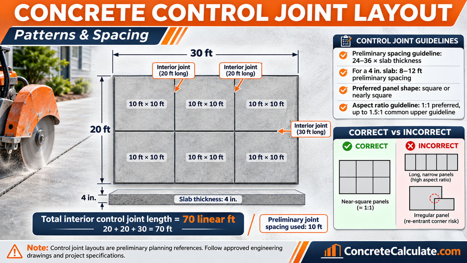
This concrete control joint layout guide turns slab dimensions into a plan. Measure the slab, mark walls, columns, and corners, pick a spacing of 24 to 36 times thickness, divide into near-square panels, and verify the layout against approved plans before marking. A 4 in. slab starts near 10 ft.
How to Lay Out Concrete Control Joints in 6 Steps
A joint layout works best as a short repeatable method. Start with the slab’s dimensions, then divide it into near-square panels that respect corners, openings, and restraints.
- Measure the slab and identify its thickness.
- Identify walls, columns, corners, openings, and construction joints.
- Estimate a preliminary maximum panel spacing using the appropriate guidance.
- Divide the slab into square or nearly square panels.
- Align joints with corners, openings, and other restraints without creating awkward panels.
- Check and mark the final layout against the approved plans before placement or cutting.
Quick Rule: Preliminary Spacing
Variables: S is the preliminary maximum spacing in feet, t is slab thickness in inches, and k is a planning multiplier, typically between 24 and 36, subject to the slab design. NRMCA also suggests a general upper limit near 15 ft.
Starting point: about 10 ft is a common starting spacing for an ordinary 4 in. slab, though the final layout may use smaller panels for better proportions.
| Step | Action | Required information | Output | Caution |
|---|---|---|---|---|
| 1 | Measure the slab | Length, width, thickness | Dimensioned slab outline | Measure the formed size, not the planned size |
| 2 | Mark constraints | Walls, corners, openings, columns | Restraint map | Missed restraints cause awkward cracking paths |
| 3 | Select preliminary spacing | Slab thickness, specifications | Initial panel interval | A starting value, not a code requirement |
| 4 | Divide into panels | Slab geometry | Proposed joint grid | Use whole numbers of panels |
| 5 | Check geometry | Panel lengths and widths | Aspect ratio and spacing validation | Check both spacing and shape |
| 6 | Verify and mark | Plans, embedded items, field measurements | Approved field layout | Engineered plans take precedence |
Table 1. Six-step joint layout planning workflow. Results are preliminary planning outputs, not approved construction details.
What Is a Concrete Control Joint Layout?
A control joint layout is the plan-view arrangement of contraction joints that divides a slab into panels. It shows where each joint runs, which direction it takes, how big each panel is, and how the lines relate to isolation and construction joints.
A layout drawing is different from a saw-cut detail. The layout answers where the joints go, while the detail specifies depth, blade, and cutting method.
For definitions, joint types, and broader depth and timing background, see the Concrete Control Joints guide. This guide stays on layout decisions.
Why Joint Layout Matters for Concrete Cracking
Concrete shrinks as it dries and changes size with temperature. When the slab is restrained by subgrade friction, walls, or reinforcement, that movement builds tension, and concrete is weak in tension.
A contraction joint is a planned weakened plane that encourages cracking along a chosen line. NRMCA states that cracks cannot be prevented entirely but can be controlled and minimized by properly designed joints, and ACI notes that some random cracking should be expected even with good joint spacing.
A poor layout can still crack in the wrong places. Long narrow panels, L-shaped panels, and joints that miss a re-entrant corner can leave random diagonal cracks, and uneven panels are harder to maintain. See why concrete cracks for causes beyond layout.
What to Check Before Drawing a Joint Layout
A short survey prevents most redraws. Gather these items before placing a single line.
- Slab length and width
- Thickness and any thickness changes
- Construction drawings and specifications
- Reinforcement and embedded components
- Columns, walls, pits, drains, and openings
- Existing concrete interfaces
- Expected traffic and loading
- Construction placement sequence
- Curing and environmental conditions
An existing engineered joint plan takes precedence over any general spacing rule. ACI 302.1R-15 states the joint layout and details should be provided by the designer, and that spacing is the designer’s responsibility. For thickness background, see the Concrete Slab Thickness Chart.
Control Joints vs Isolation Joints vs Construction Joints
These three joint types appear on a layout plan with different purposes, and they must be drawn and marked differently.
Contraction or control joints
These lie within the slab and influence where shrinkage cracks form.
Isolation joints
Isolation joints separate the slab from walls, columns, footings, and other restraining elements so each can move independently.
Construction joints
Construction joints sit at planned or unavoidable boundaries between concrete placements.
| Joint type | Function | Common plan location | Example legend |
|---|---|---|---|
| Contraction | Guides shrinkage cracking | Within slab panels | CJ |
| Isolation | Separates restraining objects | Walls, columns, fixed structures | IJ |
| Construction | Boundary between placements | Planned pour boundary | CONST |
| Engineered movement joint | Allows specified movement | Project-defined locations | EJ, where specified |
Table 2. Joint types and layout symbols. The symbols are illustrative and not universal industry standards. The actual project legend governs.
How to Calculate Preliminary Control Joint Spacing
The commonly cited planning range is 24 to 36 times the slab thickness, expressed in feet when thickness is in inches. NRMCA CIP 6 gives this range and adds a general upper limit of about 15 ft.
Calculation: 4 in. Slab
With k = 24: S = 24 × 4 ÷ 12 = 8 ft.
With k = 36: S = 36 × 4 ÷ 12 = 12 ft.
For a 5 in. slab: the same math gives 10 to 15 ft, so the 15 ft limit applies at the top of the range.
Treat 8 to 12 ft as a planning range, not a required minimum and maximum. Closer spacing can be a better choice, and an engineered plan overrides the rule.
For spacing by thickness in table form, see the Expansion Joint Spacing Chart. This guide does not repeat a large thickness chart.
How to Keep Concrete Panels Square or Nearly Square
Panel shape matters as much as spacing. The aspect ratio compares the longer panel side with the shorter one.
Formula: Panel Aspect Ratio
Example 1: a 10 × 10 ft panel has R = 10 ÷ 10 = 1.0.
Example 2: a 12 × 8 ft panel has R = 12 ÷ 8 = 1.5.
ACI 302.1R-15 prefers 1 to 1 and sets a maximum of 1.5 to 1 for unreinforced slabs, slabs reinforced only for shrinkage and temperature, and shrinkage-compensating concrete. NRMCA likewise says panel length should not exceed 1.5 times the width.
Meeting a spacing guideline and meeting an aspect-ratio guideline are separate checks, and a panel must satisfy both.
Why L-Shaped, T-Shaped, and Narrow Panels Are Problematic
Irregular panel shapes concentrate stress at inside corners and create unplanned cracking paths. ACI 302.1R-15 says L- and T-shaped panels should be avoided, and NRMCA says to avoid L-shaped panels.
A pattern can look evenly spaced and still create bad shapes. Three examples are common:
- A long narrow end strip left over after dividing by a fixed spacing
- An L-shaped panel formed around a house corner
- A staggered T-intersection where joint lines are offset
The incorrect half of the diagram in the next section shows a narrow strip, an offset, and uneven panels on the same slab size.
How to Draw a Joint Grid for a Rectangular Slab
For an ordinary rectangular slab, work out panel dimensions first and place joints second. This avoids the leftover strips that come from marking a joint at every nominal interval from one edge.
- Choose a preliminary spacing from slab thickness and site constraints.
- Divide each slab dimension into a whole number of panels.
- Calculate the actual panel lengths in both directions.
- Verify aspect ratios of every panel.
- Adjust the layout to remove short edge strips.
- Check alignment with columns and other features.
Changing the number of panels often gives a better layout than keeping the nominal spacing. A 30 ft side at a 12 ft target could become 12, 12, and 6 ft, but three 10 ft panels are more even.
A coordinated control-joint grid creates near-square panels and continuous joint lines, reducing avoidable layout-related cracking risks.
Worked Layout: A 20 × 30 ft Concrete Slab
This is the primary calculation example. The slab is 20 × 30 ft and 4 in. thick, with a preliminary spacing target of about 10 ft. It is an ordinary unreinforced slab-on-ground used for education.
Calculation: Panels and Interior Joint Length
Panels: divide 20 ft into two 10 ft panels and 30 ft into three 10 ft panels, giving six 10 × 10 ft panels with ratio 1.0.
Joint lines: one 30 ft line runs along the length at the 10 ft mark, and two 20 ft lines cross it at 10 and 20 ft.
Result: six square panels and 70 linear ft of interior joint lines.
| Example | Slab size | Thickness | Preliminary layout | Panel size | Interior joint length |
|---|---|---|---|---|---|
| Rectangular slab | 20 × 30 ft | 4 in. | 2 × 3 panels | 10 × 10 ft | 70 ft |
| Driveway | 12 × 30 ft | 4 in. | 1 × 3 panels | 12 × 10 ft | 24 ft |
| Patio | 12 × 16 ft | 4 in. | 2 × 2 panels | 6 × 8 ft | 28 ft |
| Garage | 20 × 22 ft | 5 in. | 2 × 2 panels | 10 × 11 ft | 42 ft |
| Walkway | 4 × 24 ft | 4 in. | 1 × 6 panels | 4 × 4 ft | 20 ft |
Table 3. Dimensioned layout examples. These are illustrative preliminary layouts for ordinary rectangular slabs, and project specifications, reinforcement, restraints, loading, and placement requirements may require different patterns.
Perimeter isolation and construction joints are counted separately. To check your own dimensions, enter them in the Concrete Joint Calculator.
How to Lay Out Joints on Long, Narrow Slabs
On walkways and access strips, the transverse joints are the main pattern feature. Panel length along the strip is set by the width, so the panels stay close to square.
A 4 ft wide walkway is a good example. Approximately 4 × 4 ft panels keep proportions near 1:1, even though 4 ft is closer than the usual thickness-based upper guideline, which is allowed.
Do not add a longitudinal center joint automatically. On a 4 ft strip, a center joint would create 2 ft wide panels and lengthen the joint count with little benefit.
Concrete Driveway Control Joint Layout
A driveway layout starts with width and length, then checks each panel’s shape. Consider these items:
- Driveway width and length
- Crosswise joint spacing
- Whether a longitudinal joint is appropriate for a wide driveway
- Garage apron and existing pavement interfaces
- Changes in width and direction
- Vehicle loads and project requirements
Example: 12 × 30 ft Driveway, 4 in. Thick
Option A, transverse joints only: two 12 ft joints at 10 and 20 ft make three 12 × 10 ft panels. Ratio 1.2:1, interior joints 24 ft.
Option B, center joint plus two transverse joints: six 6 × 10 ft panels. Ratio 1.67:1, above 1.5:1, interior joints 54 ft.
Option C, center joint plus transverse joints every 6 ft: ten 6 × 6 ft panels. Ratio 1.0:1, interior joints 30 + 4(12) = 78 ft.
Option A satisfies both the spacing and ratio checks with the fewest joints. A center joint pays off only when it is paired with closer transverse spacing. Do not recommend one universal driveway pattern from length alone.
For quantities, use the Concrete Driveway Calculator.
Concrete Patio Control Joint Layout
A patio is divided into manageable panels by the same method as any slab. Pay attention to these points:
- Isolate the slab from the building foundation where required
- Avoid awkward panels around steps and posts
- Align joints with architectural features where practical
- Maintain sensible panel proportions
For a 12 × 16 ft patio at 4 in., one joint in each direction makes four 6 × 8 ft panels. The ratio is 1.33:1 and the interior joints total 12 + 16 = 28 ft.
That layout is preferable to one unjointed 12 × 16 ft panel. The 6 ft dimension is not a prohibited minimum. Estimate quantities with the Concrete Patio Calculator.
Driveways, patios, and walkways often need different joint patterns to keep panels well proportioned while accounting for their shapes and restraints.
Sidewalk and Walkway Joint Patterns
Sidewalks are commonly divided across their width, so joint spacing near the walkway width creates square panels. A 4 ft sidewalk with joints every 4 ft is a typical pattern.
Pay attention at widened landings, intersections, steps, curb ramps, and transitions. These locations change the geometry, and a regular grid may need adjusting there.
Do not apply general residential sidewalk guidance to DOT sidewalks or accessible-route details. Those are governed by specific plans and requirements.
Garage Floor and Residential Slab Joint Layouts
Garage and house slabs depend on overall floor geometry, perimeter isolation, columns, openings, and floor finishes. Check panel shape in both directions before accepting a layout.
Example: 20 × 22 ft Garage Slab, 5 in. Thick
Spacing check: 24 to 36 × 5 ÷ 12 = 10 to 15 ft.
Poor option: splitting into two 10 × 22 ft panels gives a ratio of 22 ÷ 10 = 2.2:1, well over 1.5:1.
Better option: four 10 × 11 ft panels give a ratio of 1.1:1, with interior joints of 20 + 22 = 42 ft.
This is a preliminary pattern, subject to the actual floor plan and structural details. ACI 302.1R-15 also notes that contraction joints are usually located on column lines, so a building with interior columns needs the grid to follow them.
How to Handle Re-Entrant Corners and L-Shaped Slabs
A re-entrant corner is an inside corner where a slab wraps around a building projection or opening. Stress concentrates there, so cracks often start at the corner regardless of the nearest planned joint.
One layout approach extends joint lines from the inside corner to a suitable slab boundary, or aligns them with the surrounding pattern. In the example below, two joints begin at the corner and divide the L into three 12 × 10 ft panels.
Re-entrant corners and columns introduce restraints that should be considered when positioning contraction and isolation joints.
Do not apply a universal diagonal or perpendicular cut to every L-shaped slab. The right detail depends on geometry, thickness, and reinforcement, and the designer should review it.
How to Lay Out Joints Around Columns and Posts
A column is a restraint, so it usually needs an isolation opening instead of a plain contraction joint. The slab moves around it independently.
NRMCA suggests forming a circular or square opening, and if it is square, turning the square 45 degrees so the contraction joints intersect at its corners. The inset in the diagram shows this arrangement.
ACI 302.1R-15 adds that contraction joints are usually located on column lines, with intermediate joints at equal spaces between them. Isolation sizes and the related joints must follow the project details.
Joints Around Drains, Pits, Openings, and Equipment Pads
Drains, embedded boxes, pits, equipment foundations, and access openings interrupt a regular grid and act as restraints. ACI 302.1R-15 lists drains, manholes, sumps, and equipment foundations among the points where isolation joints are used.
Extend joint lines to the opening so stress concentrations are addressed, and avoid creating narrow strips or fragile corner pieces beside it.
Do not cut through equipment foundations or utility components just to complete a visually regular grid.
How to Coordinate Control Joints With Existing Concrete
When a new placement meets a driveway, sidewalk, garage slab, footing, or other hardened concrete, decide whether the interface is an isolation or a construction joint from the actual details. NRMCA lists junctions of driveways with walks, curbs, and similar points among the places for isolation joints.
Extending or aligning joint lines with the existing pattern can reduce awkward geometry. An existing joint does not automatically dictate every cut in the new slab, and the new panels still need sensible proportions.
How to Align Joints Across Multiple Concrete Pours
Planned construction joints should fit into the joint grid instead of creating offsets. ACI 302.1R-15 notes that construction joints define the extent of each placement, generally following a predetermined layout.
- Coordinate layout lines between pours
- Avoid unnecessary offsets
- Maintain acceptable panel geometry
- Identify which joints need load transfer
- Check formed joints against the approved plan
ACI also suggests locating construction joints 5 ft or more from any other joint they run parallel to, where possible. For commercial slabs with heavy traffic, dowels and engineered joint details are important. See how to pour a concrete slab for placement sequence.
How Reinforcement Changes Control Joint Planning
Wire mesh, rebar, fibers, and post-tensioning change how a slab cracks, but they do not remove the need for joints. NRMCA states that mesh will not prevent cracking, and that it tends to keep cracks and joints from opening up.
Where mesh is used, NRMCA advises cutting out alternate wires or discontinuing the mesh across contraction joints. ACI 302.1R-15 says deformed bars should not continue across contraction joints unless the reinforcement is designed as a load-transfer mechanism.
Verify Before Cutting
Cutting through reinforcement, embedded electrical systems, radiant heat tubing, or post-tensioning tendons without verification can cause serious damage. Engineered post-tensioned and suspended slabs are excluded from the generic layout instructions in this guide.
ACI’s residential TechNote PRC-224.5-22 notes that ACI 332 requires contraction joints in plain and reinforced residential slabs-on-ground, while for post-tensioned slabs they are optional at the designer’s discretion. See the ACI abstract.
How to Plan Joints for Commercial and Industrial Floors
Commercial and industrial floors differ from patios and driveways in several ways, and they need engineered joint design.
- Column grid coordination
- Material-handling traffic
- Wheel loads
- Joint-edge damage
- Load-transfer systems
- Slab curling
- Floor-covering requirements
- Joint filling and armoring
ACI 302.1R-15 recommends semi-rigid filler in joints exposed to hard-wheeled traffic and load-transfer devices where positive transfer is required.
Keyed joints are not recommended for load transfer where heavy wheel loads are expected. See ACI 302.1R-15 Chapter 5, and ACI 360R for slab-on-ground design, rather than copying a residential layout.
Control Joint Layout for Concrete Pavement and Parking Areas
Pavement joint design is its own discipline. FHWA Technical Advisory T 5040.30 covers jointed plain concrete pavement, with transverse and longitudinal joints, load transfer, and pavement-specific details.
Practice there has converged on roughly 15 ft panel lengths and 12 ft panel widths. FHWA notes a conventional maximum panel dimension of 18 to 24 times thickness, which differs from the 24 to 36 times used for slabs on grade, and keeps the 1.5 aspect-ratio limit.
Transverse joints should line up across adjacent lanes, and embedded structures should be isolated. Do not use residential 24 to 36 times guidance as a substitute for a DOT-approved plan. See the FHWA technical advisory.
How to Mark Control Joint Lines Before Concrete Cutting
Transferring the plan to the slab is a measuring task, and straight, correctly located lines matter. Follow this sequence:
- Review the layout drawing.
- Confirm slab dimensions and reference points.
- Locate joint intersections.
- Measure offsets from stable edges or control lines.
- Snap chalk lines or use approved marking methods.
- Check straightness, continuity, and panel dimensions.
- Identify embedded systems and prohibited cutting areas.
- Obtain any necessary approval before cutting.
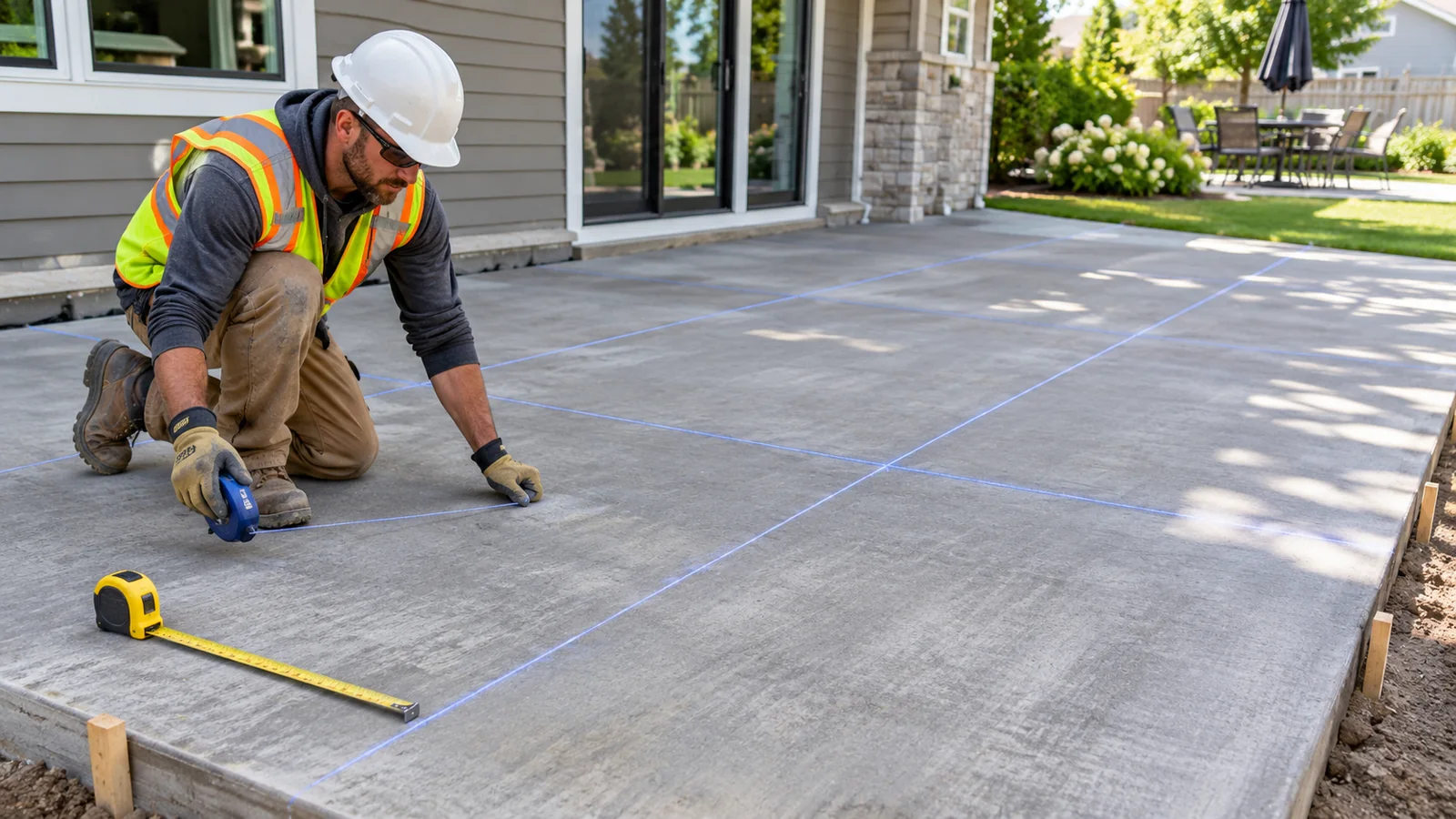
A chalk line does not authorize cutting. Confirm the approved plan and what is beneath the line first.
How to Check Joint Depth and Cutting Timing Against the Layout
Depth and timing belong to the cutting plan, and the dedicated guide covers them in detail. A short check against the layout is enough here.
- Conventional depth: NRMCA recommends a groove at least one-quarter of slab thickness and not less than 1 in.
- Early-entry sawing: generally run 1 to 4 hours after finishing, with a minimum 1 in. depth, per NRMCA.
- Conventional sawing: within 4 to 12 hours after finishing, delayed if edges ravel.
- Sequence: coordinate with the contractor’s cutting order.
- Before cutting: review embedded utilities and reinforcement.
Timing depends on concrete condition, not a fixed hour count. For the full procedure, see how to saw cut control joints in concrete, and for curing conditions see the Concrete Curing and Drying Time Guide. Early-entry systems and engineered pavement details can differ.
How to Estimate Total Control Joint Length
A takeoff adds up the length of each interior joint line. For a simple rectangular grid, use the counts of lines in each direction.
Formula: Rectangular Grid
Variables: L is the slab length and W is the slab width. nL is the number of interior joint lines running parallel to the length (each L long). nW is the number running parallel to the width (each W long).
Example: for the 20 × 30 ft slab, L = 30, W = 20, nL = 1, nW = 2. Ltotal = 1(30) + 2(20) = 70 ft.
You can also measure each joint line individually and add them. Intersecting lines do not require subtracting any length when measuring centerlines, though material quantities can depend on the joint detail.
| Item | Count | Length each | Total |
|---|---|---|---|
| Longitudinal interior joint | 1 | 30 ft | 30 ft |
| Transverse interior joints | 2 | 20 ft | 40 ft |
| Total control joints | 3 straight lines | n/a | 70 ft |
| Perimeter isolation joints | Project dependent | Measure separately | Excluded |
| Construction joints | Project dependent | Measure separately | Excluded |
Table 4. Joint layout quantity takeoff for the 20 × 30 ft slab with six 10 × 10 ft panels. Isolation openings, interruptions, and construction joints need adjusted quantities.
For a quick check, use the Concrete Joint Calculator.
Common Concrete Control Joint Layout Mistakes
Most layout mistakes come from spacing a grid without checking panel shape or restraints. Table 5 lists them with risks and corrections.
| Layout problem | Potential consequence | Corrective approach |
|---|---|---|
| Oversized panel | Greater random-cracking risk | Reduce spacing per applicable guidance |
| Panel ratio above 1.5:1 | Unfavorable panel geometry | Rebalance the grid |
| L-shaped panel | Crack concentration at the inside corner | Divide into more regular panels |
| Staggered joints | Discontinuous crack-control pattern | Align continuous joint lines |
| Joint misses a re-entrant corner | Uncontrolled corner crack | Reassess corner alignment |
| Column not isolated where required | Restrained slab movement | Use approved isolation details |
| Very narrow edge strip | Fragile or awkward panel | Redistribute panel dimensions |
| No construction-joint coordination | Misaligned joints between pours | Coordinate the pour layout |
| Cut conflicts with an embedded system | Damage or safety hazard | Verify locations and revise through approval |
| Engineered joint details ignored | Mismatch with the design | Follow the approved drawings |
Table 5. Common joint layout problems and corrections. These describe risks, not guaranteed outcomes.
How to Review and Approve a Concrete Joint Layout Plan
A final review ties the earlier checks together before concrete or saws are involved. Compare the layout with each of these items:
- Slab thickness and panel dimensions
- Restraint locations
- Structural drawings and reinforcement
- Saw-cut timing and cutting access
- Project requirements
For contractor-managed work, changes to an engineered joint layout need appropriate review, not informal field adjustments. ACI 302.1R-15 places responsibility for spacing and layout with the designer.
Concrete Control Joint Layout FAQs and Final Checklist
How do you design a concrete control joint layout?
Measure the slab, mark restraints, pick a preliminary spacing of 24 to 36 times thickness, divide each dimension into near-square panels, and check aspect ratios. Then align lines with corners and openings and verify the layout against the approved plans before cutting. Engineered plans take precedence.
How far apart should concrete control joints be?
A common planning range is 24 to 36 times slab thickness, so 8 to 12 ft for 4 in. concrete, with NRMCA suggesting a general limit near 15 ft. Closer spacing is allowed, and engineered plans, reinforcement, and project conditions can change the answer.
Should control joint panels be square?
Square is preferred. ACI 302.1R-15 prefers 1 to 1 and sets a 1.5 to 1 maximum for plain or lightly reinforced slabs, and NRMCA says length should not exceed 1.5 times width. Narrow strips and L-shaped panels should be avoided.
Can concrete control joint lines intersect?
Yes. Joints in a grid intersect at right angles, and ACI says contraction joints should be continuous, not staggered or offset. Avoid offset T-intersections that create irregular panels, and intersections that ignore a column or other restraint.
Should joints extend from inside corners?
Often yes. A joint running from a re-entrant corner to a boundary or aligned joint lets the corner crack along a planned line. The exact detail depends on slab geometry and the approved design, so there is no single mandatory cut.
Do driveways need joints in both directions?
Not always. A 12 ft wide driveway can often be divided with transverse joints only, giving about 12 × 10 ft panels. A center joint can create panels above the 1.5:1 ratio unless transverse spacing is also reduced. Check each panel’s dimensions.
Where do joints go around columns?
Columns are restraints, so they usually get an isolation opening rather than a plain contraction joint. NRMCA suggests a square opening turned 45 degrees so contraction joints meet at its corners. Follow the project’s column details.
Can I create L-shaped concrete panels?
Avoid them. ACI 302.1R-15 and NRMCA both discourage L- and T-shaped panels because stress concentrates at the inside corner. Extend a joint from the re-entrant corner so the slab divides into rectangular panels instead.
Should joints line up between separate pours?
Generally yes. Planned construction joints should fit the contraction joint grid to avoid offsets, and ACI suggests keeping a construction joint 5 ft or more from a parallel joint where possible. Follow the approved joint plan.
Can I change a joint layout after concrete placement?
Treat an engineered layout as fixed unless the designer approves a change. Cutting joints later cannot undo cracks that already formed, and a change can affect restraint, reinforcement, and load transfer. For ordinary flatwork, review changes with the responsible contractor first.
Final Layout Checklist
- Dimensions: confirm slab length, width, and thickness.
- Spacing: check the preliminary spacing and any project limits.
- Panel proportions: keep every panel at or below about 1.5:1.
- Obstacles: address corners, columns, drains, and openings.
- Isolation: mark isolation joints separately from contraction joints.
- Continuity: keep joint lines continuous and aligned.
- Embedded items: verify reinforcement and utilities before cutting.
- Construction sequence: coordinate joints between pours.
- Approval: confirm the layout with the approved plans.
A good concrete control joint layout comes from square panels, continuous lines, and attention to corners and restraints. Check your own slab dimensions in the Concrete Joint Calculator, then compare the result against the approved plans before anyone cuts.
Check Your Slab Dimensions
Enter slab length, width, and thickness to see spacing, joint counts, and panel ratios before you mark any lines.
Open the Concrete Joint Calculator