Ceiling Joist Size Chart: Sizes, Spans, Loads & Attic Storage
Ceiling Joist Size Chart: Sizes, Spans, Loads & Attic Storage
Actual dimensions for common solid-sawn ceiling joists, plus the loading case, span, spacing, grade, connection and ceiling-board factors that decide which size works.
 Reviewed by Muhammad Ramzan Babar, PhD Researcher (Plasma Physics) & Calculator Developer. View Profile
Key Facts
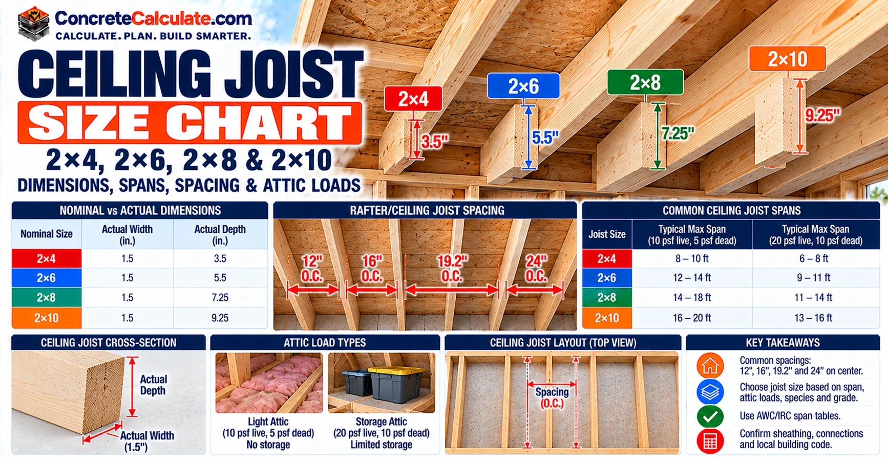
- Common solid-sawn ceiling joists are nominal 2×4, 2×6, 2×8, 2×10 and 2×12, with actual depths of 3.5, 5.5, 7.25, 9.25 and 11.25 in. and a width of 1.5 in.
- AWC publishes two ceiling-joist loading cases: C-1 (10 psf live, 5 psf dead, L/240) with no attic storage and C-2 (20 psf live, 10 psf dead, L/240) with limited storage.
- Neither case authorizes a habitable attic, and size cannot be chosen from span alone.
- A ceiling joist may also act as a rafter tie, so its connections matter as much as its size. For tabulated spans, use the Ceiling Joist Span Chart.
Ceiling Joist Size Chart: 2×4, 2×6, 2×8, 2×10 & 2×12
Common solid-sawn ceiling joist sizes with actual dimensions, plus the loading case that comes first in any size decision.
How to Read This Chart
Nominal size is the name at the lumber yard and actual size is what you measure. Read the depth column first, then use the “AWC rows” column to see which sizes the AWC ceiling-joist tables actually cover. The sections below explain the loading case, spacing, grade, stiffness and connections that decide which size is right.
| Nominal size | Actual width (in.) | Actual depth (in.) | Approx. mm (converted) | Geometric class | In AWC C-1 / C-2 rows? | Main design consideration |
|---|---|---|---|---|---|---|
| 2×4 | 1.5 | 3.5 | 38 × 89 | Shallow | Yes | Check span and ceiling or attic loads carefully |
| 2×6 | 1.5 | 5.5 | 38 × 140 | Moderate depth | Yes | Verify span, grade, spacing and ceiling load |
| 2×8 | 1.5 | 7.25 | 38 × 184 | Deeper | Yes | Greater bending stiffness potential |
| 2×10 | 1.5 | 9.25 | 38 × 235 | Deep | Yes | Greater stiffness and span potential under comparable conditions |
| 2×12 | 1.5 | 11.25 | 38 × 286 | Very deep | Not an AWC ceiling row | Special or longer-span applications where design supports it |
Dimensional References, Not Recommendations
These are dimensional references, not automatic joist-size recommendations. Select a joist using the applicable ceiling load category, clear span, spacing, lumber species and grade, bending strength, stiffness, bearing, connections and your adopted building code. For tabulated maximum spans, use the Ceiling Joist Span Chart.
Common Nominal and Actual Sizes
Every size above is 1.5 in. wide. Only the depth changes: 3.5, 5.5, 7.25, 9.25 or 11.25 in. The 2×4 is the shallowest and the 2×12 is the deepest.
Which Sizes Are Covered by AWC?
The 2024 AWC ceiling-joist tables (C-1 and C-2) include nominal 2×4, 2×6, 2×8 and 2×10 members. The 2×12 is shown here as a dimensional-lumber size, not as a row in those two tables, so a 2×12 ceiling joist needs separate design verification.
Ceiling-Only vs. Limited Attic Storage
Before choosing a size, identify which loading case applies. AWC publishes two ceiling-joist tables with different loads, and they are not interchangeable.
| Factor | No attic storage | Limited attic storage |
|---|---|---|
| AWC table | C-1 | C-2 |
| Live load | 10 psf | 20 psf |
| Dead load | 5 psf | 10 psf |
| Deflection limit | L/240 | L/240 |
| Typical intent | Ceiling below a nonstorage attic | Ceiling below a qualifying limited-storage attic |
| Habitable attic permitted by this table alone? | No | No |
| Main selection concern | Ceiling loads and structural function | Added attic load plus structural function |
What Is a Ceiling Joist?
The three structural jobs a ceiling joist can have.
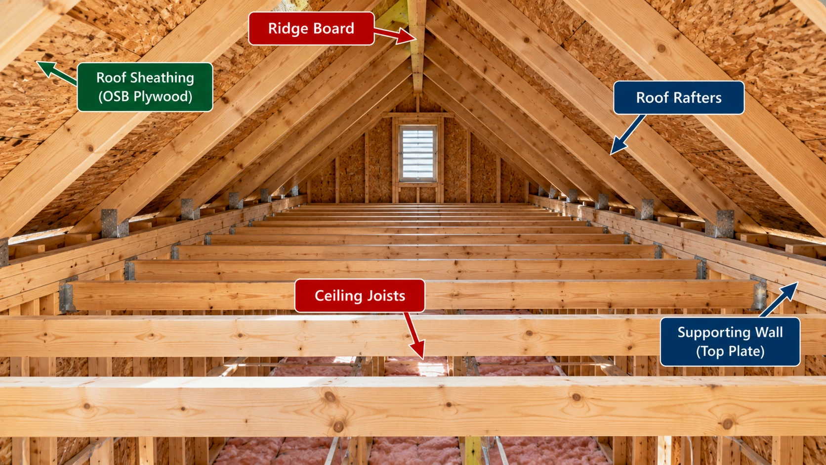
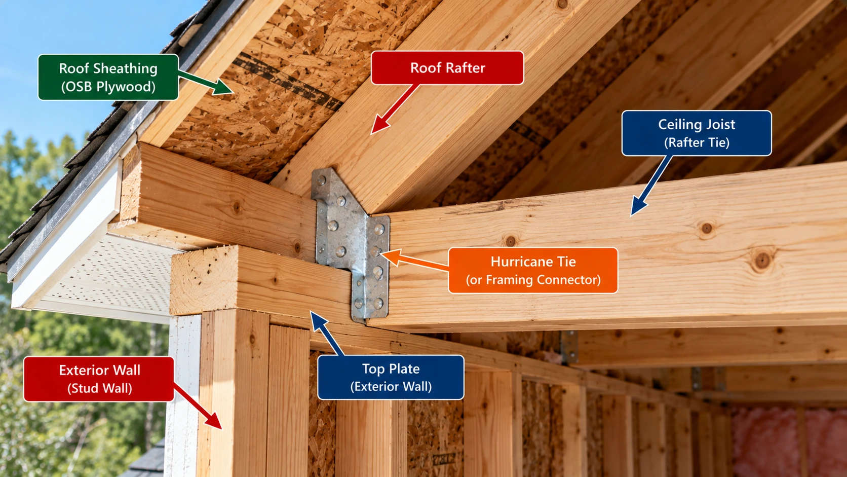
A ceiling joist is the horizontal framing member that supports the ceiling below an attic or roof. In conventional rafter framing it often does more than that, so it helps to separate the three jobs it can have.
- Ceiling support. It carries the ceiling finish, insulation and its own weight.
- Attic loads. It may carry attic loads where the applicable framing design permits, such as the limited storage case in AWC Table C-2.
- Possible rafter-tie function. When it is connected to opposing rafters near the wall plates, it can resist the outward thrust of the roof as part of a rafter-tie system.
A ceiling joist supporting an ordinary ceiling is not automatically adequate for attic storage, an occupied attic or conversion into a habitable floor. Floor framing is covered separately in the Floor Joist Size Chart.
Standard Ceiling Joist Sizes
Common nominal sizes and what sets each one apart.
Solid-sawn residential ceiling joists use nominal 2-inch lumber. The sizes in the AWC ceiling tables are 2×4, 2×6, 2×8 and 2×10, and the 2×12 is the next dimensional size for longer or specially designed applications. The geometric numbers below use actual width and depth.
2×4 Ceiling Joists
Actual size: 1.5 × 3.5 in. Geometric section modulus S = 3.06 in³ and moment of inertia I = 5.36 in⁴. It is the shallowest member that appears in the AWC ceiling tables. Because it is shallow, span, spacing, grade and loading need careful checking, and the move from no storage (C-1) to limited storage (C-2) raises the load considerably. Do not assume a 2×4 that works for an empty attic works under storage.
2×6 Ceiling Joists
Actual size: 1.5 × 5.5 in. Geometric section modulus S = 7.56 in³ and moment of inertia I = 20.80 in⁴. This is the size used for the verified AWC example later on this page. Spacing changes its deflection-based tabulated span noticeably, and species and grade change the E and Fb that apply.
2×8 Ceiling Joists
Actual size: 1.5 × 7.25 in. Geometric section modulus S = 13.14 in³ and moment of inertia I = 47.63 in⁴. A 2×8 has about 2.29 times the geometric moment of inertia of a 2×6 (47.63 / 20.80). That is a stiffness comparison only. It is a common step up when a 2×6 is close to a span limit, in either the ceiling-only or the limited-storage case.
2×10 Ceiling Joists
Actual size: 1.5 × 9.25 in. Geometric section modulus S = 21.39 in³ and moment of inertia I = 98.93 in⁴. The 2×10 has a much larger section and longer span potential under comparable conditions, but longer spans put more demand on bearing and on connections at the ends. Check the support details, not only the bending span.
2×12 Ceiling Joists
Actual size: 1.5 × 11.25 in. Geometric section modulus S = 31.64 in³ and moment of inertia I = 177.98 in⁴. The 2×12 is not a row in AWC Tables C-1 or C-2. Consider it only where a design shows it is needed, and verify it separately. Do not read its inclusion in this chart as an AWC span value.
Nominal vs. Actual Ceiling Joist Dimensions
Why the depth you measure is smaller than the size you order.
The nominal size is a name. PS 20 sets the dimensions of surfaced dry lumber (19 percent maximum moisture content), and AWC lists them as 1-1/2 × 3-1/2 in. for a 2×4, 1-1/2 × 5-1/2 in. for a 2×6, 1-1/2 × 7-1/4 in. for a 2×8, 1-1/2 × 9-1/4 in. for a 2×10 and 1-1/2 × 11-1/4 in. for a 2×12.
| Nominal size | Nominal depth (in.) | Actual depth (in.) | Difference (in.) | Actual depth (mm, converted) |
|---|---|---|---|---|
| 2×4 | 4 | 3.5 | 0.5 | 89 |
| 2×6 | 6 | 5.5 | 0.5 | 140 |
| 2×8 | 8 | 7.25 | 0.75 | 184 |
| 2×10 | 10 | 9.25 | 0.75 | 235 |
| 2×12 | 12 | 11.25 | 0.75 | 286 |
A nominal 2×6 is therefore 5.5 in. deep, not 6 in. For the full nominal-to-actual list across all lumber sizes, see the Lumber Size Chart. This page covers only the sizes used for ceiling joists.
Ceiling Joist Size vs. Span
Why clear span, not board length, is what the tables use.
Joist size and allowable span are linked, but never on their own. The span is the clear distance from face to face of the supports, not the length of the board. AWC tabulated spans are measured face to face of supports, and the tables assume at least three joists spaced not more than 24 in. on center, fully supported members, properly sheathed and nailed on the top edge.
Clear Span, Joist Length, Bearing and Support Distance
| Term | What it measures | Used for |
|---|---|---|
| Clear span | Face of one support to face of the next | Reading span tables |
| Overall joist length | Full length of the board, including bearing | Ordering lumber |
| Bearing length | Length of joist resting on each support | Bearing and crushing checks |
| Center-to-center distance | Centerline of one support to the next | Layout drawings, not span tables |
Single Spans, Continuous Joists and Laps
Ceiling joists often run from an exterior wall over an interior bearing partition to the opposite wall. Where two joists lap over a partition, the span for each is measured to the face of the supports, and the lap and fastening depend on the roof framing configuration and the adopted code. A joist that is spliced in the middle of a span interrupts its tension path and generally needs engineering approval.
For tabulated spans by size, species and spacing, go to the Ceiling Joist Span Chart. For broader species and span concepts, see the Lumber Span Chart.
Ceiling Joist Size vs. Spacing
How on-center spacing changes the load each joist carries.
The common on-center spacings in AWC ceiling-joist tables are 12, 16, 19.2 and 24 inches. Wider spacing gives each joist a wider strip of ceiling to carry. For a uniform load, the line load on one joist is the area load times the spacing in feet.
🧮 Tributary Line Load
Variables: w = line load on one joist (plf), q = area load (psf), s = joist spacing (in.). Dividing by 12 converts spacing to feet.
| Joist spacing | Tributary width | Illustrative line load (q = 15 psf) |
|---|---|---|
| 12 in. o.c. | 1.00 ft | 15 plf |
| 16 in. o.c. | 1.333 ft | 20 plf |
| 19.2 in. o.c. | 1.600 ft | 24 plf |
| 24 in. o.c. | 2.00 ft | 30 plf |
Line Load at 16 in. On Center with the C-2 Loads
What it means: This is a calculated example, not an allowable joist capacity. It also does not include any tension demand from rafter thrust. Moving to 24 in. spacing raises the line load by half under the same area load.
Gravity Load Only
This illustrates how load spreads over joists. It does not establish joist capacity or rafter-tie tension demand. Also check that your ceiling board can span the spacing you choose; see the ceiling drywall section below.
Verified AWC Ceiling Joist Span Example
Real table values showing how spacing and stiffness change the span of one joist size.
AWC Table C-1 (live load 10 psf, dead load 5 psf, L/240) gives deflection-based spans for each size at each spacing and each modulus of elasticity E. The table below shows how a 2×6 changes with spacing alone, at E = 1.4 million psi.
| 2×6 spacing | C-1 tabulated span at E = 1.4 million psi | Required Fb shown for that span (psi) |
|---|---|---|
| 12 in. | 18′-8″ | 1,033 |
| 16 in. | 16′-11″ | 1,137 |
| 19.2 in. | 15′-11″ | 1,208 |
| 24 in. | 14′-9″ | 1,302 |
Same 2×6 and Spacing, Different E
| E (million psi) | C-1 tabulated span at 16 in. o.c. | Required Fb shown (psi) |
|---|---|---|
| 1.0 | 15′-2″ | 909 |
| 1.4 | 16′-11″ | 1,137 |
| 1.8 | 18′-5″ | 1,344 |
| 2.0 | 19′-1″ | 1,442 |
Interpretation
Under the same table assumptions, wider spacing shortens the tabulated span because each joist carries a larger tributary ceiling area. A stiffer lumber (higher E) lengthens the tabulated span.
Not a Complete Allowable Span
These spans rest on the stated E and the table loading. The lumber must also have a bending design value Fb at least equal to the required Fb printed at the bottom of the table for that spacing and E, and the bearing and connection checks still apply. Higher E gives a longer tabulated span but also a higher required Fb. For the full AWC tables by size, see the Ceiling Joist Span Chart.
Ceiling Joists Without Attic Storage
AWC Table C-1: 10 psf live load and 5 psf dead load.
AWC Table C-1 assumes a live load of 10 psf and a dead load of 5 psf, with deflection limited to L/240. Deflection is checked against the live load, and the required bending design value is checked against live plus dead load. The case is meant for ceilings below attics that are not used for storage.
What Counts as an Attic Without Storage?
In the IRC, uninhabitable attics without storage are those where the maximum clear height between the joists and rafters is less than 42 in., or where there are not two or more adjacent trusses whose web configuration can fit a 42-in.-high by 24-in.-wide rectangle. The IRC lists a 10 psf live load for this case in Table R301.5, and that load need not act at the same time as other live loads.
Limitations of the No-Storage Case
C-1 is not a table for attic storage. If boxes, bins or equipment will be placed on the joists, the 20 psf limited-storage case, or a design for the actual load, is the starting point. Heavier ceiling or insulation assemblies can also need a different dead-load assumption than 5 psf.
Ceiling Joists With Limited Attic Storage
AWC Table C-2: 20 psf live load and 10 psf dead load.
AWC Table C-2 assumes a live load of 20 psf and a dead load of 10 psf, again with L/240. The higher loads shorten the allowable span compared with C-1 for the same size, spacing and lumber.
What Qualifies as Limited Attic Storage?
Under the IRC, uninhabitable attics with limited storage are those where the maximum clear height between joists and rafters is 42 in. or more, or where two or more adjacent trusses have a web configuration that can fit a 42-in. by 24-in. rectangle. The IRC lists 20 psf for this case in Table R301.5. The AWC table does not authorize a habitable attic, so treat it as unsuitable where a future room is planned.
Why 20 psf Is Not a Universal Attic-Floor Design Load
The 20 psf value is a code live load for an uninhabitable attic with limited storage. A real storage plan, such as dense stacks of boxes or equipment, can exceed it, and a habitable floor uses higher floor loads and floor-framing checks. Treat 20 psf as a table assumption.
Why Existing Ceiling Joists Must Be Evaluated Before Adding Storage
Existing joists may have been sized for the 10 psf no-storage case, with a small dead load and a particular span, spacing, species and grade. Before adding storage, confirm the actual lumber, the clear span and the condition of the framing, and check the connections. If the joists also act as rafter ties, added load and any cuts or notches can affect them too. Avoid describing a limited-storage attic as a regular floor.
Can Ceiling Joists Support a Habitable Attic?
The short answer is no, and why the ceiling tables are not enough.
No. Neither AWC C-1 nor C-2 authorizes a habitable attic. A planned bedroom, office, bathroom or substantial storage conversion needs the applicable floor-framing design and additional checks, not a ceiling-joist table.
| Topic | Ceiling-only or limited storage | Habitable attic floor |
|---|---|---|
| Governing framing | Ceiling joist tables (AWC C-1 or C-2) | Floor joist design and tables |
| Live load | 10 or 20 psf by attic condition | Floor live loads such as 30 psf (sleeping areas) or 40 psf (other residential areas) under IRC Table R301.5 |
| Deflection limit in AWC tables | L/240 | L/360 for floor joists |
| Extra checks | Connections, bearing, finish | Floor stiffness, subfloor, stairs and other requirements by the adopted code |
For floor sizing, use the Floor Joist Size Chart and the Floor Joist Span Chart. When existing joists are shallow or the conversion is substantial, an engineered evaluation is the safer path, and engineered floor members are covered in the TJI Floor Joist Span Chart.
Ceiling Joist Live Load vs. Dead Load
What counts as each kind of load on a ceiling joist.
Live load is the load from use, such as stored items or maintenance. Dead load is the permanent weight of the construction. For ceiling joists, dead load includes the ceiling finish, insulation, the joists themselves and any permanent equipment.
- Ceiling finishes: gypsum board, plaster or other ceiling material.
- Insulation: USG notes a limit of 2.2 lb/sq ft for unsupported insulation on its UltraLight ceiling panels receiving water-based texture, so insulation weight can matter.
- Framing self-weight: the joists and any blocking.
- Permanent equipment: fixtures or ducts hung from the framing.
- Storage loads: live load in the limited-storage case.
AWC C-1 uses a 5 psf dead load and C-2 uses 10 psf, so heavy assemblies and permanent equipment can need a different assumption. To combine your own loads, use the Live and Dead Load Calculator.
Why Ceiling Joist Depth Matters
How section modulus and moment of inertia grow with depth.
For a rectangular section, bending strength depends on the section modulus S, and bending stiffness depends on the moment of inertia I. Both rise sharply with depth because depth is squared in S and cubed in I, while width stays at 1.5 in.
Section Modulus and Moment of Inertia
🧮 Formulas
Variables: S = section modulus (in3), I = moment of inertia (in4), b = actual width (in.), d = actual depth (in.).
| Nominal size | Actual dimensions | Section modulus S (in³) | Moment of inertia I (in⁴) |
|---|---|---|---|
| 2×4 | 1.5 × 3.5 in. | 3.06 | 5.36 |
| 2×6 | 1.5 × 5.5 in. | 7.56 | 20.80 |
| 2×8 | 1.5 × 7.25 in. | 13.14 | 47.63 |
| 2×10 | 1.5 × 9.25 in. | 21.39 | 98.93 |
| 2×12 | 1.5 × 11.25 in. | 31.64 | 177.98 |
Not Allowable Capacities
These are calculated geometric properties, not manufacturer-published or code allowable capacities. Depth is not equivalent to allowable span: stiffness E, bending design value Fb, connections and loading all still matter.
2×8 Compared With 2×6
What it means: This does not mean 2.29 times the allowable load or span. Use it to see why deeper members are stiffer, then check the real design inputs.
Ceiling Joist Deflection Requirements
L/240, how it differs from floors, and what it does not guarantee.
The AWC ceiling-joist tables limit deflection to L/240, where L is the clear span in inches. The limit is looser than the L/360 used in the AWC floor joist tables. Deflection is checked under the live load only, while the bending check uses live plus dead load together.
Understanding L/240
🧮 Deflection Limit
Variables: Δallow = allowable deflection (in.), L = clear span (in.). Multiply feet by 12 to get inches.
| Clear span | Span in inches | L/240 limit (in.) |
|---|---|---|
| 8 ft | 96 in. | 0.400 in. |
| 10 ft | 120 in. | 0.500 in. |
| 12 ft | 144 in. | 0.600 in. |
| 14 ft | 168 in. | 0.700 in. |
| 16 ft | 192 in. | 0.800 in. |
| 18 ft | 216 in. | 0.900 in. |
L/240 for a 12-ft Span
What it means: This is the allowable deflection, not the joist’s predicted actual deflection.
Simplified Deflection Relationship
🧮 Simply Supported Beam, Uniform Load
Variables: w = line load in lb/in., L = span in inches, E = modulus of elasticity in psi, I = moment of inertia in in4. Use the load component that matches the deflection criterion (live load for the AWC ceiling tables).
Illustrative Deflection of a 2×6 at 12 ft
What it means: This is an illustrative elastic-beam calculation only. It checks one criterion and says nothing about bending, bearing or connections.
Ceiling Finish Performance
A joist that meets L/240 can still let a ceiling sag, crack at joints or show fastener pops if the ceiling board, spacing, texture and insulation are not compatible. Product-specific ceiling requirements are covered in the drywall section below, and the Beam Deflection Chart and Beam Deflection Calculator explain deflection in more depth.
Ceiling Joist Lumber Species
The same size and grade can behave differently in different species.
Different species and species groups have different design properties. Common framing species in the U.S. include Douglas Fir-Larch, Hem-Fir, Southern Pine and Spruce-Pine-Fir, along with other recognized species and groups. The E and Fb values used with the AWC tables come from the AWC Design Values for Joists and Rafters supplement.
That is why “a No. 2 2×6 always spans X feet” is never safe. Grades are not interchangeable across species: a No. 2 joist of one species can have a different E and Fb than a No. 2 joist of another. For species-by-species spans, go to the Ceiling Joist Span Chart and the Lumber Span Chart.
Ceiling Joist Lumber Grade
What the grade stamp tells you and why it changes the answer.
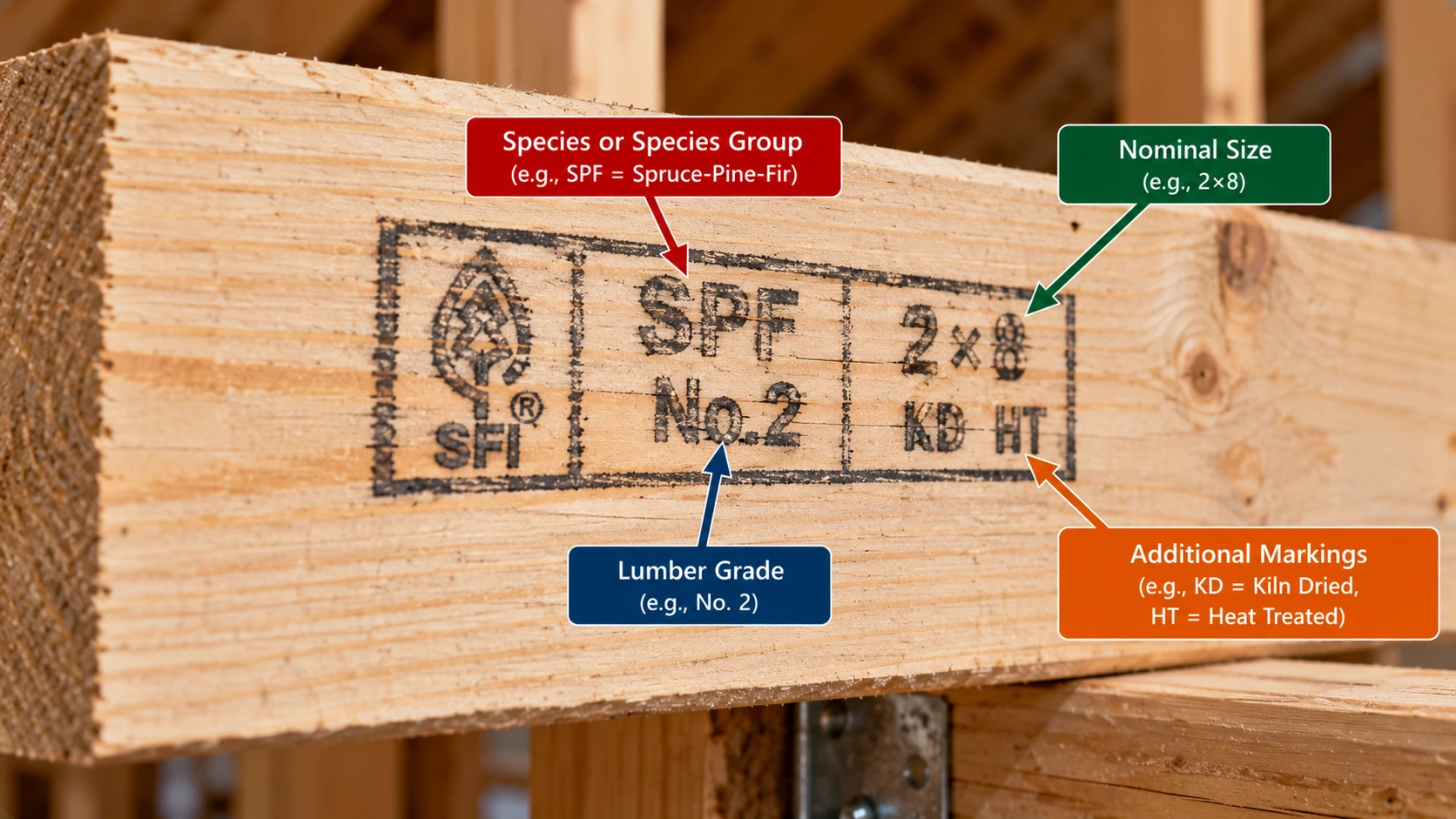
A lumber grade stamp identifies the species or species group, the grade, the grading agency and the mill, and AWC requires that tabulated spans apply to lumber identified by a recognized grade stamp or certificate of inspection. Common grade names include Select Structural and numbered grades such as No. 1, No. 2 and No. 3, but which grades exist and what design values they carry depend on the species.
A “No. 2” label alone is therefore not enough to choose a joist. You need the species and grade together.
Understanding E and Fb
The stiffness check and the strength check, and why both are needed.
Two design values do most of the work in AWC ceiling-joist tables, and they answer different questions.
| Property | Meaning | What it controls | Common mistake |
|---|---|---|---|
| E | Modulus of elasticity (psi) | Stiffness and the L/240 deflection check | Treating stiffness as strength |
| Fb | Bending design value (psi) | Bending strength check of the extreme fibers | Treating it as a maximum load or as stiffness |
The method is to choose a trial species, size and grade, find E and Fb in the design values supplement, read the tabulated span for that E, and then confirm that the lumber’s Fb is at least the required Fb printed at the bottom of the table. AWC also lists a required compression perpendicular to grain value, Fc⊥, for bearing, which is covered in the bearing section below.
Ceiling Joists vs. Floor Joists
Different loads, different tables, different jobs.
Ceiling joists and floor joists look alike, but they are not designed with the same assumptions. AWC treats them in separate table families.
| Topic | Ceiling joists | Floor joists |
|---|---|---|
| AWC tables | C-1 and C-2 | F-1 to F-7 |
| Live loads in tables | 10 or 20 psf | 30 to 60 psf |
| Dead loads in tables | 5 or 10 psf | 10 or 20 psf |
| Deflection limit | L/240 | L/360 |
| Typical function | Ceiling support, limited attic loads, possible rafter tie | Occupied floor support |
| Attic conversion | Not authorized by C-1 or C-2 | Needs floor design and checks |
For floor framing, see the Floor Joist Size Chart and the Floor Joist Span Chart. Never size an attic floor from a ceiling table.
Ceiling Joists vs. Rafter Ties
Gravity support versus tension restraint, and when one member does both.
A ceiling joist carries gravity load in bending. A rafter tie resists the outward thrust that sloped rafters push onto the exterior walls, and it does that in tension. In conventional roof framing, a ceiling joist that is properly connected to the rafters near the wall plates can do both jobs.
The model IRC treats ceiling-joist sizing and rafter-tie detailing separately. The 2024 IRC (Section R802.5.2) calls for ceiling joists that run parallel to rafters and sit in the bottom third of the rafter height to be installed per the code figure and fastened to the rafters per Table R802.5.2(1). Where ceiling joists are used to resist rafter thrust, lapped joists must be nailed together and butted joists must be tied together to resist that thrust.
The key point is that a joist that is adequate in bending can still be inadequate in tension. A heel joint or lap that is under-fastened can fail even when the joist passes its span table. Roof geometry matters too, so see the Roof Pitch Chart, the Roof Rafter Span Chart and the Roof Rafter Size Chart.
Gravity and Tension Are Different Checks
Do not conflate gravity loads with rafter-tie tension. Bending span adequacy does not establish that the tension connections are adequate. Section numbers and tables vary by IRC edition, so confirm them in the edition your jurisdiction has adopted.
Ceiling Joists vs. Collar Ties
Where each member sits and why one cannot replace the other.
Collar ties and rafter ties are different members in different places. A rafter tie, which is often the ceiling joist, sits at or near the bottom of the rafters and resists outward thrust at the walls. A collar tie sits in the upper part of the attic space and connects opposing rafters near the ridge.
| Member | Typical location | Main structural function |
|---|---|---|
| Ceiling joist | Bottom of the attic space, across the walls | Supports the ceiling; can also resist thrust as a rafter tie |
| Rafter tie | At or near the bottom of the rafters | Resists outward thrust at the exterior walls |
| Collar tie | Upper third of the attic space | Connects opposing rafters near the ridge; resists wind uplift where required |
A collar tie high in the attic does not do the job of a low tie. It sits too near the ridge to hold the walls from spreading, so it cannot simply replace the lower rafter tie. The IRC uses collar ties or ridge straps to resist wind uplift, connected in the upper third of the attic space. Confirm the details in your adopted code.
Ceiling Joist Connections and Lap Joints
Why a joist that passes its span table can still fall short at the connection.
Connections turn individual members into a roof system. Where a ceiling joist acts as a rafter tie, the joist-to-rafter connection and the joist-to-top-plate connection carry tension, so their fasteners matter as much as the lumber size.
- Joist-to-rafter fastening: follows the IRC fastening table for the roof configuration (Table R802.5.2(1) in the 2024 IRC).
- Joist-to-top-plate fastening: follows the applicable IRC fastening provisions for wall connections.
- Continuous ties: the ties across the structure must be continuous in a conventional roof, whether they are ceiling joists or separate rafter ties.
- Laps over interior bearing partitions: where joists are lapped, the lap and its fastening depend on the roof configuration and the adopted code, and the lapped joists must be tied together if they resist thrust.
- Approved engineered alternatives: engineered connectors or designs are permitted when approved.
This page does not list nail counts or lap lengths. Take them from the fastening table in your adopted code or from an engineer, because they vary with roof pitch, rafter spacing and loading.
Ridge Board vs. Structural Ridge Beam
Why the choice changes the tie requirement.
In conventional framing, a ridge board is a non-structural prop that opposing rafters nail against. The IRC requires it to be at least 1 inch nominal thickness and not less in depth than the cut end of the rafter. This arrangement depends on the roof being tied across the structure, usually by ceiling joists or rafter ties, so the walls do not spread.
Where ceiling joists or rafter ties do not provide continuous ties across the structure, the ridge must be supported by a wall or by a ridge beam designed in accordance with accepted engineering practice and supported at each end by a wall or column. Roofs with a pitch flatter than 3:12 also need structural members at the ridge designed as beams under the IRC prescriptive rules. A structural ridge beam changes the tie requirements, but it must be designed for the loads it carries.
| Feature | Ridge board | Structural ridge beam |
|---|---|---|
| Role | Non-structural prop for opposing rafters | Supports the rafter ends and carries vertical roof load |
| Roof tied across the structure? | Yes, by ceiling joists or rafter ties | Used where continuous ties are not provided or pitch is below 3:12 |
| Sizing basis | Minimum 1 in. nominal thickness and depth of the rafter cut | Engineering design for the loads and span |
| Supported at ends? | Not required | Yes, by a wall or column |
Pitch affects which approach is allowed. The Roof Pitch Calculator and Roof Pitch Chart help confirm your slope, and the Roof Truss Span Chart covers roofs framed with trusses instead of rafters and joists.
Ceiling Joist Bearing and Support
Support conditions are part of the size decision.
The ends of a ceiling joist must resist the support reaction without crushing the wood. AWC Table 9.1 lists the required compression perpendicular to grain, Fc⊥, for simple-span joists at a base load of 66.67 plf, and Table 9.2 gives factors for other loads and spacings. For the C-1 load (10 psf live, 5 psf dead), the factors are 0.23, 0.30, 0.36 and 0.45 at 12, 16, 19.2 and 24 in. on center. For C-2 (20 live, 10 dead) they are 0.45, 0.60, 0.72 and 0.90.
Required Fc⊥ at a 12-ft Span, 16 in. On Center
What it means: The lumber used must have a compression perpendicular to grain design value at or above this requirement. This is a table-based calculation for illustration, not a full bearing design.
Support types include exterior walls, interior bearing partitions, beams and hangers. The IRC is commonly cited for a minimum of 1-1/2 in. of bearing on wood or metal, with more on masonry, so confirm the bearing rule in your adopted code. For supporting beams and openings, see the Wood Beam Span Chart and the Header Span Chart. If a hanger is used, it must be rated for the member and used with its specified fasteners.
Ceiling Drywall Thickness and Joist Spacing
How the ceiling board can limit joist spacing even when the joist is strong enough.
A ceiling can pass its structural joist check and still sag if the board, orientation and spacing do not match. The table below is a narrowly sourced example from the USG Sheetrock installation guide for single-layer application to wood framing. It is product and application guidance, not a universal rule for every brand, fire-rated assembly, texture or insulation condition.
| Gypsum panel | Board orientation to framing | Max. framing spacing (in. o.c.) | Conditions in USG notes |
|---|---|---|---|
| Conventional 3/8 in. | Perpendicular | 16 | Not recommended below unheated spaces or with water-based texture |
| Conventional 1/2 in. | Parallel | 16 | Not recommended with water-based texture |
| Conventional 1/2 in. | Perpendicular | 24 | 16 in. if water-based texture is applied |
| Conventional 5/8 in. | Parallel | 16 | Not recommended with water-based texture |
| Conventional 5/8 in. | Perpendicular | 24 | No extra note listed in the guide table |
| USG UltraLight 1/2 in. | Parallel or perpendicular | 24 | Product-specific; see conditions below |
Specialty Boards Differ
The USG UltraLight submittal lists 24 in. on center for both parallel and perpendicular application on ceilings that receive water-based texture, with unsupported insulation not exceeding 2.2 lb/sq ft. That is a product-specific capability and does not carry over to conventional board. A structurally adequate 24-in. joist layout is therefore not automatically suitable for every gypsum ceiling product.
For board thickness by use, see the Drywall Thickness Chart, and for fastening, the Drywall Screw Spacing Chart. To estimate ceiling area and board quantity, use the Ceiling Square Footage Calculator and the Drywall Calculator.
Ceiling Joist Holes and Notches
Solid-sawn member limits applied to actual depths, with the limits of those limits.
For solid-sawn lumber, the IRC limits bored holes to a diameter of one-third of the member depth, keeps holes at least 2 in. from the top and bottom edges and from other holes, and limits notches. The tables apply those limits to the actual depths in this chart.
| Nominal size | Actual depth (in.) | One-third depth (in.) | Depth minus 4 in. (2 in. each edge) | Largest hole meeting both (in.) |
|---|---|---|---|---|
| 2×4 | 3.5 | 1.17 | none | none |
| 2×6 | 5.5 | 1.83 | 1.50 | 1.50 |
| 2×8 | 7.25 | 2.42 | 3.25 | 2.42 |
| 2×10 | 9.25 | 3.08 | 5.25 | 3.08 |
| 2×12 | 11.25 | 3.75 | 7.25 | 3.75 |
| Nominal size | Actual depth (in.) | Max notch depth, d/6 (in.) | Max notch length, d/3 (in.) | Max end notch depth, d/4 (in.) |
|---|---|---|---|---|
| 2×4 | 3.5 | 0.58 | 1.17 | 0.88 |
| 2×6 | 5.5 | 0.92 | 1.83 | 1.38 |
| 2×8 | 7.25 | 1.21 | 2.42 | 1.81 |
| 2×10 | 9.25 | 1.54 | 3.08 | 2.31 |
| 2×12 | 11.25 | 1.88 | 3.75 | 2.81 |
Penetrations, Engineered Members and Ties
These are mathematical applications of the limits, not permission to drill or cut anywhere within them. Electrical and mechanical penetrations still have to respect edge distances and notch locations. Cuts, holes and notches in trusses, I-joists and other engineered members are prohibited unless the manufacturer allows them or a design professional accounts for them. A joist that also acts as a rafter tie can lose tension capacity if it is cut or notched, so ask a designer before altering one.
Blocking and Lateral Restraint
What lateral restraint does and what it cannot promise.
Blocking and bridging help keep joists aligned and plumb, limit rotation, and support the ceiling assembly. AWC states that the tabulated spans assume fully supported members, properly sheathed and nailed on the top edge, and that adequate bracing and bridging to resist wind and other lateral forces must be provided.
Do not claim that blocking raises a joist’s allowable span by a fixed percentage. No such universal rule exists, and the detail depends on the adopted code and the joist depth.
How to Choose Ceiling Joist Size
A decision sequence you can follow, instead of a one-line size table.
- Determine ceiling and attic use. Empty attic, limited storage or a planned future room.
- Determine loads. Live load, and dead load from the ceiling finish, insulation and framing.
- Measure the clear span. Face of support to face of support.
- Select spacing. 12, 16, 19.2 or 24 in. on center, considering the ceiling board.
- Identify lumber species and grade. And get E and Fb from the design values supplement.
- Check AWC or IRC tables. Use C-1 or C-2 for the matching load, then confirm the required Fb and bearing.
- Verify connections and finish. Rafter-tie fastening, laps, bearing, holes, notches and ceiling board compatibility.
| Variable | Effect on joist selection | Can it be ignored? |
|---|---|---|
| Loading case (C-1 or C-2) | Sets live and dead load | No |
| Clear span | Major | No |
| Joist depth | Major | No |
| Joist spacing | Major | No |
| Species and grade | Set E and Fb | No |
| E | Controls the L/240 deflection check | No |
| Fb | Controls the bending-strength check | No |
| Rafter-tie function | Adds tension demand at connections | No |
| Bearing and connections | Required support condition | No |
| Ceiling board | Can limit spacing | No |
| Holes and notches | Can reduce member capacity | No |
Use the Lumber Calculator for quantities, the Beam Size Calculator for any beam that supports the joists, and the Ceiling Joist Span Chart to read tabulated spans. If a trial joist fails, change the depth, the spacing, the grade or species, or the framing arrangement.
Ceiling Joist Size for Common Spans
Popular span questions answered without pretending one size fits every ceiling.
Span searches are common, but a safe answer needs the same inputs every time. Each entry gives the deflection limit that applies at that clear span and points to where the real answer comes from. These are not size recommendations.
8-Foot Span
There is no single size for a 8-ft span. A 8-ft clear span is 96 in., so its L/240 limit is 0.40 in. Short spans are where shallow members such as the 2×4 appear in the code tables, but the loading case and spacing still decide the result. Identify the loading case, spacing, species, grade, E and Fb, then read the tabulated spans in the Ceiling Joist Span Chart.
10-Foot Span
There is no single size for a 10-ft span. A 10-ft clear span is 120 in., so its L/240 limit is 0.50 in. Check whether the attic will stay empty, because storage changes the loading case. Identify the loading case, spacing, species, grade, E and Fb, then read the tabulated spans in the Ceiling Joist Span Chart.
12-Foot Span
There is no single size for a 12-ft span. A 12-ft clear span is 144 in., so its L/240 limit is 0.60 in. Spacing alone can change the tabulated span noticeably, as the AWC 2×6 example earlier on this page shows. Identify the loading case, spacing, species, grade, E and Fb, then read the tabulated spans in the Ceiling Joist Span Chart.
14-Foot Span
There is no single size for a 14-ft span. A 14-ft clear span is 168 in., so its L/240 limit is 0.70 in. Compare more than one size and spacing, and confirm the clear span is measured face to face of the supports. Identify the loading case, spacing, species, grade, E and Fb, then read the tabulated spans in the Ceiling Joist Span Chart.
16-Foot Span
There is no single size for a 16-ft span. A 16-ft clear span is 192 in., so its L/240 limit is 0.80 in. A building dimension is not a clear span, so measure between the actual faces of the supports. Longer spans also put more demand on bearing and connections. Identify the loading case, spacing, species, grade, E and Fb, then read the tabulated spans in the Ceiling Joist Span Chart.
18-Foot Span
There is no single size for a 18-ft span. A 18-ft clear span is 216 in., so its L/240 limit is 0.90 in. An 18-ft clear span needs boards longer than 18 ft once bearing is included, and AWC advises checking availability of lumber longer than 20 ft. Check whether trusses, covered in the Roof Truss Span Chart, or engineered framing are a better fit. Identify the loading case, spacing, species, grade, E and Fb, then read the tabulated spans in the Ceiling Joist Span Chart.
Common Ceiling Joist Sizing Mistakes
The errors that cause the most trouble when people pick a ceiling joist size.
Choosing size from span alone
Picking a size from span alone or using a simple “span to joist size” chart without checking its assumptions.
Treating ceiling joists as floor joists
Using floor tables for a ceiling or, worse, using a ceiling table for an attic floor.
Ignoring attic storage
Applying C-1 (no storage) to an attic that will hold boxes, or treating C-2 as permission for a habitable attic.
Mixing up E and Fb
Reading a deflection-based span as a final allowable span without checking the required Fb, or confusing stiffness with strength.
Treating all No. 2 lumber as equal
Ignoring species and grade, or assuming one grade stamp value applies to every species.
Ignoring spacing and ceiling board
Forgetting that wider spacing raises each joist’s load and that some ceiling boards need closer framing.
Wrong span measurement
Measuring overall board length or center-to-center distance instead of the clear span.
Nominal vs. actual
Assuming a nominal 2×6 is 6 in. deep or that a 2×12 appears in the AWC ceiling tables.
Misreading calculated numbers
Treating L/240 as predicted deflection, geometric I as allowable capacity, or a 2×8 as “2.29 times stronger” than a 2×6.
Gravity-only thinking
Assuming a joist that passes its bending span also passes as a rafter tie, or that a collar tie can replace the lower tie.
Weak connections and laps
Under-fastening heel joints, short or unfastened laps, or splicing joists mid-span.
Wrong ridge assumption
Using a ridge board where continuous ties are missing or the pitch is below 3:12.
Bad holes and notches
Oversized holes, holes too close to an edge, notches in the middle third, or any cuts in trusses or engineered members.
Overlooking bearing and hangers
Ignoring bearing length, interior bearing partitions, or hanger and fastener requirements.
Ignoring insulation weight
Overlooking the dead load of heavy insulation, especially over sag-prone ceiling board.
Skipping local code
Ignoring the adopted code edition, local amendments, damaged lumber or moisture and decay.
Ceiling Joist Size FAQs
Straight answers to the questions people ask most about ceiling joist sizes.
What is the standard ceiling joist size?
No single size is standard. Nominal 2×4, 2×6, 2×8 and 2×10 members appear in the AWC ceiling-joist span tables, and the right one depends on the loading case, clear span, spacing, species and grade.
What size lumber is used for ceiling joists?
Conventional ceiling joists are nominal 2-inch lumber, commonly 2×4 through 2×10, with 2×12 used where a design supports it. Actual sizes are 1.5 in. wide by 3.5, 5.5, 7.25, 9.25 or 11.25 in. deep.
Can 2×4 lumber be used for ceiling joists?
Yes. 2×4 members appear in the AWC ceiling-joist tables, subject to span, spacing, loading, species, grade and connection requirements.
What size ceiling joists do I need?
Identify the attic loading case, measure the clear span, choose a spacing, identify the species and grade, and check the AWC or IRC tables with the lumber’s E and Fb. Then verify bearing, connections and ceiling board compatibility. Span alone is not enough.
What size ceiling joists are needed for attic storage?
Start with AWC Table C-2 (20 psf live, 10 psf dead, L/240) instead of C-1 (10 psf live, 5 psf dead). No size can be named without the span, spacing, species and grade. See the Ceiling Joist Span Chart.
Can ceiling joists support attic storage?
Only limited storage under the conditions behind AWC Table C-2, and only if the actual joists, span and connections check out. It is not a floor and does not make a habitable attic.
Can I store boxes on ceiling joists?
Light, limited storage may be acceptable where the joists were designed for it, but joists sized for an empty attic may not be. Confirm the lumber, span and loading before adding storage.
Can I convert an attic with ceiling joists into a bedroom?
Not on the strength of the ceiling joists. A bedroom, office or bathroom needs floor framing designed for floor loads, with additional checks. See the Floor Joist Size Chart.
Are ceiling joists the same as floor joists?
No. AWC treats them in separate tables with different loads and deflection limits (L/240 for ceiling joists, L/360 for floor joists), and they can serve different structural functions.
Can ceiling joists be 24 inches on center?
AWC provides 24 in. spacing rows, but the joist capacity, the rafter-tie connections and the ceiling board must all be checked for that spacing.
What size drywall works with 24-inch ceiling framing?
In the USG guide, 1/2 in. conventional board applied perpendicular and 5/8 in. conventional board applied perpendicular are listed for 24 in. spacing, with 1/2 in. dropping to 16 in. if water-based texture is applied. USG UltraLight 1/2 in. is listed for 24 in. in either orientation. This is product guidance, so see the Drywall Thickness Chart.
What is the ceiling joist deflection limit?
The cited AWC ceiling-joist tables use L/240 for their specified loading cases.
How much can a ceiling joist deflect?
Under L/240, the allowable deflection is the span in inches divided by 240. A 12-ft span (144 in.) is limited to 0.60 in. That is a limit, not a prediction of actual deflection.
How far can a 2×4 ceiling joist span?
It depends on the loading case, spacing, species, grade, E and Fb. Use the Ceiling Joist Span Chart for tabulated values.
How far can a 2×6 ceiling joist span?
It depends on the loading case and lumber. In AWC Table C-1 at E = 1.4 million psi, the deflection-based tabulated span runs from 18′-8″ at 12 in. on center to 14′-9″ at 24 in. on center, and the required Fb must also be met. See the Ceiling Joist Span Chart for full tables.
How far can a 2×8 or 2×10 ceiling joist span?
There is no single maximum. The span depends on the loading case, spacing, species, grade, E and Fb. Use the Ceiling Joist Span Chart for tabulated values.
What size ceiling joist do I need for a 10-, 12-, 14-, 16- or 18-foot span?
There is no single size for any span. The L/240 limits are 0.50 in. at 10 ft, 0.60 in. at 12 ft, 0.70 in. at 14 ft, 0.80 in. at 16 ft and 0.90 in. at 18 ft, but the size comes from the table that matches your loading, spacing and lumber.
What size ceiling joist do I need for 16 inch spacing?
16 in. on center is one of the common spacings in the AWC tables, but size still depends on span, loading case, species and grade. See the Ceiling Joist Span Chart.
What is the difference between ceiling joists and rafter ties?
A ceiling joist supports the ceiling in bending. A rafter tie resists the outward thrust of the rafters in tension. A ceiling joist connected to the rafters near the wall plates can do both.
Can a collar tie replace a rafter tie?
No. A collar tie sits in the upper part of the attic space and connects opposing rafters near the ridge. It does not hold the walls from spreading the way a low tie does.
Is a ridge board enough to hold the rafters?
A ridge board is a non-structural prop. It works where the roof is tied across the structure, usually by ceiling joists or rafter ties. Without continuous ties, or in roofs flatter than 3:12, the ridge generally needs to be a designed structural beam.
Does joist species matter?
Yes. Different species and species groups have different E and Fb values, which changes both the deflection and bending checks.
Does joist grade matter?
Yes. The grade stamp identifies species, grade, grading agency and mill, and grade changes the design values.
What does Fb mean for ceiling joists?
Fb is the bending design value in psi. It is used to check bending strength, and the lumber’s Fb must meet the required value printed in the span table.
What does E mean for ceiling joists?
E is the modulus of elasticity, a measure of stiffness. It is used in the L/240 deflection check.
Is a 2×8 much stronger than a 2×6?
Geometrically, a 2×8 has about 2.29 times the moment of inertia (stiffness) and about 1.74 times the section modulus (bending strength) of a 2×6. Real capacity also depends on species, grade, spacing and loading, so do not read these as span or load ratios.
Does closer joist spacing make a ceiling stronger?
Closer spacing reduces the tributary load on each joist under the same area load. Complete performance still depends on the full set of design checks.
Can I drill holes in ceiling joists?
In solid-sawn joists, the IRC limits bored holes to one-third of the depth, with at least 2 in. kept from the top and bottom edges and from other holes. A 2×4 is too shallow to meet the 2 in. edge rule.
How big a hole can I drill in a 2×6 ceiling joist?
The one-third limit gives about 1.83 in. for a 5.5 in. deep joist, but the 2 in. edge rule leaves only 1.50 in., so 1.50 in. is the largest hole that meets both.
Can I notch a ceiling joist?
For solid lumber, notch depth is limited to one-sixth of the depth, notch length to one-third of the depth, and notches are not allowed in the middle third of the span. End notches are limited to one-fourth of the depth.
Do ceiling joists need blocking?
The adopted code and the design decide. Blocking helps with alignment and lateral restraint, but it does not add a fixed amount of span.
How many ceiling joists do I need?
Divide the run by the spacing to get spaces, for example 24 ft (288 in.) at 16 in. gives 18 spaces. A simple starting count is spaces plus one, then adjust for partitions, openings and boundary framing.
Cite or Embed This Chart
📄 Print or Save This Chart as PDF
Use your browser’s print function to save the page as a PDF reference for jobsite binders and estimating folders.
Sources and Standards Used
Dimensions, tabulated spans and bearing values come from the AWC tables. IRC provisions are cited from the model code, so confirm the edition and any local amendments adopted in your jurisdiction. Ceiling-board spacing comes from USG product literature and is product specific. Values such as section properties, tributary loads, deflection limits and hole and notch sizes are calculated from the cited rules and are marked as derived.
- AWC, Span Tables for Joists and Rafters (2024 edition), Tables C-1, C-2, 9.1 and 9.2
- ICC, 2024 International Residential Code, R802.5.2 Ceiling joist and rafter connections
- ICC, International Residential Code, R301.5 Live load
- USG, Sheetrock Brand Installation and Finishing Guide (J371)
- USG, Sheetrock UltraLight Panels Technical Submittal