Lag Bolt Sizes Chart – Diameter, Length, TPI & Socket Size
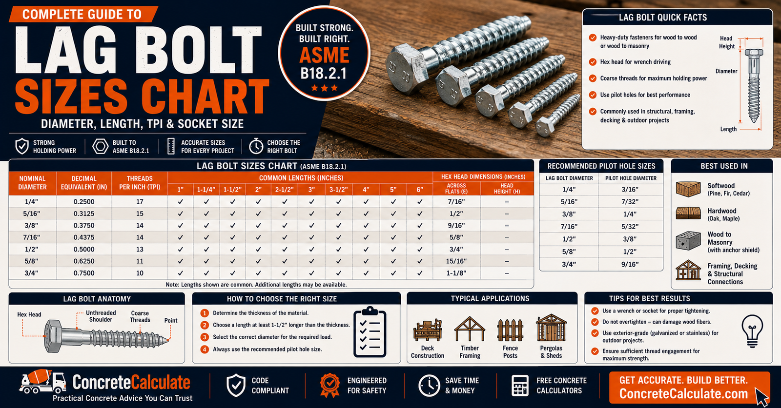
Lag Bolt Sizes Chart
Diameter, Length, TPI & Socket Size
The complete lag screw dimensional reference: diameter, decimal size, common lengths, threads per inch, hex head dimensions, socket sizing, and pilot hole chart.
 Reviewed by Muhammad Ramzan Babar, PhD Researcher (Plasma Physics) & Calculator Developer, View Profile
This chart covers dimensions, not structural capacity
Diameter and length data below are standardized dimensional reference values, not a load capacity table. Lag screw connection capacity depends on wood species, penetration, load direction, edge and end distances, and the applicable design standard. Structural connections should be designed using the NDS or a qualified design professional.
Lag Bolt Sizes Chart, Quick Reference
Standard inch-series lag screw dimensions per ASME B18.2.1. Not every diameter is available in every length commercially; check the specific manufacturer for actual stocked sizes.
| Nominal Diameter | Decimal Diameter (in.) | Common Lengths | Threads per Inch | Head Type | Basic Socket Size |
|---|---|---|---|---|---|
| 1/4″ | 0.250 | 1 1/2″ to 6″ | 10 | Hex, square | 7/16″ |
| 5/16″ | 0.3125 | 1 1/2″ to 6″ | 9 | Hex, square | 1/2″ |
| 3/8″ | 0.375 | 2″ to 8″ | 7 | Hex, square | 9/16″ |
| 7/16″ | 0.4375 | 2″ to 8″ | 7 | Hex, square | 5/8″ |
| 1/2″ | 0.500 | 2″ to 12″ | 6 | Hex, square | 3/4″ |
| 5/8″ | 0.625 | 3″ to 12″ | 5 | Hex, square | 15/16″ |
| 3/4″ | 0.750 | 3″ to 12″ | 4.5 | Hex, square | 1 1/8″ |
| 7/8″ | 0.875 | 4″ to 12″ | 4 | Hex, square | 1 5/16″ |
| 1″ | 1.000 | 4″ to 12″ | 3.5 | Hex, square | 1 1/2″ |
Source: ASME B18.2.1, Square, Hex, Heavy Hex, and Askew Head Bolts and Hex, Heavy Hex, Hex Flange, Lobed Head, and Lag Screws, Inch Series. Common length ranges are typical commercial availability, not a guarantee that every length exists for every diameter and manufacturer.
What Is a Lag Bolt?
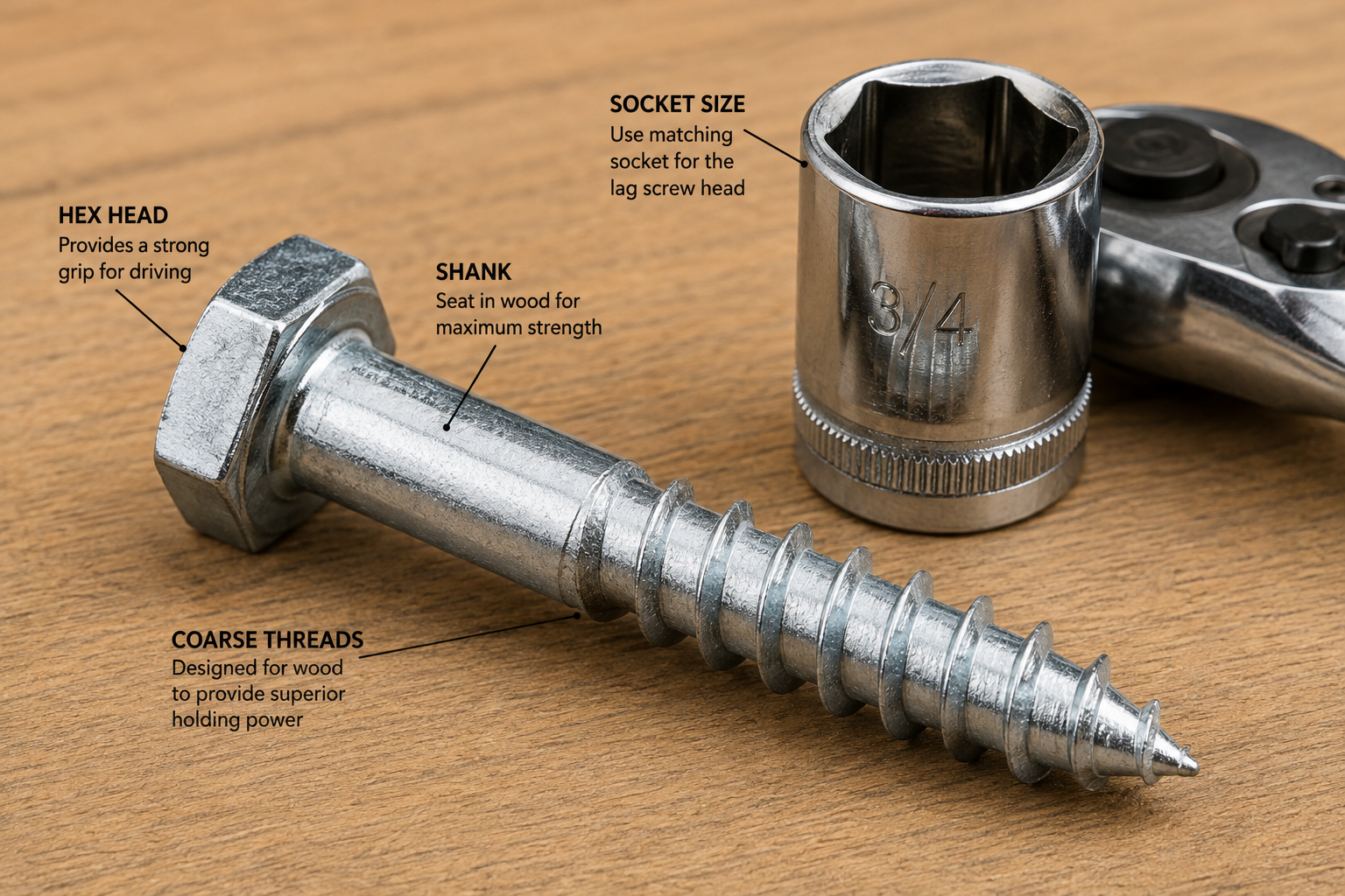
A lag bolt is a large-diameter, coarse-threaded fastener with a hex or square head, designed to thread directly into wood for heavy-duty wood connections.
Lag bolts feature a substantially larger diameter and coarser thread than typical wood screws, along with a hex or square drive head designed for wrench or socket installation rather than a screwdriver bit. They are commonly used for heavy-duty wood-to-wood connections such as beam-to-post attachments, deck framing, and general structural wood fastening where a bolt’s through-hole and nut are not practical or where one side of the connection is not accessible.
Lag Bolt vs Lag Screw
These terms refer to the same fastener. Lag bolt is the common everyday term, while lag screw is the standardized technical term used in ASME B18.2.1.
| Common Term | Technical/Standard Term | Typical Meaning |
|---|---|---|
| Lag bolt | Lag screw | Large-diameter, coarse-threaded wood fastener |
| Lag screw | Lag screw | Standardized fastener terminology (ASME B18.2.1) |
| Structural wood screw | Structural screw | Engineered/tested alternative fastener category |
ASME B18.2.1 covers hex and square lag screws in the inch series and provides the dimensional data for their diameters, heads, threads, and lengths. Structural wood screws are a distinct engineered product category, tested and rated for specific structural connections, and should not be assumed interchangeable with traditional lag screws.
Lag Screw Size Designation Explained
A designation such as 1/2 inch by 6 inch hex lag screw breaks down into diameter, length, and head type.
| Component | Example | Meaning |
|---|---|---|
| Diameter | 1/2″ | Nominal shank/thread diameter |
| Length | 6″ | Nominal overall length, head to tip |
| Head type | Hex | Hex or square drive head |
| Threaded portion | Varies | Coarse threads engaging the wood |
| Unthreaded shank | Varies by length | Smooth shank section near the head, where applicable |
Lag Bolt Diameter Chart
Nominal and decimal diameter reference with metric equivalents, per ASME B18.2.1.
| Nominal Diameter | Decimal Diameter (in.) | Approx. Metric (mm) |
|---|---|---|
| 1/4″ | 0.250 | 6.35 |
| 5/16″ | 0.3125 | 7.94 |
| 3/8″ | 0.375 | 9.53 |
| 7/16″ | 0.4375 | 11.11 |
| 1/2″ | 0.500 | 12.70 |
| 5/8″ | 0.625 | 15.88 |
| 3/4″ | 0.750 | 19.05 |
| 7/8″ | 0.875 | 22.23 |
| 1″ | 1.000 | 25.40 |
Lag Bolt Length Chart
Common commercially available lengths, distinguished from standardized dimensional data. Not every diameter is available in every listed length.
| Length | Typical Availability |
|---|---|
| 1 1/2″ | Common in smaller diameters |
| 2″ to 3″ | Widely available across common diameters |
| 3 1/2″ to 4″ | Common for wood-to-wood connections |
| 5″ to 6″ | Common for thicker member connections |
| 8″ to 12″ | Available in larger diameters for heavy connections |
Availability varies by manufacturer
ASME B18.2.1 establishes dimensional standards for diameter, thread, and head geometry, but actual commercial stocking of every length and diameter combination varies between manufacturers and retailers. Confirm availability for the specific size needed before finalizing a project plan.
How Lag Screw Length Is Measured
For a typical hex-head lag screw, length is measured from the underside of the head, the bearing surface, to the tip.
This measurement convention matches how bolt and screw lengths are generally specified across fastener standards, since the head sits above the material surface and does not contribute to the effective fastening length within the members being joined.
Lag Screw Thread Dimensions
Thread geometry includes major diameter, root (minor) diameter, pitch, and threads per inch, all specified by ASME B18.2.1 for each nominal size.
| Term | Definition |
|---|---|
| Major diameter | Outer diameter measured across the thread crests |
| Root/minor diameter | Diameter measured at the base of the thread (thread root) |
| Thread pitch | Distance between adjacent thread crests |
| Threads per inch (TPI) | Number of complete threads within one inch of length |
| Thread length | Portion of the shank that is threaded, as opposed to smooth shank near the head |
Lag Screw Threads per Inch Chart
TPI decreases as diameter increases, a pattern consistent across the ASME B18.2.1 dimensional table.
| Lag Screw Diameter | Threads per Inch |
|---|---|
| 1/4″ | 10 |
| 5/16″ | 9 |
| 3/8″ | 7 |
| 7/16″ | 7 |
| 1/2″ | 6 |
| 5/8″ | 5 |
| 3/4″ | 4.5 |
| 7/8″ | 4 |
| 1″ | 3.5 |
Values per ASME B18.2.1. These are coarse wood-engaging threads, substantially different from the finer machine-screw thread series used for metal fasteners of similar diameter.
Hex Head Lag Screw Dimensions
Width across flats, width across corners, and head height are all specified for each diameter under ASME B18.2.1.
| Nominal Diameter | Width Across Flats (basic) | Width Across Corners (max, in.) | Head Height (basic) |
|---|---|---|---|
| 1/4″ | 7/16″ | 0.505 | 11/64″ |
| 5/16″ | 1/2″ | 0.577 | 7/32″ |
| 3/8″ | 9/16″ | 0.650 | 1/4″ |
| 7/16″ | 5/8″ | 0.722 | 19/64″ |
| 1/2″ | 3/4″ | 0.866 | 11/32″ |
| 5/8″ | 15/16″ | 1.083 | 27/64″ |
| 3/4″ | 1 1/8″ | 1.299 | 1/2″ |
Source: ASME B18.2.1 hex lag screw dimensional table. Width across flats is the standard reference dimension for socket and wrench sizing.
Lag Bolt Socket Size Chart
The basic width across flats corresponds directly to the standard socket or wrench size for each lag screw diameter.
| Lag Screw Diameter | Recommended Socket/Wrench Size |
|---|---|
| 1/4″ | 7/16″ |
| 5/16″ | 1/2″ |
| 3/8″ | 9/16″ |
| 7/16″ | 5/8″ |
| 1/2″ | 3/4″ |
| 5/8″ | 15/16″ |
| 3/4″ | 1 1/8″ |
| 7/8″ | 1 5/16″ |
| 1″ | 1 1/2″ |
Verify before purchasing a socket
These socket sizes are based on the basic width across flats per ASME B18.2.1. Individual manufacturers can have minor dimensional variation within the standard’s tolerance range, so verify fit with the actual fastener when precision matters, particularly for older or non-standard fasteners.
Lag Screw Head Types
ASME B18.2.1 covers both hex and square head lag screw configurations, each suited to different driving tools.
| Head Type | Driving Tool | Common Use |
|---|---|---|
| Hex head | Socket or wrench | Most common for general wood construction |
| Square head | Wrench | Less common today, some traditional/heavy applications |
Lag Screw Material Types
Material selection depends on exposure, moisture, treated wood compatibility, and environment, not strength alone.
| Material | Common Application |
|---|---|
| Carbon steel | Interior, dry, non-corrosive environments |
| Stainless steel | Exterior, treated wood, coastal, or corrosive environments |
| Corrosion-resistant coated products | General exterior use, varies by manufacturer |
Lag Screw Coatings and Corrosion Resistance
Coating selection is critical for exterior construction, since the wrong coating can corrode prematurely in contact with treated wood or coastal exposure.
| Coating/Material | Corrosion Resistance |
|---|---|
| Zinc plated | Basic, generally interior use only |
| Hot-dip galvanized | Good, common minimum for treated lumber |
| Stainless steel (304/316) | Excellent, required for saltwater exposure |
For deck applications, the IRC includes corrosion resistant fastener requirements and specifically requires stainless steel for fasteners exposed to salt water or within 300 feet of a saltwater shoreline, regardless of the specific decking or framing material involved.
Lag Screws for Pressure-Treated Wood
Treated lumber’s preservative chemicals require corrosion-compatible fasteners; strength alone does not make a fastener the correct choice.
Corrosion compatibility matters as much as strength
Modern preservative-treated lumber can accelerate corrosion of incompatible fastener materials. Hot-dip galvanized or stainless steel lag screws are generally recommended for direct contact with pressure-treated wood. Selecting a fastener solely because it is strong, without confirming corrosion compatibility, can lead to premature fastener failure even in a well-designed connection.
Lag Screw Size by Application
General fastening and engineered structural connections require different levels of design consideration.
| Application | Consideration |
|---|---|
| Wood-to-wood connections | Member thickness, penetration, edge/end distance |
| Wood-to-metal connections | Fastener compatibility with the metal component |
| Deck framing | Corrosion resistance, code-specified connections |
| Beams and posts | Load direction, multiple-fastener connections |
| Ledger connections | Code-specified diameter, spacing, and predrilling |
| Machinery/equipment mounting | Manufacturer-specified fastener requirements |
Lag Screw Size for Wood-to-Wood Connections
Size selection depends on the specific connection, not simply choosing the largest available screw.
Member thickness determines available length options, while diameter, penetration into the receiving member, pilot hole preparation, and edge and end distances all factor into a properly designed wood-to-wood connection. A washer is often used under the head to distribute bearing load across a larger surface area.
Lag Screw Size for Beams and Posts
Beam-to-post connections involve shear, withdrawal, and bearing considerations that cannot be resolved by picking one generic lag screw size.
Do not use a blanket size recommendation
A statement like “use 1/2 inch lag screws for all beam connections” ignores load direction, the number of fasteners in the connection, wood species, and the specific structural design requirements. Structural capacity for beam and post connections must be based on the actual connection design and the applicable design standard, such as the NDS, not a generic diameter recommendation.
Lag Screw Size for Decks
Deck applications span ledger connections, beam and post connections, and general structural framing, each with different requirements.
| Deck Connection | Fastener Consideration |
|---|---|
| Ledger attachment | Code-specified diameter, spacing, predrilling |
| Beam/post connections | Structural design based on load and connection geometry |
| Rim joist connections | Manufacturer or code-specified fasteners |
This is distinct from the deck-board face screws covered in the Deck Screw Size Chart, which are not the same fastener category as structural lag screws used for framing connections.
Lag Screws for Deck Ledger Connections
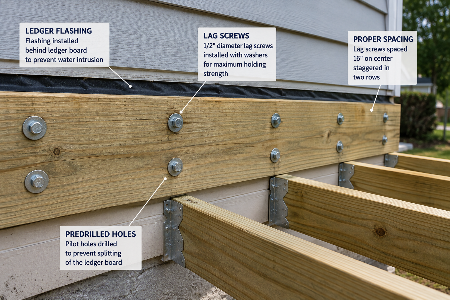
Ledger attachment is one of the most safety-critical uses of lag screws and follows specific code requirements rather than general judgment.
IRC ledger fastener requirements
The IRC deck provisions contain specific ledger fastener requirements, including fastener diameter, spacing based on joist span and load, and predrilling requirements before lag screw installation. The IRC requires lag screws 1/2 inch and larger to be predrilled to avoid wood splitting, citing NDS guidance. A current 2024 IRC-based deck guide emphasizes that inadequate house attachment is a major deck safety concern and specifies non-corrosive lag screws or through-bolts for these connections. Never assume a generic lag screw size is adequate for a ledger without following the applicable code spacing table.
Lag Screw Size for Structural Wood Connections
Diameter alone does not establish connection capacity; wood species, penetration, load direction, and fastener spacing all factor into actual design capacity.
The USDA Forest Products Laboratory provides lag screw withdrawal design values as a function of wood specific gravity and lag screw shank diameter, demonstrating why a simple diameter-only capacity table is inadequate for structural design. Edge distance, end distance, and the number of fasteners in a connection pattern also directly affect the connection’s actual capacity.
Equipment for Your Project
Affiliate disclosure: As an Amazon Associate, ConcreteCalculate earns from qualifying purchases. We may also earn a commission from other affiliate links at no additional cost to you.
Lag Screw Withdrawal Capacity
Withdrawal is the force required to pull a lag screw directly out of the wood along its axis, influenced by several interacting factors.
| Factor | Effect on Withdrawal |
|---|---|
| Screw diameter | Larger diameter generally increases withdrawal resistance |
| Threaded penetration | Greater threaded engagement increases resistance |
| Wood specific gravity | Denser wood species provide greater withdrawal resistance |
| Moisture content | Can affect long-term withdrawal performance |
Lag Screw Shear Capacity
Shear (lateral) loading pushes members to slide past each other across the fastener, a fundamentally different loading mode than withdrawal.
Single-shear connections involve two members with the load path crossing one shear plane at the fastener, while double-shear connections involve three members and two shear planes. Wood bearing capacity around the fastener and the fastener’s own bending resistance both factor into lateral load capacity, along with the overall connection geometry.
Lag Screw Withdrawal vs Shear
These two loading modes involve fundamentally different force directions and failure mechanisms.
| Characteristic | Withdrawal | Shear/Lateral |
|---|---|---|
| Load direction | Along the screw axis | Across the screw axis |
| Main concern | Pull-out | Sliding/lateral movement |
| Important factors | Penetration, wood density | Fastener bending, wood bearing |
| Typical application | Connections pulling apart | Members sliding past each other |
Lag Screw Penetration Depth
Adequate threaded penetration into the receiving member is necessary for withdrawal resistance, without a single universal target depth.
Penetration depth is influenced by the unthreaded shank length near the head, the overall member thickness being joined, and the need to leave tip clearance so the screw does not bottom out or split through the far side of the receiving member. Overpenetration in thin members risks breakthrough, while underpenetration reduces withdrawal capacity; the correct value depends on the specific connection design.
Lag Screw Pilot Hole Size
Two distinct hole types are typically needed for proper lag screw installation: a clearance hole and a lead hole.
| Hole Type | Purpose |
|---|---|
| Clearance hole | Drilled through the member the head bears against, sized to the shank diameter |
| Lead hole | Drilled in the receiving member for the threaded portion, sized smaller than the shank |
The IRC specifically requires lag screws 1/2 inch and larger to be predrilled to avoid wood splitting, citing NDS guidance. Correct drill sizes depend on both screw diameter and wood species/density, so a single generic drill bit size should not be used for every lag screw and wood combination.
Lag Screw Pilot Hole Chart
Lead hole size varies by wood density; hardwood requires a larger lead hole than softwood for the same lag screw diameter.
| Lag Screw Diameter | Lead Hole, Softwood | Lead Hole, Hardwood | Clearance Hole |
|---|---|---|---|
| 1/4″ | 9/64″ | 11/64″ | 1/4″ |
| 5/16″ | 13/64″ | 15/64″ | 5/16″ |
| 3/8″ | 15/64″ | 17/64″ | 3/8″ |
| 7/16″ | 19/64″ | 21/64″ | 7/16″ |
| 1/2″ | 11/32″ | 3/8″ | 1/2″ |
| 5/8″ | 7/16″ | 15/32″ | 5/8″ |
| 3/4″ | 35/64″ | 37/64″ | 3/4″ |
| 7/8″ | 21/32″ | 11/16″ | 7/8″ |
| 1″ | 3/4″ | 25/32″ | 1″ |
These are common industry reference lead hole sizes, generally tracking near the thread root diameter for hardwood and slightly smaller for softwood to improve thread grip. Confirm against manufacturer or project-specific guidance for critical structural connections.
Lag Screw Washers
Washers distribute the bearing load from the screw head over a larger surface area, reducing the risk of the head pulling through the wood.
A washer sized appropriately to the lag screw diameter increases the effective bearing area under the head, which is particularly important in softer wood species or higher-load connections where head pull-through could otherwise occur. For structural connections, use the washer type and dimensions required by the applicable design standard, code, or manufacturer specification, rather than an arbitrary washer size.
Lag Screw Installation Procedure
A practical installation sequence, with correct tightening rather than maximum tightening as the goal.
Select correct screw
Confirm diameter and length for the specific connection.
Confirm material compatibility
Check corrosion resistance against wood treatment and exposure.
Mark location
Position within required edge and end distances.
Drill pilot/clearance holes
Use appropriate sizes for the screw diameter and wood species.
Position members and install washer
Ensure proper alignment before driving.
Drive and tighten appropriately
Snug the connection without overdriving or splitting the wood; avoid simply tightening to maximum force.
Inspect for splitting or damage
Check the connection after installation before proceeding.
Lag Screw vs Structural Wood Screw
Structural wood screws are tested and evaluated for specific applications, so they should not be treated as interchangeable with ordinary lag screws.
| Feature | Traditional Lag Screw | Structural Wood Screw |
|---|---|---|
| Installation | Usually predrilled | Often designed for easier installation |
| Head | Hex/square | Product-specific |
| Design values | Connection/design standard (NDS) | Product-specific tested values |
| Pilot hole | Often important, especially 1/2 in.+ | Product-specific, often minimal |
| Applications | Heavy wood fastening | Engineered structural connections |
Lag Screw vs Bolt
The fundamental difference is how the fastener engages the material: threading directly into wood versus passing through with a nut.
| Feature | Lag Screw | Bolt |
|---|---|---|
| Engagement | Threads directly into wood | Passes through, secured with a nut |
| Access needed | One side only | Both sides for nut installation |
| Hole requirement | Pilot/lead hole in receiving member | Through-hole in all members |
Lag Screw vs Wood Screw
Lag screws are substantially larger and intended for heavier connections than typical wood screws.
| Feature | Lag Screw | Wood Screw |
|---|---|---|
| Typical diameter | 1/4″ and larger | Often smaller, gauge-based sizing |
| Head/drive | Hex or square, wrench driven | Screwdriver/bit driven |
| Typical application | Heavy structural wood connections | General woodworking, cabinetry |
For general wood screw dimensional reference, see the Wood Screw Size Chart.
Lag Screw vs Deck Screw
These serve entirely different roles in deck construction and should never be substituted for each other.
Do not substitute a deck screw for a structural lag screw
Deck screws attach decking boards to joists, a light-duty connection. Lag screws are larger wood-threaded fasteners used for heavier structural connections like ledgers, beams, and posts. Structural wood screws are a third, engineered/tested category for specific structural applications. Confusing these three categories, especially substituting a small deck screw for a structural fastener, can create a genuine safety hazard.
See the Deck Screw Size Chart for board-fastening screw sizing, which is a distinct topic from the structural lag screw sizing on this page.
Lag Screw Size Worked Examples
These examples are educational, not structural engineering approval for any specific project.
Reading a 1/2″ x 6″ Lag Screw Designation
Selecting Length for a Wood-to-Wood Connection
Determining Required Penetration
Choosing a Pilot-Hole Approach
Lag Screw Size and Metric Conversion
Approximate metric equivalents are useful for reference but do not represent a standardized metric substitute.
| Inch Diameter | Decimal (in.) | Approx. Metric (mm) |
|---|---|---|
| 3/8″ | 0.375 | 9.53 |
| 1/2″ | 0.500 | 12.70 |
| 5/8″ | 0.625 | 15.88 |
Approximate equivalent is not a standardized substitute
A 1/2 inch lag screw (12.7 mm) is not automatically replaceable with a 12 mm metric screw. Metric lag screws follow their own separate dimensional standards with different thread pitches and head dimensions, so approximate millimeter conversions should be used for reference only, not as a basis for direct substitution.
Lag Screw Standards and Design References
Four authoritative sources cover different aspects of lag screw dimensions, design, and application.
| Reference | Scope |
|---|---|
| ASME B18.2.1 | Square, Hex, Heavy Hex, and Askew Head Bolts and Hex, Heavy Hex, Hex Flange, Lobed Head, and Lag Screws, Inch Series; dimensional requirements for lag screws |
| NDS (National Design Specification for Wood Construction) | Structural wood connection design, including lag screw design values |
| USDA Forest Products Laboratory | Lag screw withdrawal values and wood-species-specific design considerations |
| IRC | Residential deck construction provisions where lag screws are used, including ledger fastener requirements |
The current ASME listing for this standard is B18.2.1-2012 (R2021); confirm the specific edition referenced by your project specifications.
Lag Screw Size Chart Limitations
This chart is a dimensional reference tool. It does not establish structural connection capacity.
Diameter does not determine capacity by itself
Capacity depends on many additional factors beyond diameter.
Length does not determine capacity by itself
Actual penetration and member thickness both matter.
Wood species and density matter
Withdrawal and shear values vary significantly by specific gravity.
Load direction, edge/end distance, and fastener count matter
All directly affect actual connection performance.
Structural applications may require engineering
This chart does not replace a qualified structural design.
Common Lag Screw Sizing and Installation Mistakes
The most frequent errors in lag screw selection and installation.
Using the wrong diameter
Undersized fasteners reduce connection capacity below design requirements.
Choosing excessive length
Can cause breakthrough or unnecessary material cost.
Insufficient penetration
Reduces withdrawal resistance below design intent.
No pilot hole where one is needed
Can cause wood splitting, especially at 1/2 in. and larger.
Wrong pilot-hole diameter
Too small causes splitting; too large reduces holding power.
Installing too close to an edge or end
Increases splitting risk and reduces connection capacity.
Using ordinary screws for structural connections
Deck screws and general wood screws are not rated for structural loads.
Using incompatible coatings
Standard coatings can corrode prematurely with treated lumber.
Confusing lag screws with bolts or structural wood screws
Each category has distinct design values and installation requirements.
Frequently Asked Questions
Download Lag Bolt Sizes Chart PDF
Use your browser’s print function to save a curated, print-ready reference sheet: the quick-reference chart, diameter/length/TPI tables, socket size chart, pilot hole chart, and diagrams, without navigation, FAQs, or explanatory prose. This avoids broken file links and stays automatically current.