Sleeve Anchor Size Chart: Diameter, Drill Bit, Length & Embedment
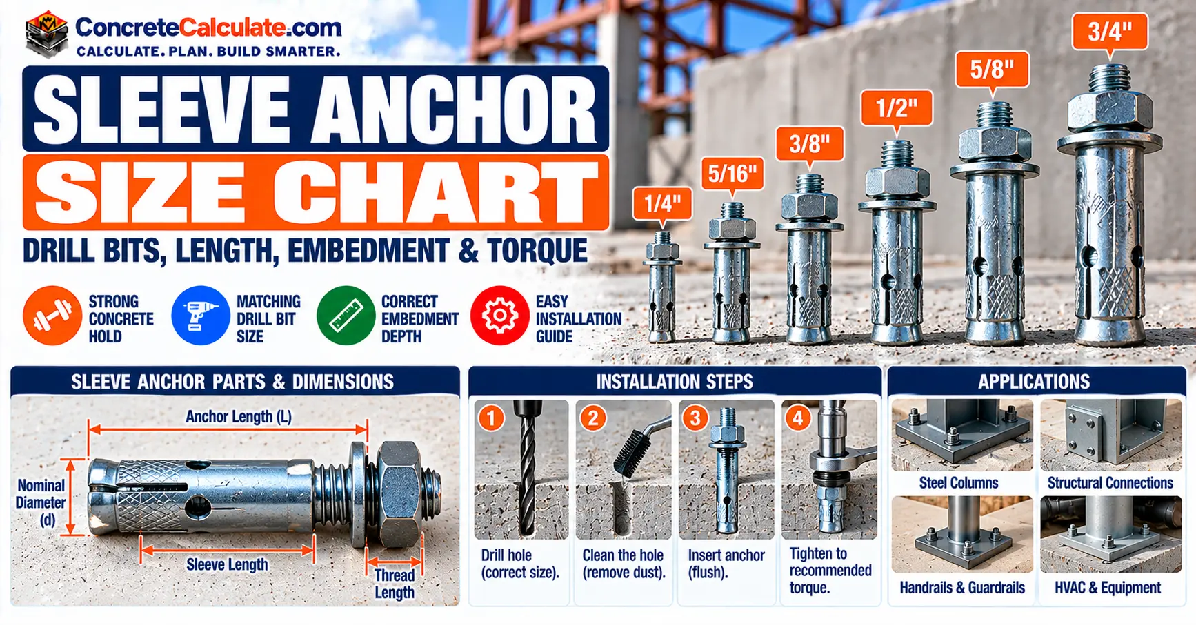
Sleeve Anchor Size Chart: Diameter, Drill Bit, Length & Embedment
Six sleeve anchor sizes with matching drill bits, internal bolt diameters, minimum embedment, installation torque, fixture thickness and the limits of manufacturer-specific data.
 Reviewed by Muhammad Ramzan Babar, PhD Researcher (Plasma Physics) & Calculator Developer. View Profile
Key Facts
- Nominal sleeve diameter is not the internal bolt diameter. A 1/2 in. Dynabolt uses a 1/2 in. drill bit and has a 3/8 in. internal bolt.
- Minimum embedment and installation torque are product-specific. For ITW Dynabolt, 3/8 in. needs 1-1/2 in. embedment and 14 ft-lb in normal-weight concrete, while Simpson Sleeve-All lists 15 ft-lb.
- Anchor length, fixture thickness and embedment are different measurements, and load capacity cannot be read from diameter alone.
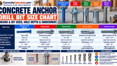
- For drill bits across anchor types, see the Concrete Anchor Drill Bit Size Chart and the Wedge Anchor Size Chart.
Sleeve Anchor Size Chart: Quick Reference
Diameter, drill bit, internal bolt, embedment and torque for six sizes, with the manufacturer named.
How to Read This Chart
Read across a row from the nominal sleeve diameter to the matching carbide drill bit, the smaller internal bolt diameter, the minimum embedment and the installation torque. Example: a 3/8 in. Dynabolt uses a 3/8 in. drill bit, has a 5/16 in. internal bolt, needs 1-1/2 in. minimum embedment and is tightened to 14 ft-lb in normal-weight concrete.
| Nominal sleeve diameter | Drill bit | Internal bolt diameter | Minimum embedment | Installation torque |
|---|---|---|---|---|
| 1/4 in. | 1/4 in. | 3/16 in. | 1-1/8 in. | 3.5 ft-lb |
| 5/16 in. | 5/16 in. | 1/4 in. | 1-1/4 in. | 8 ft-lb |
| 3/8 in. | 3/8 in. | 5/16 in. | 1-1/2 in. | 14 ft-lb |
| 1/2 in. | 1/2 in. | 3/8 in. | 1-7/8 in. | 20 ft-lb |
| 5/8 in. | 5/8 in. | 1/2 in. | 2 in. | 48 ft-lb |
| 3/4 in. | 3/4 in. | 5/8 in. | 2-1/4 in. | 90 ft-lb |
Dynabolt Reference Values, Not Universal Specifications
Nominal sleeve diameter is not the internal bolt diameter. Drill-bit dimensions must match the selected product’s instructions, and installation torque depends on the product, the base material and the application. Minimum embedment is not the minimum drilled-hole depth. Load ratings need separate, product-specific verification, and nothing here extends to cracked concrete or seismic applications.
Anchor Diameter and Drill Bit
For the Dynabolt and Simpson Sleeve-All families, the carbide drill bit has the same nominal diameter as the anchor. For a comparison across anchor types, see the Concrete Anchor Drill Bit Size Chart.
Internal Bolt Diameter
The internal bolt is smaller than the sleeve, so never pick a drill bit from the bolt size.
Minimum Embedment and Torque
Both are tied to the product family and the base material. Compare manufacturers in the torque section below.
What Is a Sleeve Anchor?
A post-installed mechanical expansion fastener.
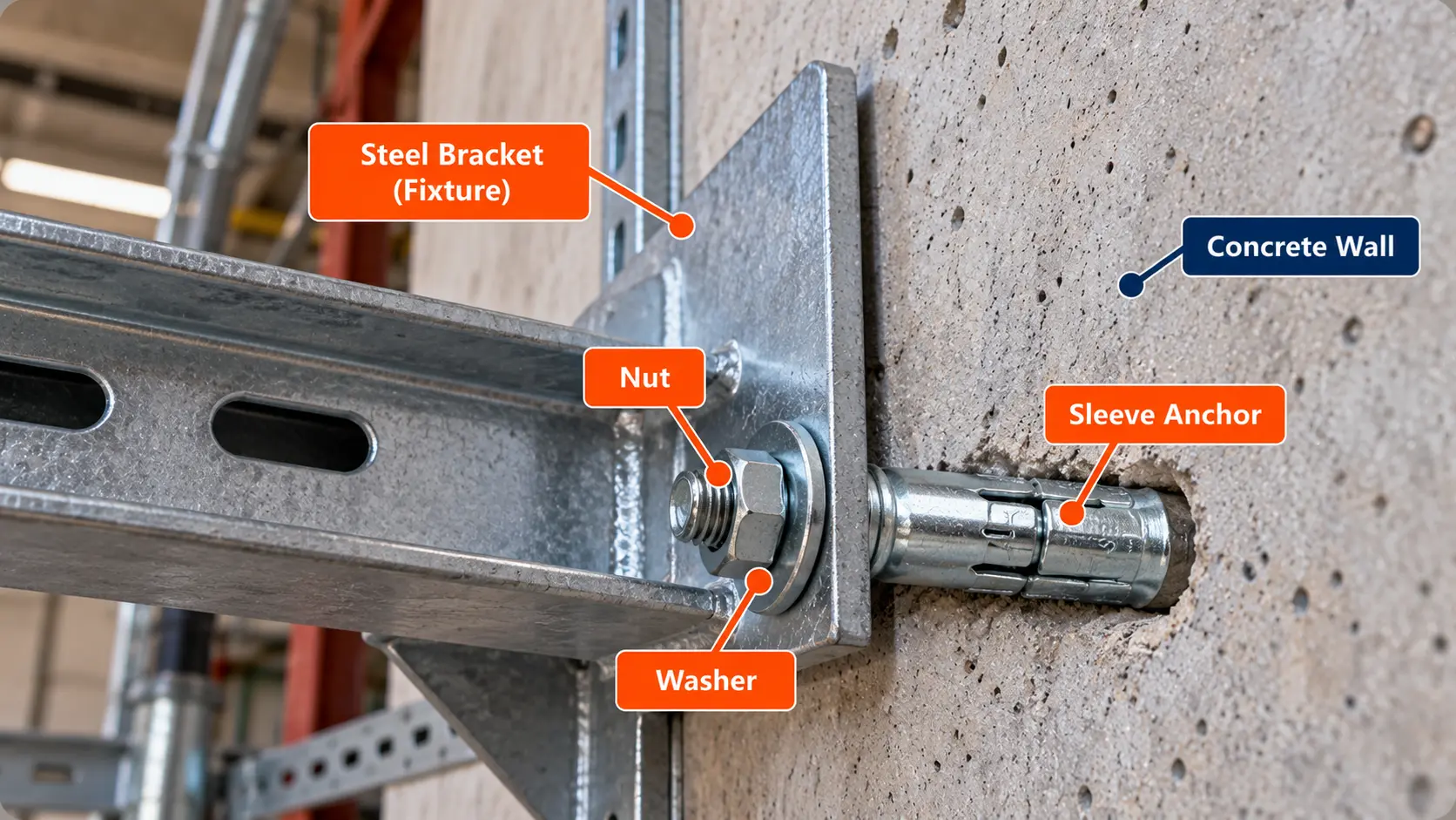
A sleeve anchor is a post-installed mechanical expansion fastener. ITW describes the Dynabolt as a split expansion sleeve over a threaded stud body with an integral expander, nut and washer. Tightening the nut or head draws the cone into the sleeve, which presses the sleeve against the hole wall.
How Sleeve Anchors Work
The anchor is installed through the fixture into a hole drilled to the anchor’s nominal diameter. Tightening the nut 2 to 3 turns expands the sleeve (ITW installation step). The expansion is concentrated near the cone end, not uniform along the sleeve.
Common Applications
Manufacturer-listed uses include electrical junction boxes, conduit, shelf ledgers and light brackets in concrete, block and brick. Sleeve anchors are not wedge anchors. They share the idea of mechanical expansion but differ in components and requirements, as the comparison below shows.
Sleeve Anchor Parts and Dimensions
Why the anchor name does not equal the bolt size.
Seven dimensions and parts show up in every sleeve anchor discussion.
| Item | What it is |
|---|---|
| Outer sleeve diameter | Nominal size of the anchor and of the drill bit |
| Internal bolt or stud diameter | Smaller threaded stud inside the sleeve |
| Expansion sleeve and cone | Split sleeve pushed outward by a tapered cone |
| Threaded section and nut | Where torque is applied to expand the anchor |
| Washer | Bears on the fixture |
| Anchor length | Measured per the manufacturer’s definition |
| Installed embedment | Depth the anchor reaches into the base material |
Expansion Sleeve and Cone
The sleeve is the part that touches the hole wall. For the Dynabolt it provides contact over a large area of the hole wall.
Bolt, Nut and Washer
See the Nut Size Chart and Washer Size Chart for general hardware dimensions.
Nominal Diameter vs. Bolt Diameter
They are different numbers. The nominal diameter names the anchor and the drill bit, and the bolt diameter is smaller.
Standard Sleeve Anchor Diameters
Six inch diameters, with availability by product family.
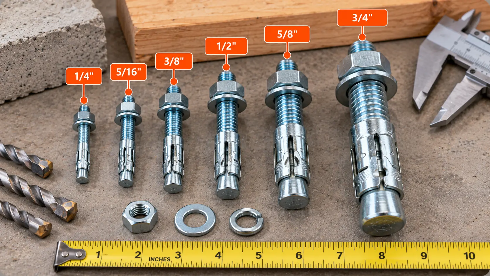
Inch-series sleeve anchors come in six nominal diameters: 1/4, 5/16, 3/8, 1/2, 5/8 and 3/4 in. Not every manufacturer supplies all six, and lengths, head styles and materials vary.
Fractional and Decimal Sizes and Metric Conversions
| Nominal diameter | Decimal inches | Millimeters |
|---|---|---|
| 1/4 in. | 0.2500 | 6.35 |
| 5/16 in. | 0.3125 | 7.94 |
| 3/8 in. | 0.3750 | 9.53 |
| 1/2 in. | 0.5000 | 12.70 |
| 5/8 in. | 0.6250 | 15.88 |
| 3/4 in. | 0.7500 | 19.05 |
Manufacturer Size Availability
| Manufacturer and product | Inch sizes noted in published data |
|---|---|
| ITW Red Head Dynabolt | 1/4, 5/16, 3/8, 1/2, 5/8, 3/4 |
| Simpson Strong-Tie Sleeve-All | 1/4, 5/16, 3/8, 1/2, 5/8, 3/4 |
| DEWALT Lok-Bolt AS | 1/4, 5/16, 3/8, 1/2, 5/8, 3/4 |
| Hilti HLC-H (hex head) | 5/16, 3/8, 1/2 |
Sleeve Anchor Drill Bit Size Chart
Match the nominal anchor diameter with a carbide bit made to ANSI B212.15.
ITW and Simpson both tell installers to use a carbide-tipped bit whose diameter equals the nominal anchor diameter. For inch-series products the bit is made to ANSI B212.15, which sets the finished hole diameter range. A 3/8 in. sleeve anchor takes a 3/8 in. carbide masonry bit. Do not extend this rule to concrete screws, adhesive anchors or other expansion systems. For those, see the Concrete Anchor Drill Bit Size Chart and the general Drill Bit Size Chart.
Matching Drill Diameters and ANSI B212.15 Tolerances
| Sleeve anchor | Nominal drill bit | Finished hole minimum (in.) | Finished hole maximum (in.) |
|---|---|---|---|
| 1/4 in. | 1/4 in. | 0.260 | 0.268 |
| 5/16 in. | 5/16 in. | 0.327 | 0.335 |
| 3/8 in. | 3/8 in. | 0.390 | 0.398 |
| 1/2 in. | 1/2 in. | 0.520 | 0.530 |
| 5/8 in. | 5/8 in. | 0.650 | 0.660 |
| 3/4 in. | 3/4 in. | 0.775 | 0.787 |
Hole Tolerances
A properly sized hole is critical to anchor performance. A worn bit can drill an undersized hole, and an oversized hole lets the sleeve expand without a firm grip. Rotary-hammer drills with light, high-frequency impact are recommended. In archaic or hollow base materials, set the drill to rotation-only mode.
Sleeve Anchor Diameter vs. Bolt Diameter
Outside sleeve diameter against the internal bolt size.
The outer sleeve diameter names the anchor. The internal bolt is a size smaller, as the ITW table shows.
| Nominal sleeve and drill bit | Internal bolt diameter |
|---|---|
| 1/4 in. | 3/16 in. |
| 5/16 in. | 1/4 in. |
| 3/8 in. | 5/16 in. |
| 1/2 in. | 3/8 in. |
| 5/8 in. | 1/2 in. |
| 3/4 in. | 5/8 in. |
Worked Identification Example
Identify a 1/2 in. Dynabolt
What it means: Do not choose the drill bit from the 3/8 in. bolt size. A 3/8 in. bit would be too small for the sleeve.
Sleeve Anchor Length Chart
Real Dynabolt models with their lengths, embedments and fixture limits.
Effective anchor length is not the same as overall length or sleeve length, and every manufacturer defines length in its own way. The table uses ITW Dynabolt hex-nut models in zinc-plated carbon steel, where effective length is measured as ITW defines it and the stated maximum fixture thickness is the published value for that model. Avoid mixing lengths from different manufacturers.
| Part no. | Anchor diameter and drill bit (in.) | Effective anchor length (in.) | Bolt diameter / TPI | Minimum embedment (in.) | Maximum fixture thickness (in.) |
|---|---|---|---|---|---|
| HN-1614 | 5/16 | 1-1/2 | 1/4 / 20 | 1-1/4 | 1/4 |
| HN-3817 | 3/8 | 1-7/8 | 5/16 / 18 | 1-1/2 | 3/8 |
| HN-3830 | 3/8 | 3 | 5/16 / 18 | 1-1/2 | 1-1/2 |
| HN-1222 | 1/2 | 2-1/4 | 3/8 / 16 | 1-7/8 | 3/8 |
| HN-1230 | 1/2 | 3 | 3/8 / 16 | 1-7/8 | 1-1/8 |
| HN-1240 | 1/2 | 4 | 3/8 / 16 | 1-7/8 | 2-1/8 |
| HN-5830 | 5/8 | 3 | 1/2 / 13 | 2 | 1 |
| HN-5842 | 5/8 | 4-1/4 | 1/2 / 13 | 2 | 2-1/4 |
| HN-3440 | 3/4 | 4 | 5/8 / 11 | 2-1/4 | 1-3/4 |
Anchor Length, Fixture Thickness and Product Examples
Notice the pattern in the table: effective length minus minimum embedment equals the maximum fixture thickness, for example 4 − 1-7/8 = 2-1/8 in. for the HN-1240. That relationship is the basis for the length calculation in the next section.
How to Select Sleeve Anchor Length
Fixture thickness plus embedment, checked against the product table.
A preliminary check compares the effective length with the fixture thickness plus the required embedment. The manufacturer’s published maximum fixture thickness is the authority.
🧮 Preliminary Length Check
Variables: Leffective = effective anchor length, tf = fixture thickness, hnom = nominal embedment required by the product. This is a geometric check only.
Maximum Fixture Thickness
Read it straight from the product table. Do not assume a universal relationship across brands.
Worked Selection Example
Choosing a 1/2 in. Dynabolt for a 1-1/2 in. Fixture
What it means: This is only a dimensional selection. It does not approve the anchor’s load capacity, edge distance, base material or installation conditions.
Sleeve Anchor Minimum Embedment Chart
Product-specific depths from the Dynabolt data.
Minimum embedment is product-specific. Simpson defines nominal embedment as the distance from the base material surface to the installed end of the anchor, measured before torque is applied, and effective embedment as the distance to the deepest point where load is transferred. ITW publishes the minimum embedment for each Dynabolt diameter, and it can change with the base material.
| Anchor diameter | Solid and lightweight concrete (in.) | Concrete masonry units (in.) |
|---|---|---|
| 1/4 in. | 1-1/8 | 1-1/8 |
| 5/16 in. | 1-1/4 | not tabulated |
| 3/8 in. | 1-1/2 | 1-1/2 |
| 1/2 in. | 1-7/8 | 1-7/8 |
| 5/8 in. | 2 | 2 |
| 3/4 in. | 2-1/4 | 2-1/2 |
Minimum, Nominal and Effective Embedment
Do not use one term for another. Deeper embedment does not automatically raise load resistance in proportion, and the base material must be thick enough for the depth.
Base Material Requirements
Check the thickness of the concrete or masonry against the product data. See the section on concrete thickness below.
Sleeve Anchor Hole Depth vs. Embedment
Drilling to the embedment depth alone can be too shallow.
Drilled-hole depth and embedment are different numbers. The hole needs room for the full embedment and for the dust that settles at the bottom. ITW says to drill the hole to any depth exceeding the minimum embedment and to clean it. Simpson says to drill to the specified embedment depth and blow the hole clean with compressed air (overhead installations need not be blown clean), or alternatively to drill deep enough to hold both the embedment and the dust.
| Term | Meaning |
|---|---|
| Embedment | Depth of the anchor in the base material |
| Drilled-hole depth | Depth of the hole, deeper than the embedment |
| Hole-bottom clearance | Extra depth that holds dust and keeps the cone from bottoming |
| Fixture thickness | Material between the nut and the concrete surface |
Cleaning Requirements
Use the manufacturer’s instruction for cleaning. Do not apply a universal overdrill allowance, because the allowance comes from the selected product.
Sleeve Anchor Installation Torque Chart
Torque comes from the product, and sometimes the base material.
Sleeve anchors are torque-controlled. Under-tightening can leave the sleeve unexpanded and the anchor loose, and over-tightening can damage the base material or the anchor. Simpson warns that failing to apply the required installation torque can cause excessive displacement or premature failure, and that expansion anchors lose some pre-tension after setting. Use a torque wrench and the selected product’s instructions.
| Nominal diameter | ITW Dynabolt (ft-lb) | Simpson Sleeve-All (ft-lb) |
|---|---|---|
| 1/4 in. | 3.5 | 5 |
| 5/16 in. | 8 | 8 |
| 3/8 in. | 14 | 15 |
| 1/2 in. | 20 | 25 |
| 5/8 in. | 48 | 50 |
| 3/4 in. | 90 | 90 |
Torque Comparison
The values differ between manufacturers for the same diameter, which is why torque must come from the selected product. Hilti HLC and DEWALT Lok-Bolt AS have their own instructions. For general torque concepts, see the Bolt Torque Chart.
Torque Can Vary With Base Material
| Diameter | Normal-weight concrete (ft-lb) | Lightweight concrete (ft-lb) | Concrete masonry units (ft-lb) |
|---|---|---|---|
| 3/8 in. | 14 | 14 | 15 |
| 1/2 in. | 20 | 25 | 25 |
| 5/8 in. | 48 | 48 | 55 |
| 3/4 in. | 90 | 90 | 90 |
No Generic Torque Formula
Do not use a general T = K × F × d formula to set sleeve anchor torque. The manufacturer’s published torque already accounts for the anchor’s friction and expansion.
Sleeve Anchor Head Styles
How the head changes clearance and use.
Head style changes fixture clearance, appearance and tool choice. ITW lists hex nut (HN) and Phillips flat head (FS) models in its Dynabolt product data, with flat heads designed for a standard 80 to 82 degree countersink, and Simpson supplies hex-head, acorn-head and Phillips flat head styles of Sleeve-All. Other styles exist, and availability varies by product, diameter and base material.
| Head style | Common purpose | Important consideration |
|---|---|---|
| Hex nut | General fastening and brackets | Nut and washer arrangement |
| Hex bolt head | Fastening with a wrench or socket | Head and fixture clearance |
| Acorn nut | Finished exposed appearance | Product-specific dimensions |
| Flat head | Flush or countersunk installation | Correct countersink geometry (80 to 82 degrees for Dynabolt) |
| Round head | Selected light-duty fixtures | Driver type |
| Tie-wire head | Specific suspended attachments | Approved load direction and product rating |
Hex Nut and Hex Head
The most common styles. A wrench size table for each product shows the tool needed.
Flat and Acorn Heads, and Special Configurations
Flat heads sit flush, acorn nuts give a finished look, and tie-wire heads are for specific suspended attachments with a rated load direction.
Sleeve Anchors for Concrete
Strength, cracking and qualification.
A sleeve anchor advertised for concrete is not automatically qualified for every structural application. Resistance depends on the concrete strength, whether the concrete is cracked, the embedment, the edge distance, the member thickness and the loading direction. Simpson also advises that mechanical anchors should not be installed in concrete younger than 7 days, and that anchors installed in concrete younger than 28 days should be rated by the concrete’s actual compressive strength at installation. See the Concrete PSI Chart and the Concrete Strength Gain Chart.
Normal-Weight Concrete
ITW publishes Dynabolt ultimate values in normal-weight concrete at 2,000, 3,000 and 4,000 psi, and separate values for lightweight concrete. Tests follow ASTM E488.
Cracked vs. Uncracked Concrete
ACI 355.2 sets criteria for deciding whether a post-installed mechanical anchor is acceptable for uncracked concrete only, or for cracked and uncracked concrete. ACI 355.2 applies to expansion, undercut and screw anchors with a minimum effective embedment of 1-1/2 in. and a nominal diameter of 1/4 in. or larger. Shallow anchors below that depth fall outside its scope. Qualification belongs to the specific anchor and is documented in an evaluation report. Not every economical sleeve anchor is evaluated for cracked concrete, seismic loads or safety-critical use.
Concrete Strength
A higher strength usually raises the published ultimate values, as the 3/8 in. Dynabolt example below shows.
Sleeve Anchors for Brick and Masonry
Not every sleeve anchor or every diameter is approved for every masonry unit.
ITW specifies the Dynabolt for anchorage into concrete, grout-filled concrete block, hollow concrete block and brick. Hilti and DEWALT sleeve anchors also list masonry uses with product-specific limits. Performance in solid concrete cannot be carried over to hollow block or brick.
| Anchor diameter | Hollow-core CMU | Grout-filled CMU |
|---|---|---|
| 1/4 in. | Tabulated | Tabulated |
| 3/8 in. | Tabulated | Tabulated |
| 1/2 in. | N/A (not advisable) | Tabulated |
| 5/8 in. | N/A (not advisable) | Tabulated |
| 3/4 in. | N/A (not advisable) | Tabulated |
Solid Brick and Solid CMU
Solid brick and solid units behave differently from hollow units. Sound, solid material is a requirement, and weak or deteriorated masonry is not suitable.
Hollow and Grout-Filled CMU
In hollow units the anchor bears on thin face shells, so larger diameters may not be advisable. Set the drill to rotation-only mode in hollow base materials, and do not install into mortar joints without the manufacturer’s approval.
Sleeve Anchor Load Capacity
Ultimate values, allowable values and why they differ.
Ultimate loads are the loads at failure in the manufacturer’s tests. Allowable loads divide those values by a safety factor, which ITW sets at 4 to 1 in its tables. Strength-design values under ACI 318 are a different framework, so manufacturer allowable tables are not automatically ACI design strengths. Failure modes include steel failure, pullout, concrete breakout and masonry failure.
| Concrete strength | Ultimate tension (lb) | Ultimate shear (lb) |
|---|---|---|
| 2,000 psi | 1,620 | 2,560 |
| 3,000 psi | 2,240 | 2,800 |
| 4,000 psi | 3,100 | 3,040 |
Worked Manufacturer Example
Allowable Tension for a 3/8 in. Dynabolt
What it means: These are not universal allowable sleeve anchor loads. The base material, embedment, edge distance, spacing and loading direction must all satisfy the table conditions. Combined loads use the interaction equation (Ps/Pt) + (Vs/Vt) ≤ 1 from the same manufacturer data.
Ultimate Is Not Allowable
Never treat an ultimate load as an allowable load, and never create a generic weight-capacity chart by diameter. Historical manufacturer allowable tables differ from evaluated strength-design data.
Sleeve Anchor Spacing Requirements
Anchors need room from each other and from edges.
Spacing is the center-to-center distance between anchors. Edge distance is measured from the anchor center to the free edge. Anchors installed too close together, or too near an edge, share or lose concrete and can fail at a lower load. Use only the selected product’s approved values, and do not publish a universal rule such as 6d or 10d as a guaranteed sleeve anchor minimum.
Minimum Spacing and Anchor Group Effects
As one example of product-specific data, ITW’s concrete masonry table states that the tabulated values assume anchors at least 12 diameters on center with a 6-diameter edge distance for full efficiency, and that values are reduced by 50 percent if spacing and edge distance are cut to 6 and 3 diameters, with linear interpolation between. Other base materials and products have their own values. For cast-in-place foundation anchors, see the Anchor Bolt Spacing Chart, but note that its rules are not universal sleeve anchor requirements.
Product-Specific Limits
Read the spacing and edge-distance notes on the table you use.
Sleeve Anchor Edge Distance
Why a correctly drilled hole near an edge can still fail.
Edge distance matters because the concrete cone that breaks out near an anchor is cut short at a free edge, and the anchor’s expansion force can split thin edges. Corners and thin members are worst. Reduced capacity at small edge distances is built into product tables, as the ITW footnote above shows.
Edge Distance Measurement and Concrete Breakout
Measure from the center of the anchor to the nearest free edge. The nearest edge in any direction governs.
Reduced Capacity
Where the distance falls below the full-capacity value, capacity drops according to the product data, and below the minimum edge distance the anchor should not be used.
Sleeve Anchor Concrete Thickness
The anchor fitting does not mean the concrete is thick enough.
A sleeve anchor must have enough base material around and below it. Embedment depth, minimum member thickness and the remaining concrete below the hole are three different things. Do not assume an anchor suits a thin slab just because it physically fits. Simpson notes that anchoring into members thinner than its catalog recommends needs a qualified designer’s evaluation.
| Check | Why it matters |
|---|---|
| Embedment depth | Sets how far the anchor reaches into the base material |
| Minimum member thickness | Published by the manufacturer for the anchor and base material |
| Remaining concrete below the hole | Thin remaining material reduces breakout resistance |
| Through-drilling | Drilling through a slab may be prohibited or need approval |
| Masonry face shells | Hollow units have thin walls that govern capacity |
Thin Slabs and Walls
Check the manufacturer’s minimum thickness for each diameter and embedment, and locate reinforcement before drilling (see the Concrete Cover Chart for cover context). Do not drill through a slab-on-ground or a slab with post-tension tendons or embedded items without approval.
Sleeve Anchor Materials and Corrosion Protection
Match the anchor material to the exposure.
Sleeve anchors are supplied in zinc-plated carbon steel and 304 stainless steel. ITW lists the zinc-plated Dynabolt for interior, non-corrosive environments with a low corrosion level (shelf ledgers, electrical boxes, conduit) and the stainless steel Dynabolt for slight to moderate pollution with a medium level of corrosion (cladding and brick ties). Hilti’s HLC-H hex head sleeve anchor is carbon steel, zinc-plated, for indoor, dry conditions.
| Material | Typical exposure (manufacturer guidance) | Limit |
|---|---|---|
| Zinc-plated carbon steel | Interior, dry, non-corrosive | Not for coastal, marine or severe outdoor exposure |
| 304 stainless steel | Slight to moderate pollution | Check the environment, including chlorides |
| Other manufacturer-approved finishes | Per the manufacturer | Check product data |
Zinc-Plated Carbon Steel and Stainless Steel
Simpson also notes that some hardened fasteners may fail early if exposed to moisture and are for dry interior use. Zinc-plated anchors should not be assumed suitable outdoors. Also consider dissimilar-metal contact with the fixture.
How to Install a Sleeve Anchor
Drill, clean, insert, tighten and inspect.
The installation instructions for the product override generic practice. Installation tests are run with anchors within about 6 degrees of perpendicular, and tilting an anchor can reduce its capacity.
- Confirm the specified anchor product and its instructions.
- Check the base material (strength, soundness, age).
- Mark the hole location.
- Verify spacing and edge distance against the product data.
- Select the carbide bit that matches the nominal anchor diameter.
- Drill to the specified hole depth, perpendicular to the surface.
- Clean the hole as instructed.
- Insert the anchor through the fixture (or as specified) and drive it until the washer or head is flush.
- Tighten to the specified torque. ITW expands the anchor with 2 to 3 turns of the nut.
- Inspect the installation.
Drilling and Hole Cleaning, Insertion, and Tightening
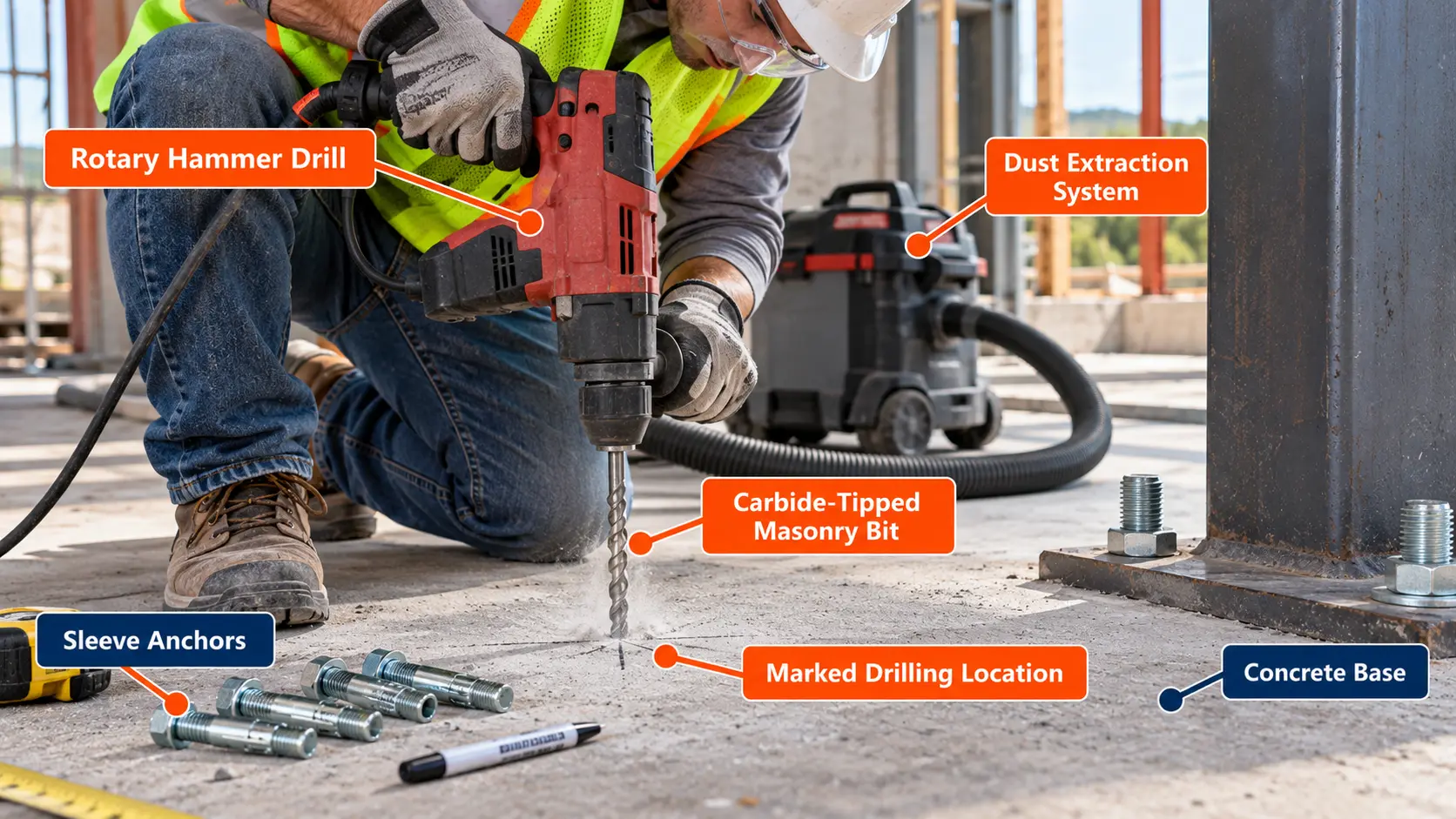
Use a rotary hammer with light, high-frequency impact, eye protection and dust control.
Sleeve Anchor vs. Wedge Anchor
Related, but not interchangeable.
Both are mechanical expansion anchors, but they are not the same product, and a sleeve anchor and a wedge anchor of the same diameter do not carry the same load. See the Wedge Anchor Size Chart for wedge anchor data.
| Topic | Sleeve anchor | Wedge anchor |
|---|---|---|
| Expansion mechanism | Split sleeve expanded by a cone as the nut is tightened | Expansion clip driven up a tapered end of the stud |
| Base materials | Concrete, grout-filled and hollow block, brick (product-specific) | Mainly concrete |
| Drill bit | Matches nominal anchor diameter (Dynabolt and Sleeve-All) | Per wedge anchor product data |
| Qualification | Varies; many are not qualified for cracked concrete | Many wedge anchors are qualified, check the report |
| Typical use | Light to medium fixtures | Medium to heavy fixtures |
Expansion Mechanisms, Sizing and Application Differences
Do not assume equal capacity for equal diameters. Compare the exact products.
Sleeve Anchor vs. Drop-In and Concrete Screw Anchors
Four ways to anchor to concrete and masonry.
Other anchor types solve different problems. Keep detailed drilling comparisons on the Concrete Anchor Drill Bit Size Chart.
| Anchor | How it develops resistance |
|---|---|
| Sleeve anchor | Expansion of a sleeve against the hole wall |
| Drop-in anchor | Internally threaded expansion anchor set with a setting tool |
| Concrete screw | Thread engagement with the concrete (see the Concrete Screw Size Chart) |
| Adhesive anchor | Bonded anchorage system with an approved adhesive and rod |
Drop-In Anchors, Concrete Screws and Adhesive Anchors
Each has its own hole, embedment and installation rules, so do not carry values from one to another.
Common Sleeve Anchor Applications
Light-duty fixtures, and where to stop.
Manufacturer-listed uses include electrical junction boxes, conduit, shelf ledgers, light brackets, signs, equipment accessories and other nonstructural attachments in concrete, block and brick.
Brackets and Fixtures
Through-fastening a bracket or ledger is the textbook sleeve anchor use, and the fixture thickness drives the length.
Safety-Critical Application Limitations
Qualification First
For railings, guardrails, overhead supports, safety-critical equipment and structural applications, use an appropriately qualified anchor selected under an engineered design. Do not choose a sleeve anchor diameter for a safety-critical application from common practice alone.
How to Choose the Correct Sleeve Anchor Size
A selection sequence, not a lookup.
Choose the product first, then the size.
- Identify the base material.
- Determine the applied loads.
- Check whether structural or seismic qualification is required.
- Choose an approved anchor family.
- Determine the required diameter.
- Check the minimum embedment.
- Select the length from the fixture thickness.
- Verify the drill bit and hole depth.
- Check spacing, edge distance and member thickness.
- Verify torque, corrosion resistance and installation instructions.
For general anchor families, see the Anchor Bolt Size Chart and Anchor Bolt Grade Chart.
Common Sleeve Anchor Mistakes
The drill-bit, embedment, torque and load errors that cause the most trouble.
Drill-bit errors
Confusing sleeve diameter with bolt diameter, selecting a drill bit from the internal bolt diameter, or using an oversized or worn bit.
Hole preparation
Ignoring hole cleaning.
Embedment and length
Using insufficient embedment, or choosing a short anchor for a thick fixture.
Torque errors
Applying the wrong installation torque.
Base material errors
Assuming all sleeve anchors work in hollow CMU, or installing in weak or deteriorated masonry.
Edge and thickness
Ignoring edge distance, or installing in concrete that is too thin.
Load errors
Treating ultimate loads as allowable loads, or using unqualified anchors in cracked concrete.
Corrosion
Assuming zinc-plated anchors are suitable outdoors.
Substitution and reuse
Substituting another brand without checking its data, reusing an expanded anchor without authorization, or assuming a removed anchor keeps its original capacity.
Sleeve Anchor Chart Limitations and Safety
Reference data is not an anchor design.
This chart does not independently establish:
- Structural anchor design strength or seismic qualification.
- Cracked-concrete approval.
- A suitable anchor count.
- Minimum concrete thickness or adequate edge distance.
- Masonry capacity.
- Acceptable corrosion exposure.
- Compliance with a specific building code.
The governing product documentation, evaluation reports (such as ICC-ES reports for a specific model), the adopted code and the project design requirements control. ACI 355.2 qualification and ACI 318 anchorage design (Chapter 17) apply to the specific anchor and the specific application. Manufacturer ultimate-load data must not be substituted directly for ACI design strengths.
Sleeve Anchor Size FAQs
Straight answers to the most common sleeve anchor questions.
What sizes do sleeve anchors come in?
Inch-series sleeve anchors come in 1/4, 5/16, 3/8, 1/2, 5/8 and 3/4 in. nominal diameters, though not every manufacturer supplies every size.
What drill bit do I need for a 1/4-inch sleeve anchor?
A 1/4 in. carbide-tipped masonry bit. For Dynabolt and Sleeve-All the bit matches the nominal anchor diameter.
What size hole does a 3/8-inch sleeve anchor need?
A 3/8 in. nominal carbide bit, which under ANSI B212.15 drills a finished hole of about 0.390 to 0.398 in.
What size drill bit fits a 1/2-inch sleeve anchor?
A 1/2 in. carbide-tipped bit. Do not use a 3/8 in. bit based on the internal bolt size.
Is sleeve anchor diameter the same as bolt diameter?
No. For the Dynabolt, a 1/2 in. sleeve anchor has a 3/8 in. internal bolt. The sleeve diameter names the anchor and sets the drill bit.
How deep should I drill for a sleeve anchor?
Deep enough for the minimum embedment plus dust space. ITW says to drill deeper than the minimum embedment and clean the hole, and Simpson says to drill to the specified embedment depth and blow it clean. Follow your product’s instructions.
What is the minimum embedment for a sleeve anchor?
It is product-specific. For ITW Dynabolt, 1/4 in. needs 1-1/8 in., 3/8 in. needs 1-1/2 in., 1/2 in. needs 1-7/8 in. and 3/4 in. needs 2-1/4 in. in concrete.
How do I choose sleeve anchor length?
Effective length must at least equal fixture thickness plus the required embedment, and the product’s maximum fixture thickness controls. A 1-1/2 in. fixture with a 1/2 in. Dynabolt points to the 4 in. HN-1240, which allows 2-1/8 in.
How much weight can a 3/8-inch sleeve anchor hold?
It depends on the product, concrete strength, embedment, edge distance, spacing and load direction. The ITW table lists 3,100 lb ultimate tension at 4,000 psi, and an allowable of 775 lb at the manufacturer’s 4:1 factor. That is not a universal rating.
Can sleeve anchors be used in brick?
Some products are specified for brick, but capacity is product-specific and the brick must be sound. Avoid mortar joints unless the manufacturer approves.
Can sleeve anchors be used in hollow concrete block?
Some can, with limits. ITW marks 1/2, 5/8 and 3/4 in. Dynabolts as not advisable in hollow-core units, so check the table.
Can sleeve anchors be used in cracked concrete?
Only if the specific anchor is qualified for it under ACI 355.2 and documented in an evaluation report. Many sleeve anchors are not.
What torque should I use?
Use the selected manufacturer’s value. For 3/8 in., ITW lists 14 ft-lb in normal-weight concrete and Simpson lists 15 ft-lb. See the Bolt Torque Chart.
Can sleeve anchors be used outdoors?
Zinc-plated sleeve anchors are for dry interior use. For outdoor exposure, check the manufacturer’s environmental guidance, and consider stainless steel.
Are sleeve anchors removable?
Some are marketed as removable for temporary fastening, such as the Hilti HLC-H, but a removed anchor generally does not keep its original capacity.
Can sleeve anchors be reused?
Do not reuse an expanded anchor unless the manufacturer authorizes it.
What is the difference between sleeve and wedge anchors?
They both expand mechanically, but the expansion components, base materials and qualifications differ. See the Wedge Anchor Size Chart.
Are sleeve anchors suitable for railings?
Railings and guardrails are safety-critical. Use an anchor qualified and designed for that load, not a sleeve anchor chosen from common practice.
How far should a sleeve anchor be from an edge?
It depends on the product and load. ITW’s masonry table assumes a 6-diameter edge distance for full values, with reductions below that. Use the data for your anchor.
Cite or Embed This Chart
📄 Print or Save This Chart as PDF
Use your browser’s print function to save the page as a PDF reference for jobsite binders and estimating folders.
Sources and Standards Used
Embedment, torque, length, fixture thickness and performance values are taken from the named manufacturer’s published data (ITW Red Head Dynabolt and Simpson Strong-Tie Sleeve-All) and apply only to those products. ANSI B212.15 hole ranges are as published by Simpson Strong-Tie. Metric conversions and the 775 lb illustration are calculated and marked as derived. Always confirm against the current product data, evaluation report and project requirements.
- ITW Red Head, Dynabolt Sleeve Anchor Technical Data
- ITW Red Head, Dynabolt Sleeve Anchor Product Data
- Simpson Strong-Tie, Sleeve-All Sleeve Anchor
- Simpson Strong-Tie, General Notes for Anchoring Systems (ANSI B212.15 hole tolerances)
- Hilti, HLC-H Sleeve Anchor
- ACI 355.2, Qualification of Post-Installed Mechanical Anchors in Concrete
- ICC Evaluation Service