PEX Pipe Size Chart – OD, ID, Wall Thickness & CTS Sizing
PEX Pipe Size Chart
OD, ID, Wall Thickness & CTS Sizing
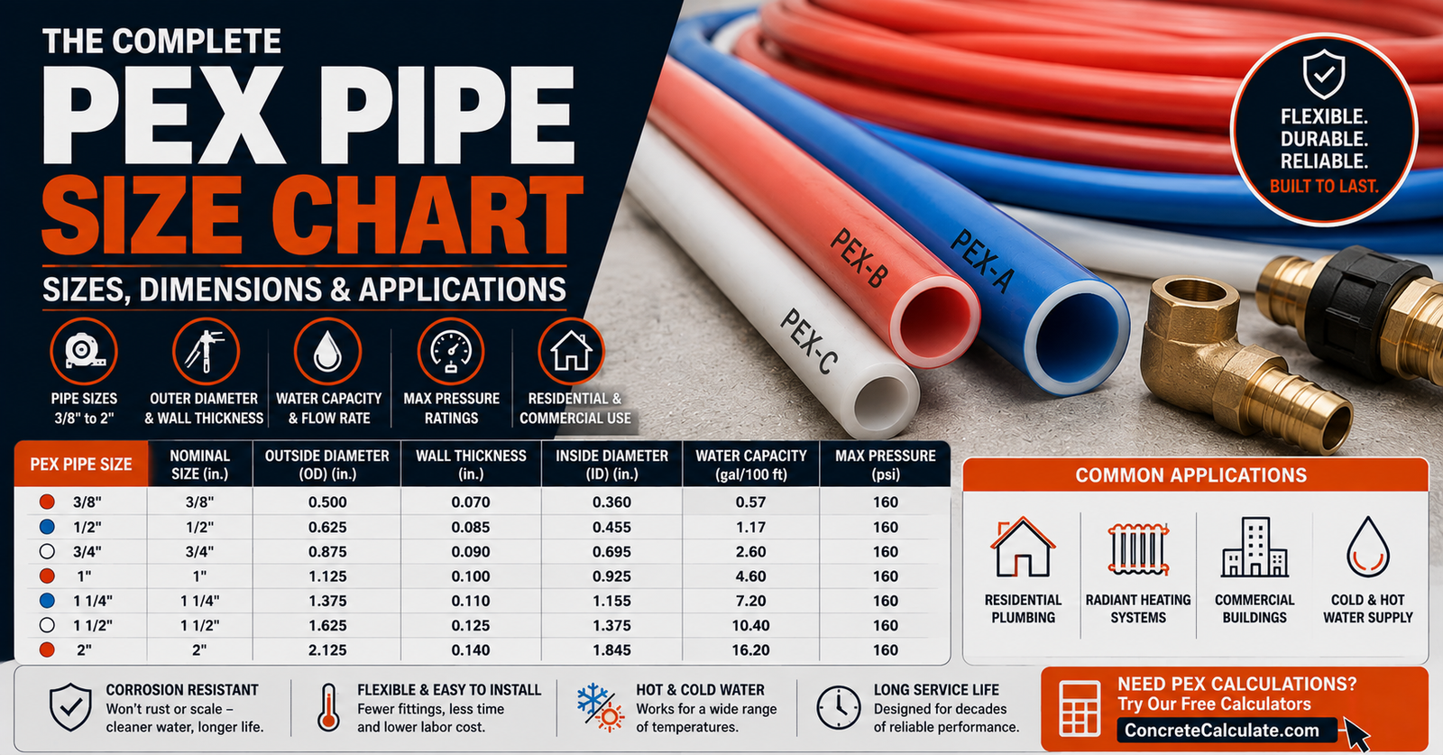
PEX tubing is sized by CTS convention, not by its actual outside diameter. This chart provides verified OD, ID, wall thickness and flow area by nominal size, based on ASTM F876, along with flow rate and pressure loss reference data.
 Reviewed by Muhammad Ramzan Babar, PhD Researcher & Calculator Developer · View Profile
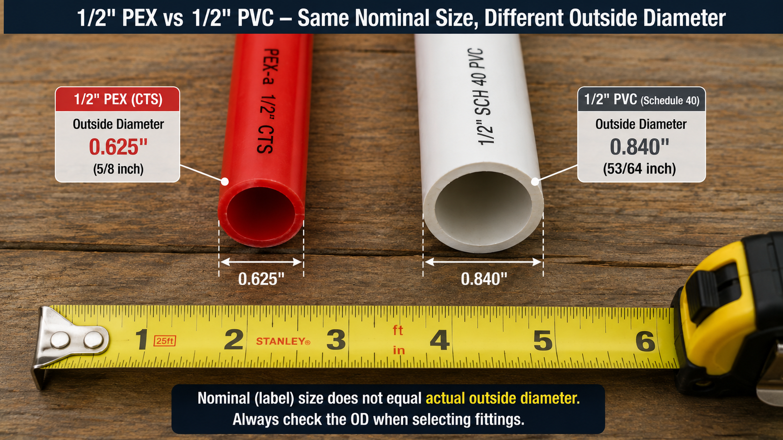
PEX tubing follows the CTS (Copper Tube Size) convention, not NPS pipe sizing. Nominal 1/2 inch PEX has an average outside diameter of approximately 0.625 inches under ASTM F876. This gap between the nominal label and the actual measurement is the most common source of confusion when comparing PEX to PVC pipe.
⭐⭐⭐⭐⭐ PEX Pipe Size Chart: Quick Reference
Nominal CTS size, actual outside diameter, minimum wall thickness, average inside diameter and flow area for common PEX tubing.
| Nominal Size (CTS) | Avg. OD (in) | Min. Wall (in) | Avg. ID (in) | Flow Area (in²) | Typical Application |
|---|---|---|---|---|---|
| 3/8″ | 0.500 | 0.070 | 0.360 | 0.102 | Fixture drops, manifold home runs |
| 1/2″ | 0.625 | 0.070 | 0.485 | 0.185 | Individual fixture branches, home runs |
| 5/8″ | 0.750 | 0.083 | 0.584 | 0.268 | Extended branch runs |
| 3/4″ | 0.875 | 0.097 | 0.681 | 0.364 | Main distribution, multi-fixture branches |
| 1″ | 1.125 | 0.125 | 0.875 | 0.601 | Building supply, main trunk lines |
| 1-1/4″ | 1.375 | 0.153 | 1.069 | 0.897 | Larger distribution mains |
| 1-1/2″ | 1.625 | 0.181 | 1.263 | 1.253 | Commercial/multi-unit distribution |
| 2″ | 2.125 | 0.236 | 1.653 | 2.146 | Larger commercial systems |
Dimensions follow ASTM F876, the governing specification for crosslinked polyethylene (PEX) tubing in the CTS SDR 9 series. Inside diameter and flow area vary somewhat by manufacturer and product line, so these figures should be treated as representative averages rather than a universal fixed value for every listed PEX product.
⭐⭐⭐⭐ What Is PEX Pipe?
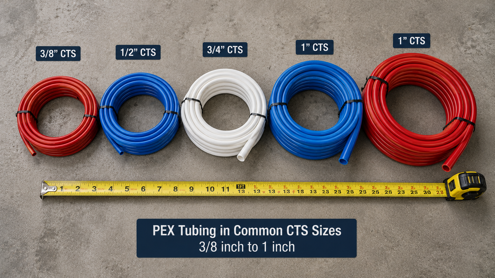
PEX stands for crosslinked polyethylene, a flexible thermoplastic tubing material widely used in residential and commercial plumbing.
Flexible tubing, not rigid pipe
PEX bends around obstacles and through framing without many of the fittings rigid pipe requires, reducing joints in a system.
Hot and cold water applications
PEX is used for both hot and cold water distribution, with pressure ratings that vary by temperature.
Residential and commercial use
Common in single-family homes, multifamily buildings, and some commercial plumbing systems for water distribution.
Three manufacturing types
PEX is produced as PEX-A, PEX-B or PEX-C, referring to the crosslinking method used, not a quality ranking.
⭐⭐⭐⭐⭐ What Does PEX Pipe Size Mean?
This is the single most important concept for anyone shopping for PEX tubing or fittings.
A 1/2 inch PEX tube does not have a 1/2 inch outside diameter. PEX uses a nominal, CTS-based sizing convention rather than a direct measurement. Under the common CTS SDR 9 system defined by ASTM F876, a 1/2 inch PEX tube has an average outside diameter of approximately 0.625 inches, not 0.500 inches.
Because nominal size and actual OD differ, PEX fittings, clamps and support spacing are all selected by nominal CTS size, not by directly measuring “1/2 inch” on a ruler. Confusing the two is the most common PEX identification error.
⭐⭐⭐⭐⭐ PEX CTS Sizing Explained
CTS stands for Copper Tube Size, the nominal sizing convention PEX tubing generally follows.
What CTS means
CTS sizing assigns a nominal label to a tube based on a historical copper tubing dimension series, where actual OD does not equal the nominal number.
Why PEX uses CTS
PEX was developed as a copper tube replacement in water distribution systems, so it adopted the same nominal sizing family to remain compatible with existing fitting and installation conventions.
Relationship to copper tubing
PEX and copper commonly share the same nominal size labels and similar outside diameters, though wall thickness and actual inside diameter differ by material and product.
CTS is not NPS
CTS sizing should never be confused with NPS (nominal pipe size) sizing used by PVC and steel pipe, since the same nominal number produces a different actual outside diameter under each system.
⭐⭐⭐⭐⭐ PEX Size Chart in Inches and Millimeters
Metric equivalents are converted dimensions for reference, not separate metric nominal sizes.
| Nominal Size | OD (in) | OD (mm) | Approx. ID (in) | Approx. ID (mm) |
|---|---|---|---|---|
| 3/8″ | 0.500 | 12.70 | 0.360 | 9.14 |
| 1/2″ | 0.625 | 15.88 | 0.485 | 12.32 |
| 5/8″ | 0.750 | 19.05 | 0.584 | 14.83 |
| 3/4″ | 0.875 | 22.23 | 0.681 | 17.30 |
| 1″ | 1.125 | 28.58 | 0.875 | 22.23 |
| 1-1/4″ | 1.375 | 34.93 | 1.069 | 27.15 |
| 1-1/2″ | 1.625 | 41.28 | 1.263 | 32.08 |
| 2″ | 2.125 | 53.98 | 1.653 | 41.99 |
⭐⭐⭐⭐⭐ PEX Outside Diameter Chart
A dedicated OD reference, useful for measuring existing tubing, selecting fittings and clamps, and drilling framing holes.
| Nominal Size | Average OD (in) |
|---|---|
| 3/8″ | 0.500 |
| 1/2″ | 0.625 |
| 5/8″ | 0.750 |
| 3/4″ | 0.875 |
| 1″ | 1.125 |
| 1-1/4″ | 1.375 |
| 1-1/2″ | 1.625 |
| 2″ | 2.125 |
These are average outside diameters under ASTM F876 tolerances. Actual measured OD on a specific product may vary slightly within the standard’s allowed tolerance band.
⭐⭐⭐⭐⭐ PEX Inside Diameter Chart
Inside diameter determines flow area and matters more for hydraulic performance than nominal size alone.
| Nominal Size | Min. Wall (in) | Avg. ID (in) |
|---|---|---|
| 3/8″ | 0.070 | 0.360 |
| 1/2″ | 0.070 | 0.485 |
| 5/8″ | 0.083 | 0.584 |
| 3/4″ | 0.097 | 0.681 |
| 1″ | 0.125 | 0.875 |
| 1-1/4″ | 0.153 | 1.069 |
| 1-1/2″ | 0.181 | 1.263 |
| 2″ | 0.236 | 1.653 |
Some references show average ID, others show a calculated ID derived from OD minus twice the minimum wall thickness. These are not always identical figures. Confirm which definition a source uses before mixing values from multiple charts into one calculation.
⭐⭐⭐⭐⭐ PEX Wall Thickness Chart
Wall thickness under ASTM F876 follows the SDR 9 ratio, meaning OD divided by wall thickness equals approximately 9.
| PEX Size | OD (in) | Min. Wall (in) | ID (in) | Nominal SDR |
|---|---|---|---|---|
| 3/8″ | 0.500 | 0.070 | 0.360 | 9 |
| 1/2″ | 0.625 | 0.070 | 0.485 | 9 |
| 5/8″ | 0.750 | 0.083 | 0.584 | 9 |
| 3/4″ | 0.875 | 0.097 | 0.681 | 9 |
| 1″ | 1.125 | 0.125 | 0.875 | 9 |
| 1-1/4″ | 1.375 | 0.153 | 1.069 | 9 |
| 1-1/2″ | 1.625 | 0.181 | 1.263 | 9 |
| 2″ | 2.125 | 0.236 | 1.653 | 9 |
Average vs minimum wall
ASTM F876 specifies a minimum wall thickness; actual manufactured wall thickness is typically at or slightly above that minimum, within stated tolerances.
Manufacturing tolerances
OD and wall thickness both carry allowed tolerance ranges, so two compliant products can measure slightly differently while both meeting ASTM F876.
⭐⭐⭐⭐⭐ What Is SDR 9 PEX?
SDR stands for Standard Dimension Ratio, the ratio of outside diameter to wall thickness.
SDR = Outside Diameter ÷ Wall Thickness. PEX tubing under ASTM F876 is dimensioned to an SDR of 9, meaning wall thickness scales proportionally with outside diameter across the size range, rather than following a stepped series like PVC Schedule pipe.
Because SDR is a ratio rather than a fixed value, wall thickness increases as nominal size increases, which is why larger PEX sizes show proportionally thicker walls in the chart above. SDR 9 is the dimensional basis for standard CTS PEX tubing, but it does not by itself establish a single universal pressure rating, since pressure rating also depends on the material’s hydrostatic design stress and the specific temperature condition.
Manufacturers may offer product lines with different tolerances or additional layers, such as oxygen-barrier or PEX-AL-PEX composite tubing, that can have different dimensional or performance characteristics than standard SDR 9 CTS PEX. Always confirm actual product specifications.
⭐⭐⭐⭐⭐ PEX-A vs PEX-B vs PEX-C Sizes
All three types commonly share the same nominal CTS sizing, but manufacturing method and fitting compatibility differ.
| Feature | PEX-A | PEX-B | PEX-C |
|---|---|---|---|
| Nominal sizing | CTS | CTS | CTS |
| Crosslinking method | Peroxide (Engel) method during extrusion | Silane moisture-cure method after extrusion | Electron beam irradiation after extrusion |
| Relative flexibility | Most flexible | Stiffer than PEX-A | Stiffest of the three |
| Expansion fitting compatibility | Commonly used, including ASTM F1960 expansion fittings | Product-dependent, generally not as widely rated for expansion connections | Product-dependent, generally not recommended by some manufacturers for expansion connections |
| Dimensional compatibility | Verify against product data | Verify against product data | Verify against product data |
PEX-A, PEX-B and PEX-C describe the manufacturing process used to crosslink the polyethylene, not a quality or performance grade. Fitting systems, installation methods and handling characteristics differ between types, but a given nominal size shares the same CTS sizing family across all three. Always confirm the specific fitting system a product is rated for before mixing tubing and fittings from different manufacturers.
⭐⭐⭐⭐⭐ PEX Size vs Fitting Size
Nominal tubing size, fitting bore, and flow capacity are three separate things.
Crimp fittings
Use a copper crimp ring compressed onto the tubing over an insert fitting, common with PEX-B and PEX-C systems.
Clamp fittings
Use a stainless steel clamp ring tightened with a specific tool, an alternative to crimp connections.
Expansion fittings
Use a cold-expansion tool to stretch the tubing over a fitting that then contracts to form the seal, most associated with PEX-A due to its elastic memory.
Press fittings
Use a press tool to mechanically compress a fitting sleeve onto the tubing, common in some commercial systems.
Push-fit fittings
Allow tool-free connection by pushing the tubing into a fitting with internal grab and sealing elements.
Fitting selection rule
Always match fitting type and nominal size to the specific tubing type and manufacturer, since bore dimensions inside fittings are not standardized identically across all fitting systems.
⭐⭐⭐⭐⭐ PEX Fitting Inside Diameter and Flow
Fittings can introduce additional pressure loss and may present a smaller effective flow passage than the tubing itself.
A 3/4 inch PEX system does not necessarily have identical hydraulic behavior at every connection point. Insert-style fittings, in particular, can reduce the effective bore compared to the tubing’s own inside diameter, and each fitting adds a measurable equivalent length of pressure loss to the overall run.
When calculating total system pressure loss, account for fitting losses separately from straight-run tubing losses, using the fitting manufacturer’s equivalent length or loss coefficient data rather than assuming the fitting behaves identically to an equal length of open tubing.
⭐⭐⭐⭐⭐ PEX Pipe Size by Application
PEX sizing decisions are organized by system role rather than a single size-per-room approach.
Individual fixture supply
Home-run drops from a manifold to a single fixture, commonly 3/8 or 1/2 inch depending on fixture demand and run length.
Bathroom groups & kitchen
Branches serving multiple fixtures in one area, sized for combined simultaneous demand rather than a single fixture’s requirement.
Laundry
Washing machine connections have their own flow demand and often benefit from dedicated sizing consideration on longer runs.
Branch lines & main distribution
Branch lines feed groups of fixtures; main distribution lines carry the combined demand from all downstream branches.
Manifold systems
Central manifolds distribute water to individual home-run branches, with manifold body sizing based on total connected demand.
Building supply & water service
The line entering the building from the meter or well, generally sized to the largest diameter in a residential system per applicable code minimums.
⭐⭐⭐⭐⭐ PEX Size for Individual Fixtures
Fixture demand and local code requirements determine sizing, not a fixed universal rule per fixture type.
| Fixture | Sizing Consideration |
|---|---|
| Bathroom sink | Low individual flow demand; run length and simultaneous use still matter |
| Kitchen sink | Moderate demand; consider dishwasher branch if shared |
| Toilet | Low flow demand per IRC fixture unit tables; short connections sometimes permitted at reduced size |
| Shower | Higher flow demand; sizing depends on showerhead flow rate and available pressure |
| Bathtub | Fixture unit value differs from a shower; check applicable code table |
| Washing machine | Higher simultaneous flow demand, often a dedicated valve connection |
| Dishwasher | Typically supplied from the kitchen hot branch; confirm manufacturer connection requirements |
| Hose bibb | Outdoor demand and freeze-protection requirements affect sizing and installation |
Fixture unit values used for sizing calculations come from the applicable plumbing code’s fixture unit table, such as IRC Table P2903.6, not from a generic industry rule of thumb.
⭐⭐⭐⭐⭐ PEX Size for Shower Lines
Shower sizing is a system-level decision, not a fixed nominal size.
Do not assume that 1/2 inch PEX is automatically correct for every shower. The right size depends on several factors together: the showerhead’s actual flow demand, available static pressure at the fixture, whether other fixtures draw water simultaneously, total run length from the source or manifold, the number and type of fittings in the run, and whether the system includes a thermostatic or pressure-balancing valve that has its own flow requirements.
Short, dedicated run
A short home-run branch to a single shower with typical residential pressure often performs adequately at 1/2 inch.
Long run or shared branch
A long run, a branch shared with other fixtures, or a high-flow showerhead can justify upsizing to 3/4 inch to control pressure loss.
⭐⭐⭐⭐ PEX Size for Kitchen and Bathroom Branches
Branch sizing depends on combined demand from every fixture the branch serves.
Branch demand
Total the fixture unit demand of every fixture connected downstream of a branch point before selecting its size.
Simultaneous use
Consider realistic simultaneous use patterns, such as a shower and a bathroom sink both running at once.
Hot vs cold supply
Hot and cold branches can carry different demand profiles and are sized independently based on their own fixture connections.
Run length & pressure loss
Longer branch runs lose more pressure at a given flow rate, which can justify upsizing even when fixture unit totals alone might suggest a smaller pipe.
⭐⭐⭐⭐⭐ PEX Size for Main Water Lines
Main line sizing follows a demand-based methodology rather than a size chosen by building area.
Under IRC 2024 Section P2903.1, water piping sizing considers total fixture unit demand, available water pressure, developed length and fitting losses together, rather than assigning a single nominal size based on square footage or fixture count alone. IRC 2024 commonly requires at least a 3/4 inch building supply, with branch lines to individual fixtures typically sized to at least 1/2 inch, subject to the fixture unit and pressure calculation.
Main distribution lines carry the combined demand of every downstream branch and fixture, so main sizing should reflect that cumulative fixture unit load rather than matching the size of any single branch it feeds.
⭐⭐⭐⭐⭐ PEX Size for Manifold Systems
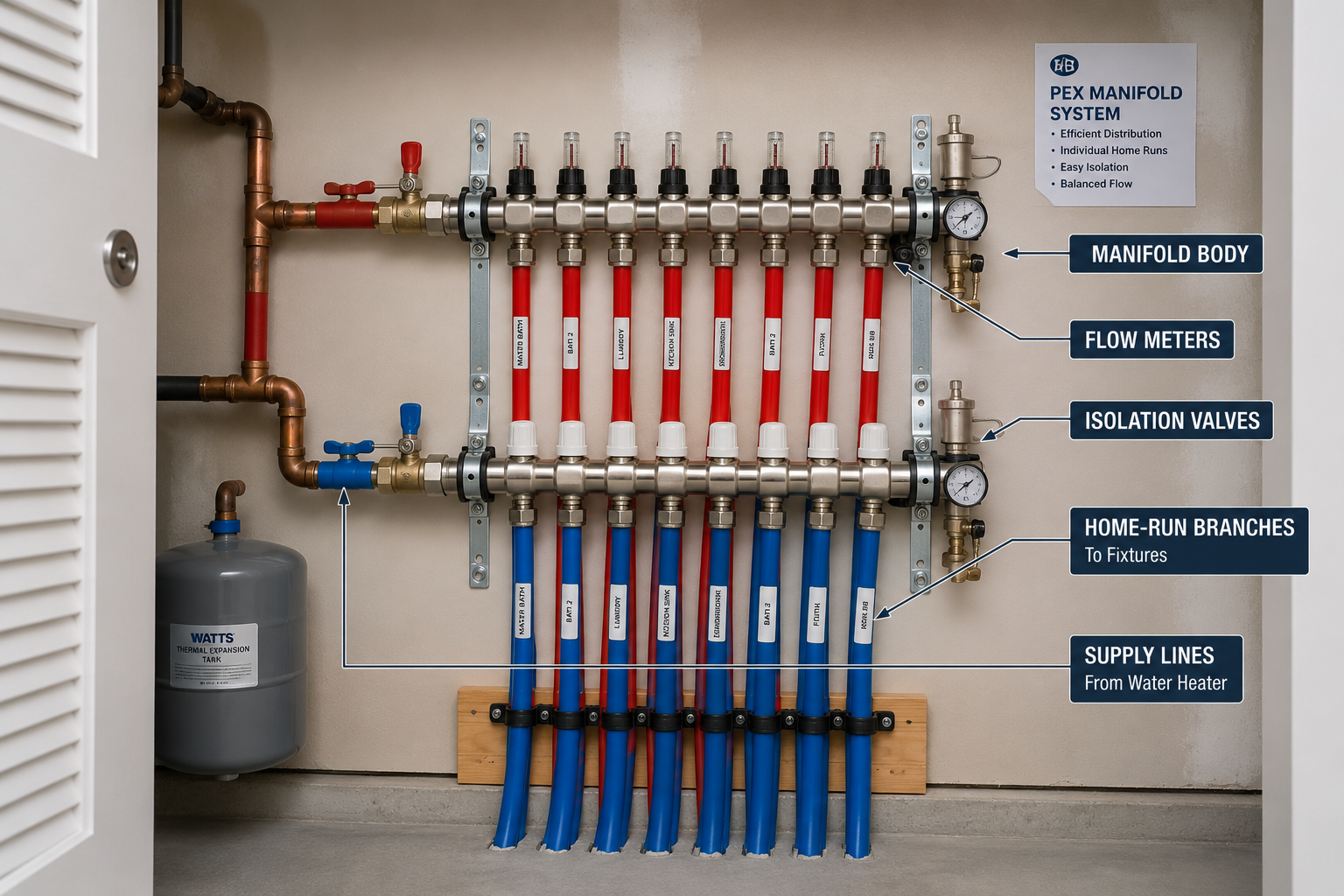
Manifold, or home-run, distribution routes an individual PEX line from a central manifold to each fixture.
Central manifold
A manifold body distributes water from the main supply to multiple individual branch ports.
Hot and cold manifolds
Systems commonly use separate hot and cold manifolds, each sized for its own connected fixture demand.
Individual fixture branches
Each home-run branch from the manifold to a fixture is sized individually, commonly 3/8 or 1/2 inch depending on the fixture and run length.
Parallel distribution benefit
Because each fixture has its own dedicated line, manifold systems can reduce pressure competition between fixtures compared to trunk-and-branch layouts, though every run still needs correct individual sizing.
⭐⭐⭐⭐ PEX Manifold Size vs Branch Line Size
Manifold body sizing and individual branch sizing are two separate decisions.
A manifold inlet undersized relative to the total fixture unit load of all its connected branches can become the limiting point in the system, producing a pressure drop that affects every fixture simultaneously regardless of how well each individual branch was sized.
Size the manifold inlet and body for the combined demand of all branches it serves, then size each individual branch separately according to that specific fixture’s demand and run length.
⭐⭐⭐⭐⭐ PEX Flow Rate by Pipe Size
Flow rate depends on pipe size together with velocity, pressure and tubing dimensions; it is not a fixed property of nominal size alone.
| PEX Size | Approx. ID (in) | Minimum Flow Rate (GPM) | Maximum Flow Rate (GPM) |
|---|---|---|---|
| 3/8″ | 0.360 | 0.6 | 1.3 |
| 1/2″ | 0.485 | 1.2 | 2.3 |
| 5/8″ | 0.584 | 1.7 | 3.3 |
| 3/4″ | 0.681 | 2.3 | 4.6 |
| 1″ | 0.875 | 3.8 | 7.5 |
| 1-1/4″ | 1.069 | 5.6 | 11.2 |
| 1-1/2″ | 1.263 | 7.8 | 15.6 |
| 2″ | 1.653 | 13.4 | 26.8 |
These minimum and maximum flow rate figures come from published manufacturer flow-rate reference data for PEX tubing and correspond to that source’s assumed velocity range. Different manufacturers or design guides may publish somewhat different flow figures for the same nominal size depending on the velocity limits and tubing dimensions they assume.
⭐⭐⭐⭐⭐ PEX GPM Chart
A direct size-to-GPM reference, not a universal capacity guarantee for every product and installation.
The flow rate table above already expresses a minimum-to-maximum GPM range for each PEX size based on published manufacturer flow-rate data. The minimum figure generally reflects a lower, quieter velocity, while the maximum figure approaches a higher velocity limit that some codes and design guides discourage exceeding on a sustained basis due to noise, erosion and pressure loss concerns. Use the lower portion of the range for quiet, long-term operation and the upper portion only when confirmed appropriate by the applicable code and manufacturer guidance.
⭐⭐⭐⭐ PEX Flow Velocity Chart
Velocity affects noise, pressure loss and long-term system performance.
Why velocity matters
Higher velocity increases friction loss and noise, and can accelerate wear at fittings and direction changes over the system’s service life.
Typical code guidance
Some residential plumbing codes reference maximum velocity limits, commonly cited around 8 feet per second for cold water and a lower limit for hot water, though the applicable limit depends on the specific code adopted and the piping material.
Not a universal design rule
Maximum velocity guidance varies by code edition, jurisdiction and material. Confirm the applicable limit rather than applying one number to every project.
Erosion and fixture performance
Excessive velocity at fittings can contribute to noise and, in some materials, erosion-related wear, while insufficient velocity in oversized pipe can slow hot water delivery.
Equipment for Your Project
Affiliate disclosure: As an Amazon Associate, ConcreteCalculate earns from qualifying purchases. We may also earn a commission from other affiliate links at no additional cost to you.
⭐⭐⭐⭐⭐ PEX Pressure Loss Chart
Pressure loss depends on pipe size, flow rate, length and the fittings in the run.
Total system pressure loss combines friction loss through straight tubing runs, additional loss through each fitting expressed as an equivalent length, and any elevation change in the piping route. Larger diameter tubing reduces friction loss at a given flow rate, while longer runs and more fittings increase total loss.
Because pressure loss depends on the specific flow rate, exact run length, fitting count and product dimensions of a given installation, a single universal pressure-loss number cannot be assigned to a nominal PEX size without those project-specific inputs. Manufacturer friction-loss tables and design software use the tubing’s actual inside diameter together with the Hazen-Williams or Darcy-Weisbach method to calculate loss for a specific flow rate and length.
⭐⭐⭐⭐⭐ PEX Friction Loss Chart
Friction loss increases with flow rate and pipe length, and decreases as pipe diameter increases.
Flow rate
Higher flow rate through the same pipe size increases friction loss per unit length.
Equivalent length
Fittings, valves and direction changes are converted to an equivalent length of straight pipe for friction-loss calculation purposes.
Pipe size
A larger inside diameter reduces friction loss at the same flow rate, which is why upsizing is a common remedy for excessive pressure drop.
Manufacturer-specific data required
Precise friction-loss figures depend on the tubing’s actual inside diameter and roughness, so refer to the specific manufacturer’s published friction-loss table for design calculations rather than a generic industry-wide number.
⭐⭐⭐⭐⭐ PEX Pipe Size vs Pressure Loss
The underlying engineering relationship behind PEX sizing decisions.
Larger diameter tubing generally produces lower friction loss at the same flow rate, because the same volume of water moves at a lower velocity through a larger cross-sectional area. Conversely, a longer pipe run, additional fittings, or elevation gain all increase total pressure loss regardless of pipe size. This is why a short 1/2 inch branch can perform well while a long 1/2 inch run serving multiple fixtures may not, even though both use the same nominal pipe size.
⭐⭐⭐⭐⭐ PEX Pipe Size and Water Pressure
Delivered pressure at a fixture results from several factors acting together.
| Factor | Effect on Delivered Pressure |
|---|---|
| Source/static pressure | Sets the starting pressure available to the system |
| Elevation change | Vertical rise reduces pressure; vertical drop can increase it |
| Pipe friction loss | Increases with flow rate and length, decreases with larger diameter |
| Fitting losses | Each fitting adds a small additional pressure loss |
| Fixture pressure requirement | Each fixture needs a minimum flowing pressure to perform as intended |
| Simultaneous flow demand | Multiple fixtures drawing at once increases total flow and total loss |
The IRC 2024 water-piping sizing methodology explicitly considers available pressure and friction losses, together with fixture demand and developed length, when determining minimum water-piping size, rather than relying on nominal pipe size alone.
⭐⭐⭐⭐⭐ How to Choose the Right PEX Size
A practical sizing workflow rather than picking a size from habit.
Determine what the pipe run needs to supply, from a single fixture to a full building main.
Establish the flow demand in gallons per minute for the fixture or combined fixtures served.
Check static pressure at the source and account for expected pressure at the point of use.
Measure the actual routed length of the pipe run, including vertical sections.
Add or subtract pressure effects from vertical rise or drop along the route.
Convert fittings and valves to an equivalent length for pressure-loss calculation.
Use the applicable plumbing code’s fixture unit table to total demand on shared branches and mains.
Choose the smallest size that satisfies flow, pressure and velocity requirements for the calculated demand and length.
Confirm the selected product’s actual dimensions and pressure rating support the design.
Verify the final selection satisfies the adopted code edition and any local amendments.
⭐⭐⭐⭐⭐ PEX Size by Water Supply Fixture Units
WSFU is the standardized demand unit used in code-based water-piping sizing.
Water Supply Fixture Units (WSFU) assign a standardized demand value to each fixture type, reflecting its typical flow contribution to peak system demand. The applicable plumbing code, such as the IRC, lists WSFU values for common fixtures in a dedicated table. A designer totals the WSFU for all fixtures on a branch or main, then cross-references that total against the available static pressure and developed length using the code’s sizing tables to determine minimum pipe diameter.
A statement such as “four fixtures require 1/2 inch PEX” is too simplistic. The correct minimum size depends on which fixtures are involved, their individual WSFU values, the total combined demand, available pressure, and developed length, evaluated together through the applicable code’s sizing method.
⭐⭐⭐⭐⭐ PEX Pipe Size and Developed Length
Developed length is the actual piping route length, adjusted for the effect of fittings under the applicable sizing method.
Long runs
Longer developed length increases total friction loss at a given flow rate, which can require upsizing to maintain adequate delivered pressure.
Branches and remote fixtures
A fixture far from the source or manifold experiences more accumulated pressure loss than one close to it, even at the same nominal pipe size.
Fittings within developed length
Many sizing methods add an equivalent length for fittings to the physical pipe length, since each fitting contributes measurable additional loss.
Code-based calculation
The IRC 2024 sizing methodology specifically incorporates developed length and equivalent fitting losses into its water-piping sizing tables and calculations.
⭐⭐⭐⭐ PEX Pipe Size for Long Runs
A short branch and a long run serving multiple fixtures are not equivalent, even at the same nominal size.
Pressure loss accumulates with length
Every additional foot of developed length adds friction loss, which can push delivered pressure below an acceptable level on long runs.
Upsizing as a remedy
Increasing pipe size on a long run reduces velocity and friction loss for the same flow rate, helping maintain adequate pressure at the far end.
Fixture demand still matters
A long run serving only one low-demand fixture may perform fine at a smaller size, while a long run serving several fixtures may need upsizing regardless of length alone.
Manifold layouts as an alternative
Home-run manifold systems can shorten individual branch lengths compared to a long trunk-and-branch run, changing the sizing calculation for each fixture.
⭐⭐⭐⭐⭐ PEX vs Copper Size Comparison
Both materials commonly use CTS sizing, but internal dimensions and installation differ by product.
| Feature | PEX | Copper (Type L, typical) |
|---|---|---|
| Nominal sizing convention | CTS | CTS |
| 1/2 inch nominal OD | Approx. 0.625 in (ASTM F876) | Approx. 0.625 in (nominal copper tube OD family) |
| Wall/ID construction | Single-wall polymer tubing per SDR 9 | Rigid metal tubing with type-specific wall thickness (Type K/L/M) |
| Flexibility | Flexible, bends around obstacles | Rigid, requires fittings at direction changes |
| Common fittings | Crimp, clamp, expansion, press, push-fit | Soldered, brazed, press, flare |
| Installation | Fewer fittings on curved runs; freeze flexibility | More fittings required; less freeze tolerance |
PEX and copper sharing the CTS nominal sizing concept means their nominal size labels and general OD are comparable, but they remain different materials with different wall construction, pressure behavior and installation methods. See the Copper Pipe Size Chart for verified copper tube dimensions by type.
⭐⭐⭐⭐⭐ PEX vs CPVC vs PVC Size Comparison
These materials do not all use the same sizing convention, and this is one of the most common points of confusion in plumbing.
| Nominal Size | PEX (CTS, OD in) | PVC Sch 40 (NPS, OD in) |
|---|---|---|
| 1/2″ | 0.625 | 0.840 |
| 3/4″ | 0.875 | 1.050 |
| 1″ | 1.125 | 1.315 |
PEX generally follows CTS sizing, where 1/2 inch nominal has an outside diameter of about 0.625 inches. PVC under ASTM D1785 follows NPS/IPS sizing, where 1/2 inch nominal has an outside diameter of about 0.840 inches. CPVC tubing sized to CTS convention, where offered, follows the copper tube size family similar to PEX rather than the PVC NPS series. Always confirm which sizing convention a specific CPVC product uses before assuming compatibility. See the PVC Pipe Size Chart for full Schedule 40/80/120 and SDR dimensions.
⭐⭐⭐⭐⭐ PEX Nominal Size vs Actual Size
Reinforcing the central sizing concept with verified standard values.
| Nominal Size | Actual OD (in) |
|---|---|
| 3/8″ | 0.500 |
| 1/2″ | 0.625 |
| 5/8″ | 0.750 |
| 3/4″ | 0.875 |
| 1″ | 1.125 |
| 1-1/4″ | 1.375 |
| 1-1/2″ | 1.625 |
| 2″ | 2.125 |
⭐⭐⭐⭐⭐ How to Identify PEX Pipe Size
Printed tubing markings are the fastest reliable identification method when legible.
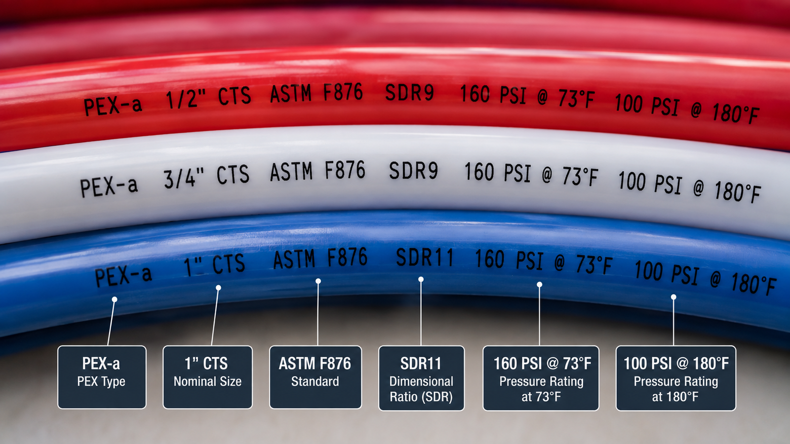
| Marking Element | Example | Meaning |
|---|---|---|
| Nominal size | 1/2 IN CTS | Standardized CTS nominal designation |
| ASTM standard | ASTM F876 | Governing tubing dimensional and performance specification |
| System standard | ASTM F877 | Governing hot and cold water distribution system specification |
| SDR | SDR 9 | Standard dimension ratio identifying the OD-to-wall relationship |
| Pressure/temperature rating | 160 PSI @ 73.4F / 100 PSI @ 180F | Product-specific pressure rating at stated reference temperatures |
| Manufacturer | Company name/logo | Identifies the producer for warranty and specification lookup |
| Listing marks | NSF-pw | Certification for potable water use, where applicable |
⭐⭐⭐⭐⭐ How to Measure PEX Pipe Size
The full workflow for identifying an unmarked or unreadable PEX tube.
Check for nominal size, ASTM standard, SDR and pressure rating text along the tubing.
Use a caliper or tape measure at the widest point of the tube.
Match the reading against the standard nominal size table above.
A similar OD measurement does not confirm PEX type, pressure rating or governing standard by itself.
Contact the manufacturer or check accompanying documentation to confirm the exact product specification.
⭐⭐⭐⭐⭐ PEX Pressure and Temperature Ratings
Ratings are product-specific and must be verified from the actual tubing, not assumed universal.
| Reference Condition | Commonly Published Rating |
|---|---|
| 73.4°F | 160 psi |
| 180°F | 100 psi |
Industry design guidance and manufacturer technical data commonly publish a 160 psi rating at 73.4 degrees Fahrenheit and a 100 psi rating at 180 degrees Fahrenheit for standard PEX tubing, but the actual pressure rating belongs to the specific listed product and must be confirmed from that product’s printed markings or manufacturer documentation, especially for specialty or composite tubing products.
⭐⭐⭐⭐ PEX-A, PEX-B and PEX-C Pressure/Temperature Considerations
Rating information should always come from the product marking, not from assumptions about PEX type.
Pressure and temperature ratings for a given PEX product should be taken from its printed marking, manufacturer technical data, and applicable listing or standard. Do not assume that one PEX type is universally “strongest” or “weakest,” since crosslinking method primarily affects flexibility and fitting compatibility rather than establishing a fixed, industry-wide pressure hierarchy across every manufacturer’s product line.
⭐⭐⭐⭐⭐ PEX Standards and Plumbing Codes
Multiple standards and code references govern PEX tubing, systems and applications.
| Standard/Code | Covers |
|---|---|
| ASTM F876 | Specification for Crosslinked Polyethylene (PEX) Tubing, including CTS SDR 9 dimensions |
| ASTM F877 | Specification for Crosslinked Polyethylene (PEX) Plastic Hot and Cold Water Distribution Systems |
| AWWA C904 | Relevant to PEX water-service line applications where applicable |
| CSA B137.5 | Canadian standard for crosslinked polyethylene systems for pressure applications |
| NSF/ANSI 61 | Relevant to drinking-water system component health effects |
| IRC / IPC | Relevant to residential and general plumbing design and water-piping sizing requirements |
The 2024 International Residential Code references ASTM F876 and F877 for PEX tubing and system applications, and requires water-piping sizing based on fixture demand, available pressure and developed length rather than nominal size alone.
⭐⭐⭐⭐⭐ PEX Pipe Size Chart Limitations
Understanding what this chart does not tell you is as important as the dimensional data itself.
Nominal size alone does not establish flow capacity
Actual hydraulic performance depends on ID, pressure, length and fittings together.
ID varies with product dimensions
Different manufacturers can show slightly different average or calculated ID for the same nominal size.
Fittings affect pressure loss
Each fitting adds measurable equivalent length loss beyond the straight tubing run.
Pipe length and elevation matter
Longer runs and elevation changes both affect delivered pressure independent of pipe size.
Fixture demand matters
Total fixture unit load on a branch or main changes the correct sizing outcome.
Local code and manufacturer instructions govern the final decision
Always confirm sizing against the applicable adopted code and the specific product’s installation instructions.
Temperature affects pressure rating
A product’s pressure rating decreases as operating temperature increases, per its listed ratings.
PEX type does not determine nominal size
PEX-A, PEX-B and PEX-C share the same CTS sizing family; type affects handling and fittings, not the nominal size chart itself.
⭐⭐⭐⭐⭐ PEX Pipe Size Worked Examples
These examples demonstrate the sizing and identification process using stated assumptions, not a code-compliance determination.
1. Choosing PEX for a single bathroom fixture
2. Sizing a branch serving multiple fixtures
3. Choosing PEX for a long run
4. Comparing 1/2 inch and 3/4 inch PEX
5. Identifying existing PEX from its OD
⭐⭐⭐⭐⭐ Common PEX Sizing Mistakes
Most PEX sizing errors trace back to one of these misunderstandings.
❌ Confusing nominal size with OD
Nominal CTS size and actual outside diameter are different values for PEX.
❌ Treating PEX like PVC sizing
PEX uses CTS sizing while PVC commonly uses NPS/IPS sizing, producing different OD at the same nominal label.
❌ Choosing pipe based only on fixture connection size
Fixture supply valve size does not by itself determine correct branch tubing size.
❌ Ignoring pressure loss
Longer runs and more fittings increase pressure loss regardless of nominal size.
❌ Ignoring developed length
A short and a long run at the same nominal size do not perform identically.
❌ Ignoring simultaneous demand
Multiple fixtures drawing at once increase total flow requirements on shared branches and mains.
❌ Ignoring fittings
Fittings add equivalent length and can reduce effective flow passage compared to the tubing itself.
❌ Assuming 1/2 inch PEX always supplies one fixture only
Sizing depends on actual demand and length, not a fixed assumption about fixture count.
❌ Assuming 3/4 inch PEX always solves low pressure
Low pressure can originate from the source, a pressure-reducing valve, or restrictions elsewhere in the system, not only pipe size.
❌ Confusing PEX-A/B/C with different nominal dimensions
All three commonly share the same CTS nominal sizing; the letters describe manufacturing method, not size.
❌ Ignoring product markings
Printed markings are the most reliable way to confirm standard, SDR and pressure rating.
❌ Using a generic pressure rating for every product
Pressure and temperature ratings are product-specific and must be verified from that product’s documentation.
Frequently Asked Questions
📄 Download PEX Pipe Size Chart PDF
This PDF is a genuine field reference. Use the print button to create a print-ready or downloadable version.
Cite or Embed This Chart
Copy the page-wide citation to reference the complete PEX Pipe Size Chart.