Pipe Pressure Rating Chart – PVC, CPVC, Steel & Flange Class
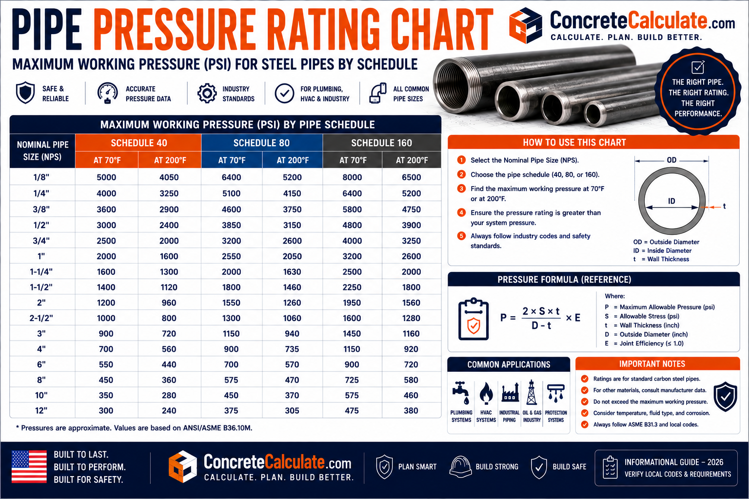
Pipe Pressure Rating Chart
PVC, CPVC, Steel & Flange Class
Pipe schedule does not by itself determine pressure rating. This chart provides genuine published pressure data where it exists and explains the engineering factors where it does not.
 Reviewed by Muhammad Ramzan Babar, PhD Researcher & Calculator Developer · View Profile
For metallic pipe, pressure capability must be calculated from the applicable design code (such as ASME B31.1 or B31.3), material properties, temperature, joint efficiency, and corrosion allowance. Only specific plastic pipe products with a governing pressure-rated standard, such as PVC under ASTM D1785, have standardized published pressure ratings by schedule and size, and even those change significantly with temperature.
⭐⭐⭐ Pipe Pressure Rating: Quick Reference
Notice that only plastic pipe rows show a rating value here. Steel rows correctly point to a design basis instead of a fabricated number.
| Material | Size | Schedule | Pressure Rating (73°F) | Standard |
|---|---|---|---|---|
| Steel | 1/2″ | Sch 40 | See design basis (ASME B31.1/B31.3) | ASME B36.10 + applicable code |
| Steel | 1/2″ | Sch 80 | See design basis (ASME B31.1/B31.3) | ASME B36.10 + applicable code |
| PVC | 1/2″ | Sch 40 | 358 psi | ASTM D1785 |
| PVC | 1/2″ | Sch 80 | 509 psi | ASTM D1785 |
| CPVC | 1/2″ | Sch 40 | 600 psi | ASTM F441 |
| CPVC | 1/2″ | Sch 80 | 850 psi (unthreaded) | ASTM F441 |
ASME B31.1 covers power piping design, materials, fabrication, and testing; ASME B31.3 covers process piping and pressure design. Both organize allowable pressure around design conditions, material allowable stress, and component-specific calculation, not a schedule lookup table. Publishing a fabricated PSI number for “steel Schedule 40” would be technically invalid.
⭐⭐⭐ What Is Pipe Pressure Rating?
Several related but distinct pressure terms must be kept separate.
| Term | Meaning |
|---|---|
| Working pressure | The pressure a system is intended to operate at during normal service |
| Design pressure | The pressure value used as the basis for engineering design calculations |
| Maximum allowable working pressure | A code, material, and design-dependent upper limit for safe continued operation |
| Test pressure | A pressure applied temporarily to verify integrity, typically higher than working pressure |
| Burst pressure | The pressure at which a component fails structurally; never an acceptable operating condition |
| Pressure-temperature rating | An allowable pressure value that is explicitly tied to a specific temperature, since the two are not independent |
A pipe or fitting may withstand pressure considerably above its rated working pressure during qualification or destructive testing, but that higher value is never an acceptable operating condition. ASTM D1785 separately addresses sustained pressure, burst pressure, and pressure rating requirements for PVC pipe as distinct concepts.
⭐⭐⭐ Pipe Pressure Rating Factors
Pressure capability is the result of many factors working together, not any single dimension.
Geometric factors
- Pipe material
- Outside diameter
- Wall thickness
- Schedule or SDR
Service conditions
- Operating temperature
- Design temperature
- Internal pressure
- Fluid type
Design and manufacturing factors
- Corrosion allowance
- Manufacturing tolerance
- Joint efficiency
- Weld quality
System factors
- Fittings, valves, flanges
- Supports
- Applicable design code
⭐⭐⭐ Does Pipe Schedule Determine Pressure Rating?
No, not by itself.
Schedule identifies a standardized wall thickness series. Pressure capability is an engineering design result that also depends on material, temperature, and the applicable code. Increasing wall thickness generally increases pressure capacity for a given geometry and material, but the actual allowable pressure still requires the complete design calculation, not a schedule-to-PSI lookup.
| Schedule | Relative Wall Thickness | Relative Pressure Capability Tendency |
|---|---|---|
| Schedule 10 | Thinner | Generally lower, subject to full design calculation |
| Schedule 40 | Moderate | Generally moderate, subject to full design calculation |
| Schedule 80 | Thicker | Generally higher, subject to full design calculation |
| Schedule 160 | Thickest common schedule | Generally highest among these, subject to full design calculation |
See the Pipe Wall Thickness Chart for actual wall dimensions by schedule and NPS.
⭐⭐⭐ Steel Pipe Pressure Design
Metallic pipe pressure design is fundamentally an engineering calculation, not a lookup table.
ASME B31.1: Power Piping
Covers design, materials, fabrication, erection, testing, examination, inspection, operation, and maintenance of power piping systems. Its design approach separates pressure design of straight pipe, pressure design of components, and guarding against pipe collapse.
ASME B31.3: Process Piping
Covers materials and components, design, fabrication, assembly, erection, examination, inspection, and testing of process piping. Pressure design is organized around design conditions (design pressure and design temperature), then pressure design of straight pipe and other components.
| Design Input | Role |
|---|---|
| Material grade | Determines allowable stress at the design temperature |
| NPS and OD | Establishes the geometry used in the pressure design equation |
| Wall thickness | One geometric input into the design calculation |
| Design temperature | Affects allowable stress; higher temperature generally reduces allowable stress |
| Joint/weld efficiency | Accounts for reduced strength at welded or other joints |
| Corrosion allowance | Added thickness beyond structural minimum to accommodate expected material loss |
The same nominal size and schedule can have very different allowable pressure depending on material grade, design temperature, and the applicable code’s specific requirements. Never present a single fixed PSI number as a substitute for the actual design calculation.
⭐⭐⭐ PVC Pipe Pressure Rating (ASTM D1785)
ASTM D1785 covers PVC Schedule 40, 80, and 120 pipe and includes sustained pressure, burst pressure, and pressure rating requirements. Unlike steel, PVC has genuine published pressure ratings by size.
| NPS | Sch 40 Max. Operating Pressure (73°F) | Sch 80 Max. Operating Pressure (73°F) |
|---|---|---|
| 1/2 | 358 psi | 509 psi |
| 3/4 | 289 psi | 413 psi |
| 1 | 270 psi | 378 psi |
| 1-1/4 | 221 psi | 312 psi |
| 1-1/2 | 198 psi | 282 psi |
| 2 | 166 psi | 243 psi |
| 2-1/2 | 182 psi | 255 psi |
| 3 | 158 psi | 225 psi |
| 4 | 133 psi | 194 psi |
| 6 | 106 psi | 167 psi |
| 8 | 93 psi | 148 psi |
| 10 | 84 psi | 140 psi |
| 12 | 79 psi | 137 psi |
PVC pressure ratings are established with a substantial safety margin below required minimum burst pressure. For example, 1/2 inch Schedule 40 PVC has a required minimum burst pressure of about 1,910 psi against a maximum operating pressure of about 358 psi, illustrating the margin between operating and burst conditions.
Ratings shown apply to water, non-shock service, at 73°F. Values decrease significantly at higher temperatures; see the temperature derating section below. Schedule 120 sizes and ratings exist under ASTM D1785 but are less commonly stocked than Schedule 40/80.
⭐⭐⭐ CPVC Pipe Pressure Rating (ASTM F441)
ASTM F441/F441M covers CPVC Schedule 40 and 80 pipe with its own pressure rating and testing requirements, kept separate from PVC values.
| NPS | Sch 40 Max. Design Pressure (73°F) | Sch 80 Unthreaded (73°F) | Sch 80 Threaded (73°F) |
|---|---|---|---|
| 1/2 | 600 psi | 850 psi | 420 psi |
| 3/4 | 480 psi | 690 psi | 340 psi |
| 1 | 450 psi | 630 psi | 320 psi |
| 1-1/4 | 370 psi | 520 psi | 260 psi |
| 1-1/2 | 330 psi | 470 psi | 240 psi |
| 2 | 280 psi | 400 psi | 200 psi |
| 2-1/2 | 300 psi | 420 psi | 210 psi |
| 3 | 260 psi | 370 psi | 190 psi |
| 4 | 220 psi | 320 psi | 160 psi |
| 6 | 180 psi | 280 psi | 140 psi |
| 8 | 160 psi | 250 psi | 120 psi |
Notice that threaded Schedule 80 CPVC has roughly half the pressure rating of unthreaded Schedule 80 at the same size, since cutting threads removes wall material and creates stress concentration. This is a critical distinction often missed when specifying threaded plastic pipe connections.
⭐⭐⭐ PVC vs CPVC Pressure Rating
CPVC is not simply “PVC with a higher pressure rating.” It is a chemically distinct material with its own governing standard.
| Feature | PVC | CPVC |
|---|---|---|
| Governing standard | ASTM D1785 | ASTM F441/F441M |
| Temperature capability | Generally suitable to about 140°F depending on application | Extended service temperature, commonly cited to about 180 to 200°F |
| 1/2 in Sch 40 pressure rating (73°F) | 358 psi | 600 psi |
| 1/2 in Sch 80 pressure rating (73°F) | 509 psi | 850 psi (unthreaded) |
CPVC’s chemical composition, with an added chlorine atom compared to PVC, extends its usable temperature range and can support different pressure ratings under its own ASTM F441 testing basis. Do not assume the two materials are interchangeable or that CPVC is simply an upgraded PVC; always use the correct material-specific standard.
⭐⭐⭐ SDR vs Schedule
SDR (Standard Dimension Ratio) is a different dimensioning approach common in pressure-rated plastic pipe.
SDR = Outside Diameter / Wall Thickness. A lower SDR number means a proportionally thicker wall relative to diameter, and generally a higher pressure rating for a given material and pressure class.
| Feature | Schedule | SDR |
|---|---|---|
| Common use | Steel and some plastic pipe | Pressure-rated plastic pipe (HDPE, some PVC products) |
| Basis | Standardized wall thickness series by NPS | Ratio of OD to wall thickness |
| Pressure rating | Depends on material and design basis, not schedule alone | Depends on material and pressure class, not SDR alone |
| Universal PSI value? | No | No |
⭐ HDPE, Copper & Ductile Iron Pressure Rating
Each of these materials uses its own dimensioning and pressure classification system.
HDPE pipe
Sized by SDR and pressure class (such as PE material designation, DR, and rated pressure), with pressure capability depending on the specific PE material grade, temperature, and fluid. Keep HDPE pressure values entirely separate from PVC tables.
PEX pipe
Rated by PEX type, nominal size, temperature, and pressure per its applicable product standard; values are product and manufacturer specific.
Ductile iron pipe
Classified by pressure class rather than a steel-style schedule number; wall thickness and class relate to specific pressure and application requirements per the applicable ductile iron pipe standard.
Copper tube
Uses Type K, L, and M designations, an entirely different dimensional and pressure framework from NPS steel pipe schedules; never apply a steel schedule chart to copper tube.
⭐⭐⭐ Temperature Derating
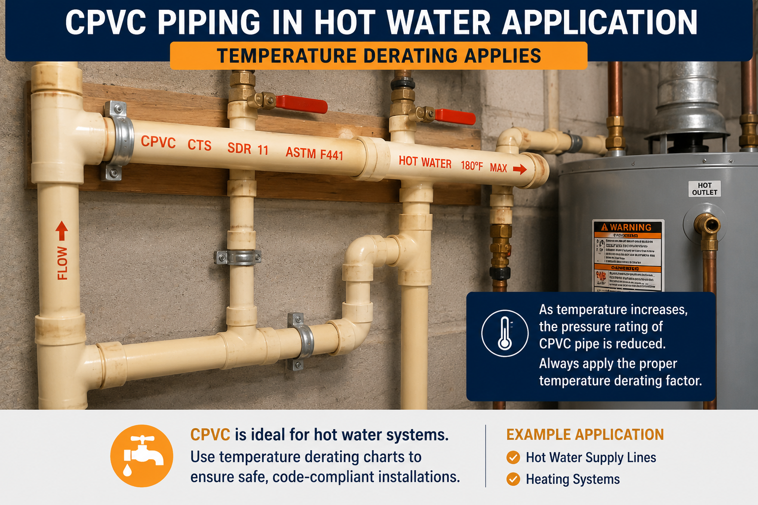
Pressure rating at 73°F is not the same as pressure rating at elevated temperature, especially for plastic pipe.
| Operating Temperature | CPVC Derating Factor |
|---|---|
| 73 to 80°F | 1.00 |
| 90°F | 0.91 |
| 100°F | 0.82 |
| 120°F | 0.65 |
| 140°F | 0.50 |
| 160°F | 0.40 |
| 180°F | 0.25 |
| 200°F | 0.20 |
Multiply the pipe’s rated working pressure at 73°F by the derating factor for the actual operating temperature. For example, 1/2 inch CPVC Schedule 40 rated at 600 psi at 73°F, operating at 140°F, has a derated working pressure of 600 x 0.50 = 300 psi. PVC uses a comparable but not identical derating table under its own standard; always use the material-specific derating factors, never a generic one-size-fits-all curve.
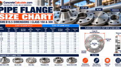
⭐⭐⭐ ASME B16.5 Flange Pressure-Temperature Classes
Flange classes are pressure-temperature ratings for flanges and flanged fittings, not universal ratings for the pipe itself.
ASME B16.5 defines pressure-temperature rating tables for flange classes 150, 300, 400, 600, 900, 1500, and 2500, covering NPS 1/2 through 24 for most classes (Class 2500 is limited to NPS 1/2 through 12). Class 150 for common carbon steel material is actually rated at 285 psi at or below 100°F, and its allowable pressure decreases as temperature rises.
| Class | Rating at ≤100°F | Rating at 300°F | Rating at 600°F |
|---|---|---|---|
| 150 | 285 psi | 230 psi | 140 psi |
| 300 | 740 psi | 655 psi | 570 psi |
| 600 | 1,480 psi | 1,310 psi | 1,135 psi |
| 900 | 2,220 psi | 1,965 psi | 1,705 psi |
| 1500 | 3,705 psi | 3,270 psi | 2,840 psi |
| 2500 | 6,170 psi | 5,450 psi | 4,730 psi |
Values shown are for Group 1.1 carbon steel material (such as ASTM A105). Different material groups have different pressure-temperature tables under the same B16.5 classes; always confirm the exact material group before using a specific value.
Class 150 vs Class 300
Class 300 is not simply “twice” Class 150; at low temperature the ratio is roughly 2.6 times, but the ratio changes with temperature since each class has its own temperature-dependent curve.
Class 600 vs Class 900
Same principle applies; compare the actual tabulated value at the specific design temperature rather than assuming a fixed multiplier between classes.
⭐⭐⭐ Fittings, Valves & Joint Pressure Rating
The complete system rating is only as good as its weakest component.
Pipe fitting pressure rating
Elbows, tees, couplings, reducers, caps, and unions must each be rated compatible with the system design pressure and temperature; a high-rated pipe does not make a lower-rated fitting acceptable.
Valve pressure rating
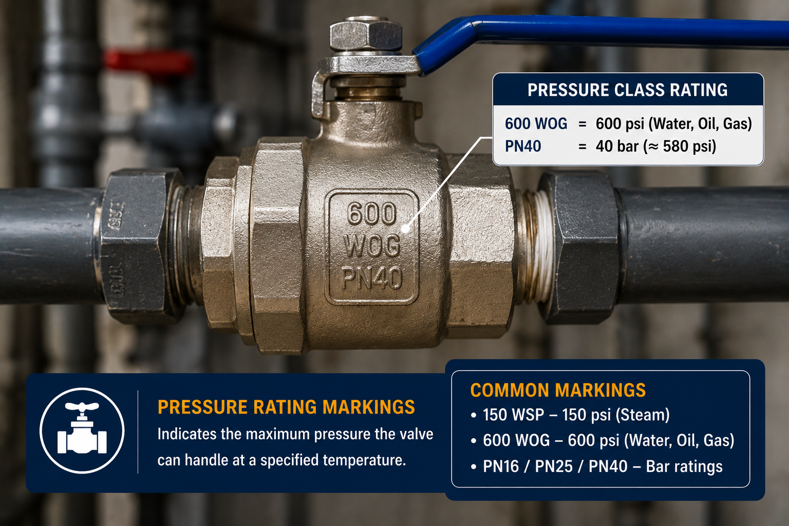
Valve class, pressure-temperature rating, material, and valve type are manufacturer-specified and must match or exceed the system’s design conditions.
Threaded pipe pressure rating
Thread type alone (such as NPT) does not establish pressure rating; the specific pipe and fitting material, size, and design basis determine the actual rating. Avoid claims like “1/2 NPT equals 3,000 psi,” which is not a valid universal statement. See the NPT Thread Chart and Pipe Thread Chart.
Flanged joint rating
System rating depends on flange class, material, temperature, bolting, gasket, and joint design together, not the pipe alone.
The pipe, fitting, valve, and flange must all be suitable for the actual design conditions. The overall system is limited by its lowest-rated component, not its highest-rated one.
⭐⭐⭐ Pipe Pressure Design Calculation Concept
Metallic pressure design is an engineering calculation defined by the applicable code, not a simple formula lookup.
A commonly referenced simplified thin-wall hoop stress relationship is approximately: Hoop stress equals Pressure times Diameter, divided by (2 times Wall Thickness). This illustrates the general relationship between these variables but is not a substitute for the applicable piping code’s actual pressure design equation, which includes allowable stress, joint efficiency, and other required factors.
Pipe diameter and pressure rating
Two pipes with the same wall thickness but different diameters cannot automatically be assigned the same pressure rating, since hoop stress increases with diameter at a fixed wall thickness and pressure.
Wall thickness required for pressure
Higher design pressure generally requires greater pressure resistance, which may involve greater wall thickness, a stronger material, a smaller diameter, or a different design and code approach, determined through the applicable calculation rather than assumption.
⭐⭐⭐ Pipe Pressure Testing & Burst Pressure
Testing verifies integrity but should never be confused with routine operation.
Hydrostatic testing
Water is commonly used as the test medium because it is largely incompressible, reducing stored energy and associated hazard compared to compressible gas if a failure occurs. Test pressure and duration are code and system specific.
Pneumatic testing
ASTM D1785 notes that some manufacturers do not allow pneumatic testing of PVC pipe because of the inherent hazards associated with testing components using compressed air or other compressed gases, since a failure releases stored energy far more suddenly and dangerously than a hydrostatic test failure. Follow the manufacturer’s specific testing guidance.
Maximum allowable working pressure
This term describes the safe long-term operating limit, distinct from nominal pressure, test pressure, and burst pressure, which are all higher-magnitude or different-purpose values.
Safety factor
The applicable code, material, and product standard determines the required design safety margin; there is no single universal safety factor that applies across every pipe material and application.
⭐⭐⭐ Corrosion & Remaining Wall Thickness
An existing pipe’s suitability can change significantly from its original rating.
Original vs remaining wall
Original nominal wall thickness minus corrosion, erosion, or pitting loss equals the remaining measured wall thickness. See the Pipe Wall Thickness Chart for original nominal values by schedule.
Evaluating remaining wall
Whether remaining wall thickness is still acceptable for continued service requires the applicable engineering or code evaluation criteria for that specific system, not a simplistic percentage rule.
Corrosion, erosion, pitting, cracks, and mechanical damage from previous service can all reduce a used pipe’s suitability below its original rating. Inspection and engineering evaluation, not the original nameplate rating, determine current fitness for continued service.
⭐⭐⭐ How to Find the Pressure Rating of a Pipe
A practical identification workflow.
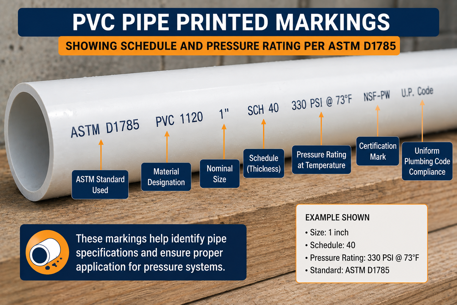
Look for printed manufacturer, material, standard designation, and size information along the pipe surface.
This determines which product data sheet or catalog applies.
Steel, stainless steel, PVC, CPVC, HDPE, copper, or another material entirely changes the applicable standard.
Confirm nominal pipe size from markings or measurement.
Confirm the specific dimensional designation used.
Establish the actual or expected service temperature.
Confirm which ASTM, ASME, or other governing standard applies to that material and product.
Look up the actual rating for that exact material, size, schedule, and temperature combination.
Confirm every connected component meets or exceeds the required rating.
The system is limited by its lowest-rated component.
⭐ Pipe Pressure Rating by Service Type
Different services carry different risk profiles and requirements.
Water
PVC, CPVC, steel, copper, and HDPE each have their own material-specific water pressure ratings; never assume one material’s rating applies to another.
Compressed air ⭐⭐
Air service can be more hazardous than water service for the same nominal pressure, particularly for plastics, since a failure releases stored compressed-gas energy suddenly. Confirm the specific product is rated and approved for compressed air/gas service.
Gas
Fuel gas piping requires the applicable gas code and product specification; do not infer gas service suitability from a generic water pipe rating.
Hydraulic systems
Hydraulic pressure, shock loading, fittings, hoses, and valves all require product-specific ratings suited to hydraulic service, which can differ from general piping.
Steam
Steam systems require the applicable piping code, considering both temperature and pressure together, along with material allowable stress; this is far beyond a simple schedule lookup.
Construction ⭐⭐⭐
Concrete pumps, water lines, compressed air equipment, hydraulic systems, and temporary piping on construction sites each require confirming the specific product’s rating for its actual service, not assuming based on appearance.
⭐⭐⭐ Pipe Pressure Rating Visual Guide
Original diagrams explaining pressure factors, the pressure/burst distinction, and flange classes.
⭐⭐⭐ Pipe Pressure Rating Worked Examples
These examples show the reasoning process across different materials and conditions.
1. PVC Schedule 40
2. PVC Schedule 80
3. Steel Schedule 40
4. Flange Class 150
5. Used Pipe With Wall Loss
⭐⭐⭐ Common Pipe Pressure Rating Mistakes
Most pressure rating errors trace back to one of these misunderstandings.
❌ Assuming Schedule 40 has one universal PSI rating
Only certain plastic products have standardized published ratings; steel requires calculation.
❌ Assuming thicker pipe automatically has a specific pressure rating
Thickness is one input among several required factors.
❌ Confusing working pressure with burst pressure
Burst pressure is a failure point, never an operating target.
❌ Ignoring temperature
Pressure rating changes significantly with temperature, especially for plastics.
❌ Ignoring material
Steel, stainless, PVC, CPVC, and HDPE each require their own standard.
❌ Ignoring corrosion
Remaining wall thickness after service life can be well below original nominal thickness.
❌ Using PVC ratings for CPVC
Different materials, different governing standards, different actual ratings.
❌ Using steel ratings for stainless steel
Different material properties require separate design calculation.
❌ Confusing flange class with pipe pressure rating
Flange classes rate the flange and flanged fitting, not the pipe body.
❌ Ignoring fittings and valves
The system is limited by its lowest-rated component.
❌ Using a generic internet PSI chart for system design
Always use the applicable manufacturer data or design code for actual projects.
❌ Performing unsafe pneumatic testing
Some manufacturers explicitly prohibit compressed-gas testing due to hazard; follow their guidance.
Frequently Asked Questions
📄 Download Pipe Pressure Rating Chart PDF
This PDF is a proper engineering reference, not a screenshot of the page. Use the print button to create a print-ready or downloadable version.
Cite or Embed This Chart
Copy the page-wide citation to reference the complete Pipe Pressure Rating Chart.