Beam Deflection Chart: L/360, L/240, L/180 and L/480 by Span
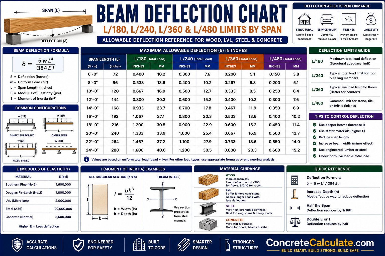
Beam Deflection Chart
L/360, L/240, L/180 and L/480 by Span
A detailed deflection reference explaining allowable deflection ratios, actual deflection formulas, modulus of elasticity, moment of inertia, and how deflection differs from strength.
Table of Contents
- Quick Reference Chart
- What Is Beam Deflection?
- Deflection vs Beam Strength
- Beam Deflection Limits Chart
- L/180 Deflection Chart
- L/240 Deflection Chart
- L/360 Deflection Chart
- L/480 Deflection Chart
- Beam Deflection by Span
- Beam Deflection by Beam Size
- Beam Deflection by Load
- Uniform Load vs Point Load Deflection
- Deflection Under Center Point Load
- Deflection Under Uniform Load
- Deflection for Multiple Point Loads
- Beam Deflection Formula
- Formula for Uniform Load
- Formula for Point Load
- Maximum Beam Deflection
- Deflection and Modulus of Elasticity
- Deflection and Moment of Inertia
- Beam Depth vs Deflection
- Beam Width vs Deflection
- Beam Span vs Deflection
- Beam Load vs Deflection
- Deflection and Support Conditions
- Simply Supported Beam Chart
- Cantilever Beam Deflection
- Continuous Beam Deflection
- Deflection by Material
- Wood Beam Deflection Chart
- LVL Beam Deflection Chart
- Glulam Beam Deflection Chart
- Steel Beam Deflection Chart
- Concrete Beam Deflection Chart
- Live Load vs Total Load Deflection
- Deflection and Dead Load
- Deflection and Live Load
- Deflection and Long Term Creep
- Deflection and Camber
- Deflection and Floor Vibration
- Deflection and Cracking
- Deflection and Building Finishes
- Deflection vs Beam Span
- Deflection vs Beam Size
- Deflection vs LVL Size
- Deflection vs Steel Beam Size
- Visual Deflection Guide
- How to Read a Deflection Chart
- Calculate Allowable Deflection
- Calculate Actual Deflection
- Worked Examples
- Deflection Conversion Chart
- Chart for Common Spans
- Common Deflection Mistakes
- FAQ, 15 Questions
- Download PDF
Beam Deflection Chart, Quick Reference
Maximum allowable deflection equals beam span divided by the deflection ratio. Convert span to inches first, then divide by the ratio (180, 240, 360, or 480) to get allowable deflection in inches.
| Beam span | L/180 | L/240 | L/360 | L/480 |
|---|---|---|---|---|
| 6 ft | 3/8 in | 5/16 in | 3/16 in | 1/8 in |
| 8 ft | 9/16 in | 3/8 in | 1/4 in | 3/16 in |
| 10 ft | 11/16 in | 1/2 in | 1/3 in | 1/4 in |
| 12 ft | 13/16 in | 5/8 in | 3/8 in | 5/16 in |
| 14 ft | 15/16 in | 11/16 in | 7/16 in | 3/8 in |
| 16 ft | 1 1/16 in | 13/16 in | 9/16 in | 3/8 in |
| 18 ft | 1 3/16 in | 7/8 in | 5/8 in | 7/16 in |
| 20 ft | 1 5/16 in | 1 in | 11/16 in | 1/2 in |
| 24 ft | 1 5/8 in | 1 3/16 in | 13/16 in | 5/8 in |
| 30 ft | 2 in | 1 1/2 in | 1 in | 3/4 in |
What Is Beam Deflection?
Definition
Deflection is the vertical displacement of a beam from its original, unloaded position, caused by the elastic bending response of the material under applied load.
Downward deflection
Most beams under gravity load deflect downward at midspan or at the point of load application, within the elastic range of the material.
Upward camber
Some beams are manufactured or installed with a slight upward curve, called camber, intended to offset a portion of expected dead load deflection.
Elastic vs permanent deformation
Elastic deflection recovers when load is removed. Permanent deformation occurs only if the material is stressed beyond its elastic limit, which is a strength and safety issue, not ordinary serviceability deflection.
Deflection is a serviceability consideration, meaning it addresses comfort, appearance, and finish performance rather than the immediate risk of structural failure, though it is checked as a required part of a complete beam design.
Beam Deflection vs Beam Strength
These are two separate structural checks, and a beam must satisfy both.
| Check | Question answered | Governing property |
|---|---|---|
| Strength (bending and shear) | Can the beam safely carry the load without breaking? | Bending design value (Fb) and shear design value (Fv) |
| Deflection (stiffness) | Does the beam bend an acceptable amount while carrying the load? | Modulus of elasticity (E) and moment of inertia (I) |
Beam Deflection Limits Chart
| Ratio | Meaning | Commonly referenced context |
|---|---|---|
| L/180 | Allowable deflection equals span divided by 180 | Referenced in some code tables for rafters without an attached finished ceiling |
| L/240 | Allowable deflection equals span divided by 240 | Referenced for general structural members and certain roof conditions in some code tables |
| L/360 | Allowable deflection equals span divided by 360 | Commonly referenced for floors and plastered construction in code tables |
| L/480 | Allowable deflection equals span divided by 480 | May be specified for sensitive finishes or specific project requirements |
| Other project specific ratios | Varies | Determined by the architect, engineer, manufacturer, or owner requirement for the specific project |
Reference building code tables commonly list allowable deflection as L/360 for floors and plastered construction, L/180 for rafters with a slope greater than 3/12 and no finished ceiling attached, and L/240 for most other structural members, always subject to the applicable adopted code edition.
L/180 Deflection Chart
L/180 is a less restrictive ratio sometimes applied to members such as rafters without an attached finished ceiling. Always verify the applicable code and design condition before applying this ratio to a specific member.
| Span | Allowable deflection at L/180 |
|---|---|
| 6 ft | 3/8 in |
| 8 ft | 9/16 in |
| 10 ft | 11/16 in |
| 12 ft | 13/16 in |
| 14 ft | 15/16 in |
| 16 ft | 1 1/16 in |
| 18 ft | 1 3/16 in |
| 20 ft | 1 5/16 in |
| 24 ft | 1 5/8 in |
| 30 ft | 2 in |
L/240 Deflection Chart
| Span | Allowable deflection at L/240 |
|---|---|
| 6 ft | 5/16 in |
| 8 ft | 3/8 in |
| 10 ft | 1/2 in |
| 12 ft | 5/8 in |
| 14 ft | 11/16 in |
| 16 ft | 13/16 in |
| 18 ft | 7/8 in |
| 20 ft | 1 in |
| 24 ft | 1 3/16 in |
| 30 ft | 1 1/2 in |
This ratio is commonly referenced for general structural members and for certain total load conditions, subject to the applicable code.
L/360 Deflection Chart
L/360 is one of the most frequently referenced deflection ratios, particularly for floor systems.
| Span | Allowable deflection at L/360 |
|---|---|
| 6 ft | 3/16 in |
| 8 ft | 1/4 in |
| 10 ft | 1/3 in |
| 12 ft | 3/8 in |
| 14 ft | 7/16 in |
| 16 ft | 9/16 in |
| 18 ft | 5/8 in |
| 20 ft | 11/16 in |
| 24 ft | 13/16 in |
| 30 ft | 1 in |
L/480 Deflection Chart
| Span | Allowable deflection at L/480 |
|---|---|
| 6 ft | 1/8 in |
| 8 ft | 3/16 in |
| 10 ft | 1/4 in |
| 12 ft | 5/16 in |
| 14 ft | 3/8 in |
| 16 ft | 3/8 in |
| 18 ft | 7/16 in |
| 20 ft | 1/2 in |
| 24 ft | 5/8 in |
| 30 ft | 3/4 in |
Beam Deflection by Span
Allowable deflection scales directly with span, while actual deflection under a real load scales much faster, with span raised to the third or fourth power depending on load type. This range from 6 to 32 feet reflects common residential and light commercial wood beam spans.
| Span | L/360 allowable (reference) | Relative actual deflection trend (uniform load, same beam) |
|---|---|---|
| 6 ft | 3/16 in | Baseline |
| 8 ft | 1/4 in | About 3.2x baseline |
| 10 ft | 1/3 in | About 7.7x baseline |
| 12 ft | 3/8 in | About 16x baseline |
| 16 ft | 9/16 in | About 50x baseline |
| 20 ft | 11/16 in | About 123x baseline |
| 24 ft | 13/16 in | About 256x baseline |
| 28 ft | 15/16 in | About 474x baseline |
| 32 ft | 1 1/16 in | About 809x baseline |
The relative actual deflection trend illustrates the span to the fourth power relationship for a uniformly loaded simply supported beam with unchanged size, material, and load per foot, holding all other variables constant for illustration only.
Beam Deflection by Beam Size
Beam size alone does not determine deflection. It also depends on span, load, modulus of elasticity, moment of inertia, and support conditions.
| Nominal size | Actual depth (in) | Relative moment of inertia at same width |
|---|---|---|
| 2×6 | 5.5 | Baseline |
| 2×8 | 7.25 | About 2.3x baseline |
| 2×10 | 9.25 | About 4.8x baseline |
| 2×12 | 11.25 | About 8.6x baseline |
| 2×14 | 13.25 | About 14x baseline |
| 4×6 | 5.5 | Baseline at 2x this width |
| 4×8 | 7.25 | About 2.3x that baseline |
| 4×10 | 9.25 | About 4.8x that baseline |
| 4×12 | 11.25 | About 8.6x that baseline |
| 6×6 | 5.5 | Baseline at 3x this width |
| 6×8 | 7.5 | About 2.5x that baseline |
| 6×10 | 9.5 | About 5.2x that baseline |
| 6×12 | 11.5 | About 9.2x that baseline |
Beam Deflection by Load
Numerical deflection values are only meaningful under clearly stated assumptions of span, size, material, and support condition. The categories below are organizational reference points, not universal deflection values.
| Uniform load | Planning implication |
|---|---|
| 500 lb/ft | Lighter loading condition, still requires a full deflection check for the specific beam |
| 1,000 lb/ft | Common moderate residential beam loading range |
| 1,500 lb/ft | Higher loading, deflection more likely to govern over strength |
| 2,000 lb/ft | Deeper section or stiffer material often needed to control deflection |
| 2,500 lb/ft | Engineered wood, steel, or professional design commonly evaluated |
| 3,000 lb/ft | Professional structural design and deflection verification strongly recommended |
Uniform Load vs Point Load Deflection
Two beams carrying the same total load can experience very different maximum deflection depending on how that load is distributed.
For a simply supported beam with the same total load, the uniform load case and the center point load case produce different deflection coefficients, 5/384 versus 1/48, and different span exponents in the general form, so they should never be assumed equal.
Beam Deflection Under Center Point Load
For a simply supported beam with a single concentrated load at midspan, maximum deflection occurs directly under the load, at the center of the span, and is calculated using the point load formula shown in the formula section below.
Beam Deflection Under Uniform Load
For a simply supported beam with a uniformly distributed load along its full length, maximum deflection occurs at the center of the span, calculated using the uniform load formula shown below.
Beam Deflection for Multiple Point Loads
Beams supporting multiple posts, walls, trusses, or other beams experience combined deflection effects from each individual point load and its specific location. These cases require superposition of individual load effects or direct structural analysis software rather than a single simplified formula, since the location and magnitude of each load changes the result.
Beam Deflection Formula
Deflection depends on load, span, modulus of elasticity, moment of inertia, and support condition together. Different support and load combinations require their own specific formula rather than one universal equation for every case.
| Case | Maximum deflection formula | Location |
|---|---|---|
| Simply supported, uniform load | 5wL^4 / (384EI) | Midspan |
| Simply supported, center point load | PL^3 / (48EI) | Midspan |
| Cantilever, end point load | PL^3 / (3EI) | Free end |
| Fixed end, center point load | PL^3 / (192EI) | Midspan |
These are the standard closed form deflection equations for common support and load cases from mechanics of materials references. w is uniform load per unit length, P is a concentrated point load, L is span, E is modulus of elasticity, and I is moment of inertia.
Beam Deflection Formula for Uniform Load
For the standard simply supported beam case under a uniformly distributed load, delta is deflection, w is the uniform load per unit length, L is span, E is modulus of elasticity, and I is moment of inertia. Deflection increases with the fourth power of span, making span the single most sensitive variable.
Beam Deflection Formula for Point Load
For a simply supported beam with a center point load, delta is deflection, P is the point load, L is span, E is modulus of elasticity, and I is moment of inertia. Deflection increases with the third power of span for this load case.
Maximum Beam Deflection
Maximum deflection occurs at midspan for a symmetrically loaded, simply supported beam, whether the load is uniform or a centered point load. For asymmetrical loading, such as an off-center point load or multiple unevenly spaced loads, maximum deflection can occur away from midspan and generally requires either superposition of standard cases or direct structural analysis.
Beam Deflection and Modulus of Elasticity (E)
Modulus of elasticity, E, is a direct measure of material stiffness.
Different materials and even different species and grades of the same material have different E values, which is why identical beam dimensions under identical loads can deflect differently depending on what the beam is made of.
Beam Deflection and Moment of Inertia (I)
Moment of inertia describes how a cross section’s shape resists bending, and it depends heavily on cross sectional geometry.
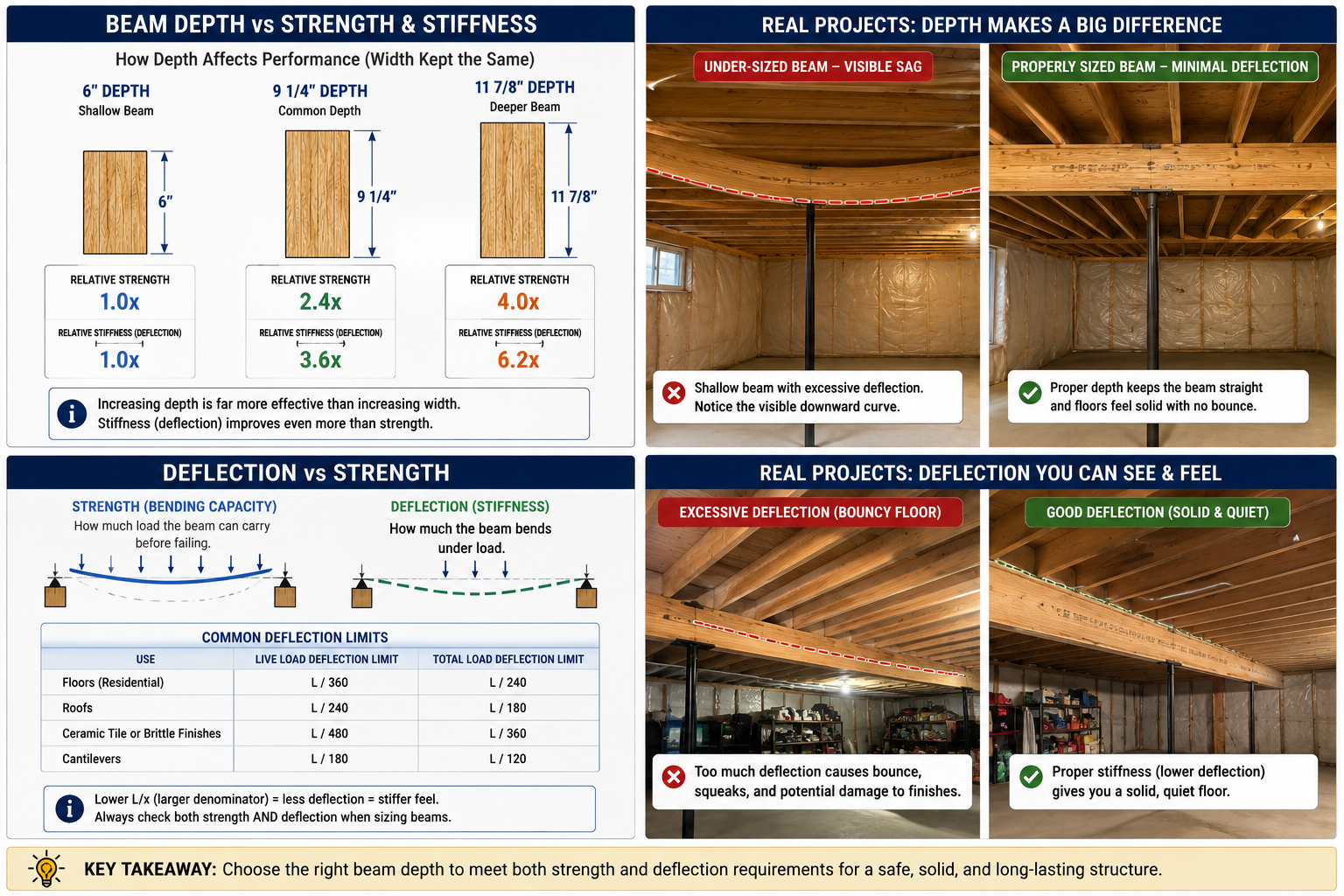
Because moment of inertia scales with the cube of depth (h) but only linearly with width (b), increasing beam depth has a dramatically larger effect on stiffness and deflection resistance than increasing width by the same amount.
Beam Depth vs Deflection
Because moment of inertia for a rectangular section increases with the cube of depth, a modest increase in beam depth can substantially reduce deflection under the same span and load, generally making depth the most efficient variable to adjust when deflection governs a design.
Beam Width vs Deflection
Increasing beam width also increases moment of inertia, but only linearly rather than cubically. Doubling width roughly doubles moment of inertia at a given depth, while doubling depth increases moment of inertia roughly eightfold, so width increases are a far less efficient way to control deflection compared with depth increases.
Beam Span vs Deflection
Deflection becomes increasingly important as span increases because of the strong nonlinear relationship between span and deflection.
For a uniformly loaded simply supported beam, deflection is proportional to span to the fourth power, meaning a doubling of span, with everything else held constant, increases deflection by a factor of sixteen. This relationship connects directly to sizing decisions covered in the Beam Size Chart and the LVL Span Chart, where longer spans commonly require deeper or stiffer members specifically to control deflection.
Beam Load vs Deflection
Increasing load generally increases deflection, since load appears directly in the numerator of every standard deflection formula. The exact relationship, whether linear with total load or scaled differently for distributed versus concentrated loading, depends on the specific structural configuration and load case involved.
Beam Deflection and Support Conditions
| Support condition | General effect on deflection |
|---|---|
| Simply supported | Baseline reference case, free rotation at both ends |
| Fixed | End restraint against rotation significantly reduces deflection compared with simply supported, for the same span and load |
| Continuous (multiple spans) | Interior supports and negative moments generally reduce deflection compared with an equivalent simple span |
| Cantilever | Behaves very differently from a simply supported beam, with maximum deflection at the free end rather than midspan |
Support conditions significantly affect both the magnitude and location of maximum deflection, so the correct formula must always match the actual support condition, not be assumed from a simply supported case.
Simply Supported Beam Deflection Chart
The simply supported beam, with a pin support at one end and a roller support at the other, is the primary calculation model used for the simplest deflection examples on this page, including the uniform load and center point load formulas shown above. It is also the most common condition encountered in typical residential floor and roof beam applications.
Cantilever Beam Deflection Chart
For a simple reference case only, a cantilever with a point load at the free end deflects according to PL^3 / (3EI), while a cantilever with a uniform load along its length deflects according to a related but different formula. Both require the exact length, load, and fixity condition to apply correctly.
Continuous Beam Deflection
A continuous beam spans over three or more supports and develops negative moments over the interior supports, which generally reduces deflection compared with a series of independent simple spans carrying the same load. The exact reduction depends on the number of spans, their relative lengths, and the specific loading pattern, so a universal value cannot be given without defining the exact support and loading arrangement.
Beam Deflection by Material
| Material | Relative stiffness characteristic | Design value source |
|---|---|---|
| Solid sawn lumber | Moderate, species and grade dependent | NDS Supplement reference design values |
| LVL | Higher and more consistent than typical sawn lumber | Manufacturer specific design values |
| Glulam | High, varies by combination symbol | Manufacturer or NDS glulam design values |
| PSL | High, varies by product | Manufacturer specific design values |
| Steel | Very high and highly consistent | Standard steel E value, approximately 29,000,000 psi |
| Concrete | Moderate, reduced by cracking | Concrete design codes, cracked and uncracked section properties |
| Reinforced concrete | Effective stiffness depends on reinforcement and cracking state | Concrete design codes, effective moment of inertia methods |
Wood Beam Deflection Chart
Wood beam deflection depends on species, grade, the resulting E value, beam size, span, and load. Reference design values for sawn lumber, glulam, structural composite lumber, and other wood structural products are published in current design specification documents, and species and grade selection directly changes the E value used in every deflection calculation.
LVL Beam Deflection Chart
LVL deflection depends on depth, width, E value, span, load, and number of plies.
Glulam Beam Deflection Chart
Glulam stiffness depends on the specific combination symbol and manufacturer design values, since glulam beams are manufactured from laminated sawn lumber with properties that vary by layup. Glulam is frequently selected for long span applications specifically because of its high and predictable stiffness relative to comparable solid sawn sections.
Steel Beam Deflection Chart
Steel beam deflection follows the same standard formulas as wood, but with a much higher and more consistent E value.
| Variable | Steel specific consideration |
|---|---|
| Modulus of elasticity (E) | Approximately 29,000,000 psi for structural steel, several times higher than typical wood products |
| Moment of inertia (I) | Depends on the specific rolled section shape, published in steel section property tables |
| Section shape | Wide flange, channel, and other shapes have very different I values even at similar depths |
See the Steel Beam Size Chart for steel section specific information relevant to deflection calculations.
Concrete Beam Deflection Chart
Beam Deflection, Live Load vs Total Load
These represent two different deflection checks that may use different allowable ratios.
| Deflection basis | Loads included |
|---|---|
| Live load deflection | Variable, non-permanent loads only, such as occupants, furniture, or snow |
| Total load deflection | Dead load plus live load combined |
The applicable criterion and ratio depend on the structural design and code context, and general span table guidance distinguishes strength loading from deflection considerations, noting that the governing load combination depends on the specific application rather than one universal rule.
Beam Deflection and Dead Load
Dead load contributing to deflection includes the beam’s own self weight, flooring, roofing, wall weight, ceiling finishes, and other permanent fixtures. Because dead load is present continuously, it contributes to both immediate and long term deflection, and pre-camber is sometimes used specifically to offset anticipated dead load deflection.
Beam Deflection and Live Load
Live load deflection results from variable, non-permanent loads such as occupants, furniture, and storage. Because live load is not always present at its maximum design value, live load deflection is often checked against a separate, sometimes more restrictive ratio than total load deflection.
Beam Deflection and Long Term Creep
Deflection is not always a single, fixed value measured immediately after loading.
Immediate deflection
The elastic deflection that occurs as soon as load is applied, calculated using standard formulas.
Long term deflection
Additional deflection that develops gradually over time under sustained load, particularly relevant for wood and concrete.
Creep and moisture
Wood members can experience additional long term deflection from creep and moisture content changes under sustained load, beyond the initial elastic deflection.
Beam Deflection and Camber
Camber is an intentional upward curve built into a beam before it carries any load.
Some engineered beams, particularly longer span members, are manufactured with camber so that the beam approaches a level position once dead load deflection occurs in service. Camber offsets a portion of expected dead load deflection but does not eliminate the need for a full structural deflection design check under all applicable loads, since live load deflection still occurs on top of the cambered starting position.
Beam Deflection and Floor Vibration
Floor stiffness affects walking vibration and overall floor comfort, particularly for longer spans. A floor beam that satisfies a standard deflection limit can still feel bouncy or springy under foot traffic if vibration performance was not separately considered, since vibration serviceability and static deflection limits address related but distinct comfort concerns.
Beam Deflection and Cracking
Excessive beam movement can directly damage attached building finishes.
Movement beyond the finish material’s tolerance can contribute to drywall cracking, plaster cracking, tile cracking or debonding, flooring problems, and doors or windows binding or failing to operate properly. Deflection limits in building codes are specifically intended, in part, to help control this kind of finish related cracking and damage by limiting how much the supporting structure is allowed to move.
Beam Deflection and Building Finishes
| Finish type | General sensitivity to deflection |
|---|---|
| Plaster | High, prone to cracking with limited movement |
| Drywall | Moderate to high, can crack at joints and corners |
| Tile | High, prone to cracking or debonding |
| Stone | High, brittle and sensitive to movement |
| Wood flooring | Moderate, more tolerant but can still show gaps or squeaks |
Beam Deflection vs Beam Span
Two beams with the same span can have very different deflection depending on their other properties. For example, Beam A with a smaller depth, lower E value, and higher load will deflect considerably more than Beam B with greater depth, higher E value, and the same span, even though the span itself is identical for both.
Beam Deflection vs Beam Size
Increasing beam depth is often the most effective single way to reduce deflection, because moment of inertia scales with the cube of depth for a rectangular section. See the Beam Size Chart for depth options and how depth interacts with span, load, and material selection.
Beam Deflection vs LVL Size
Deeper LVL members can provide significantly greater stiffness than shallower members of the same width, following the same depth cubed relationship as solid sawn lumber, combined with LVL’s typically higher and more consistent E value. See the LVL Span Chart for manufacturer specific depth and design value information.
Beam Deflection vs Steel Beam Size
Steel beam deflection depends on the interaction of moment of inertia, the steel modulus of elasticity, section shape, span, and load. Because steel’s E value is far higher than wood or most engineered wood products, a steel section can often achieve lower deflection at a shallower depth than an equivalent wood beam. See the Steel I Beam Chart for section specific properties.
Visual Beam Deflection Guide
1. Deflection diagram
Before load and after load, included above in the What Is Beam Deflection section.
2. L/360 diagram
Add an SVG showing a labeled span with its calculated allowable deflection distance marked at midspan.
3. Uniform load deflection
Shown conceptually above in the uniform versus point load diagram, with maximum deflection at midspan.
4. Center point load
Add an SVG showing a single point load and the resulting maximum deflection directly beneath it.
5. Cantilever deflection
Add an SVG showing a fixed support at one end and a free end with maximum deflection at the tip.
6. Beam depth comparison
Shallow versus deep beam, included above in the Beam Depth vs Deflection section.
7. Beam load path
Add an SVG showing floor to joists to beam to posts to foundation, consistent with the Beam Size Chart diagram.
8. Deflection vs strength
Add an SVG showing a beam labeled as strong enough but too flexible, to visually reinforce that these are separate checks.
How to Read a Beam Deflection Chart
Geometry and material
Beam span, beam size, material, and E value.
Loading
Load magnitude, load type, and support condition.
Limits
The applicable deflection limit and the resulting maximum allowable deflection.
Actual result
The actual calculated deflection compared against that allowable value.
How to Calculate Allowable Beam Deflection
How to Calculate Actual Beam Deflection
Beam Deflection Worked Examples
1. Ten foot beam at L/360
Allowable deflection equals 120 inches divided by 360, or about one third of an inch, calculated as shown in the allowable deflection section above.
2. Twelve foot beam at L/360
Allowable deflection equals 144 inches divided by 360, or three eighths of an inch, illustrating how allowable movement grows directly with span.
3. Sixteen foot beam at L/360
Allowable deflection equals 192 inches divided by 360, or nine sixteenths of an inch, showing the continued linear growth in allowable movement as span increases.
4. Same span, different depths
Holding span, load, and material constant, a deeper beam has a substantially higher moment of inertia and therefore less actual deflection than a shallower beam, per the depth cubed relationship.
5. Same beam, different loads
Holding beam size, span, and material constant, increasing the applied load increases actual deflection proportionally under the standard formulas, since load appears directly in the numerator.
6. Uniform load vs center point load
For the same beam and span, a uniform load case uses the 5wL^4/384EI formula while a center point load case uses PL^3/48EI, producing different actual deflection results even for comparable total load magnitude.
Beam Deflection Conversion Chart
| Conversion | Formula |
|---|---|
| Feet to inches | Multiply feet by 12 |
| Inches to feet | Divide inches by 12 |
| L/180 allowable deflection | (Span in inches) / 180 |
| L/240 allowable deflection | (Span in inches) / 240 |
| L/360 allowable deflection | (Span in inches) / 360 |
| L/480 allowable deflection | (Span in inches) / 480 |
Beam Deflection Chart for Common Spans
A compact contractor reference combining all four common ratios in one table, matching the quick reference chart at the top of this page.
| Span | L/180 | L/240 | L/360 | L/480 |
|---|---|---|---|---|
| 6 ft | 3/8 in | 5/16 in | 3/16 in | 1/8 in |
| 8 ft | 9/16 in | 3/8 in | 1/4 in | 3/16 in |
| 10 ft | 11/16 in | 1/2 in | 1/3 in | 1/4 in |
| 12 ft | 13/16 in | 5/8 in | 3/8 in | 5/16 in |
| 14 ft | 15/16 in | 11/16 in | 7/16 in | 3/8 in |
| 16 ft | 1 1/16 in | 13/16 in | 9/16 in | 3/8 in |
| 18 ft | 1 3/16 in | 7/8 in | 5/8 in | 7/16 in |
| 20 ft | 1 5/16 in | 1 in | 11/16 in | 1/2 in |
| 24 ft | 1 5/8 in | 1 3/16 in | 13/16 in | 5/8 in |
| 30 ft | 2 in | 1 1/2 in | 1 in | 3/4 in |
Common Beam Deflection Mistakes
Confusing deflection with strength
These are separate checks; passing one does not guarantee passing the other.
Using the wrong L/X limit
The applicable ratio depends on the specific application and code, not a fixed universal value.
Ignoring span or E
Both have an outsized effect on deflection and cannot be assumed constant across projects.
Ignoring moment of inertia
Section shape and depth strongly affect I and therefore deflection.
Wrong formula for load type
Using a point load formula for uniform loading, or the reverse, produces an incorrect result.
Ignoring support conditions
Simply supported, fixed, continuous, and cantilever cases all require different formulas.
Ignoring long term creep
Sustained loading, especially in wood, can add deflection beyond the initial elastic value.
Ignoring finishes or vibration
A code minimum deflection limit does not guarantee acceptable finish performance or floor comfort.
Assuming stronger means stiffer
A beam can be strong enough to avoid failure yet still deflect excessively.
Using generic LVL values
Always use the specific manufacturer’s published design values instead of an assumed number.
Frequently Asked Questions
Related Calculators and Charts
Download Beam Deflection Chart PDF
Use the print button to generate a current, print ready PDF. The printable reference includes the quick L/180, L/240, L/360 and L/480 table, the common span deflection chart, deflection formulas, a uniform load example, a point load example, the E and I explanation, the beam depth comparison, wood beam guidance, LVL guidance, steel beam guidance, the deflection versus strength diagram, worked examples, and a contractor quick reference sheet.