Purlin Spacing Chart – Roof Purlin Spacing, Tributary Load & Panel Span
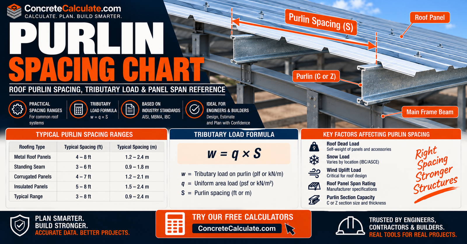
Purlin Spacing Chart
Roof Purlin Spacing, Tributary Load & Panel Span
Example purlin spacing ranges, the w=qS tributary load conversion, and guidance on how roof-panel span, purlin capacity, snow, and wind uplift together control the maximum allowable purlin spacing for U.S. metal roofs.
 Reviewed by Muhammad Ramzan Babar, PhD Researcher (Plasma Physics) & Calculator Developer, View Profile
There is no universal 4-ft, 5-ft, or 5-ft-6-in. purlin spacing rule
Manufacturer systems often use those ranges, but only under specific roof-panel, loading, and approval conditions. Nucor’s own UL90-rated roof documentation limits purlin spacing to a maximum of 5 ft for that specific rated assembly. These are product and system examples, not general structural rules for every roof.
Purlin Spacing Chart, Quick Reference
These are reference examples with conditions attached, not a prescriptive universal table.
Typical Metal Roof Purlin Spacing Reference
| Example Spacing | Common Context | What Must Be Verified |
|---|---|---|
| 2 ft O.C. | Closely spaced roof framing, lighter panels, special conditions | Panel capacity, purlin size, loads |
| 3 ft O.C. | Reduced tributary width | Panel and purlin load tables |
| 4 ft O.C. | Common system spacing in some metal buildings | Exact roof system |
| 5 ft O.C. | Common system spacing in some metal-building products | Panel approval, purlin capacity |
| 5 ft 6 in. O.C. | Used in some engineered systems | Product/system-specific limits |
| 6 ft+ O.C. | Possible for selected panels/systems | Must be specifically engineered |
These are reference spacing ranges, not universally allowable values. The governing spacing is the smallest spacing allowed by the roof panel, purlin structural capacity, connections, restraint system, and project loads.
Spacing vs Tributary Load Quick Chart
For illustrative purposes only, at a roof pressure of q = 20 psf:
| Purlin Spacing | Line Load, w = qS |
|---|---|
| 2 ft | 40 plf |
| 3 ft | 60 plf |
| 4 ft | 80 plf |
| 5 ft | 100 plf |
| 6 ft | 120 plf |
This is an illustrative calculation at a single assumed pressure, not a design load recommendation. It shows why increasing spacing directly increases the load on each purlin.
What Is Purlin Spacing?
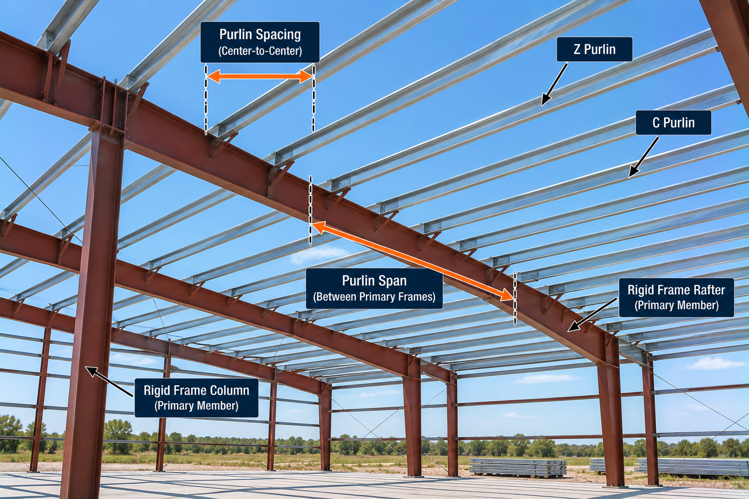
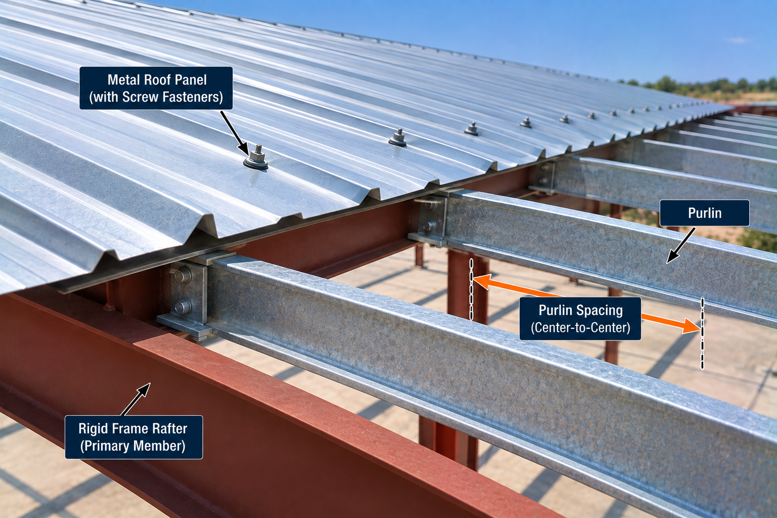
The center-to-center distance between adjacent parallel roof purlins.
Purlin spacing is usually expressed in inches on center, feet on center, or millimeters center-to-center.
On-Center Spacing
“O.C.” means on center. A spacing of 5 ft O.C. means the centerline of one purlin is 5 ft from the centerline of the next adjacent purlin, not the clear gap between the two members.
Purlin Spacing vs Purlin Span
One of the most important distinctions on this page.
| Term | Definition | What It Controls |
|---|---|---|
| Purlin Spacing | Distance between adjacent purlins | Tributary load on each purlin |
| Purlin Span | Distance along the purlin between primary supports | Bending, shear, and deflection demand |
These should never be confused. Spacing controls the tributary load carried by a purlin through w = qS, while span controls how that load produces bending moment, shear, and deflection along the member’s length.
Why Purlin Spacing Matters
Spacing affects far more than just how many purlins fit on the roof.
Spacing directly affects the load on each purlin, the required roof-panel span, the total number of purlins, steel tonnage, connection quantity, roof stiffness, erection cost, deflection, wind-uplift demand, and snow-load distribution. Wider spacing can reduce member count but increases panel span and load per purlin and per connection, so wider spacing is not automatically cheaper once the full system is accounted for.
What Determines Purlin Spacing?
Purlin spacing cannot be selected from roof size alone.
| Factor | Why It Matters |
|---|---|
| Roof Panel Allowable Span | Panel must itself span the selected spacing |
| Purlin Section Size | Determines available section properties |
| Purlin Thickness | Directly affects stiffness and strength |
| Purlin Span | Combines with spacing to set total demand |
| Dead Load | Permanent roof weight per unit area |
| Roof Live Load | Code-minimum maintenance/construction load |
| Snow and Drift | Can govern gravity design in many U.S. regions |
| Wind Uplift | Reversed loading with different restraint behavior |
| Roof Slope | Affects on-slope layout and load resolution |
| Standing-Seam vs Through-Fastened Panel | Different restraint and clip/fastener assumptions |
| C vs Z Purlin | Different symmetry, restraint, and continuity behavior |
| Simple vs Continuous Purlins | Continuity changes internal moment and deflection |
| Bracing / Restraint | Affects lateral stability and torsion |
| Deflection Criteria | Serviceability limit separate from strength |
| Connections | Must transfer the resulting reaction and uplift forces |
Roof Panel Span as a Purlin-Spacing Limit
Arguably the page’s strongest practical section.
The roof panel spans between purlins, so for ordinary repetitive roof framing, panel span is approximately equal to purlin spacing. Panel allowable span depends on panel profile, metal thickness, steel strength, fastening, support condition, positive pressure, negative or uplift pressure, and the number of spans the panel covers. Manufacturer load-table documentation demonstrates this principle directly: published panel allowable capacity changes with span, and manufacturer notes explicitly state that the lowest allowable load between panel design and connection strength must control the design.
Panel Span ≈ Purlin Spacing
For ordinary repetitive roof framing, treat the roof panel’s allowable span rating as a hard ceiling on purlin spacing before checking the purlin itself.
Through-Fastened vs Standing-Seam Purlin Spacing
Panel attachment type changes both the load path and the restraint the panel provides to the purlin.
| Panel Type | Purlin Spacing Relationship | Must Check |
|---|---|---|
| Exposed fastener (through-fastened) | Panel spans between purlins | Positive and uplift loads |
| Standing seam | Clips occur at purlin lines | Clip/panel span/load approval |
| Insulated metal panel | Panel acts as a spanning panel | Panel thickness and connection |
| Structural roof panel | Product-specific | Tested load-span table |
For dedicated panel-span data, see the Metal Roof Panel Span Chart.
Through-Fastened Roof Purlin Spacing
Through-fastened panels attach directly to the purlins with screws. Current national roof-framing design guidance notes that through-fastened panels can provide direct lateral and rotational restraint to supporting purlins. Spacing therefore has two simultaneous effects: it sets the panel span, and it sets the tributary width and load on the purlin. There is no universal spacing value that applies to every through-fastened roof.
Standing-Seam Roof Purlin Spacing
Standing-seam panels attach through clips rather than direct screws through the panel field. Clip details and panel profiles affect the amount of lateral restraint provided to the purlins, and sliding clips can reduce that restraint relative to more direct attachment.
Fixed Clips
Fixed clips attach the panel rigidly at that point, which can provide more direct restraint to the purlin below.
Sliding Clips
Sliding clips allow the panel to move for thermal expansion, which can reduce the lateral restraint transferred to the purlin compared with a fixed connection.
Why Clip Spacing Usually Follows Purlin Lines
Clips are typically located at purlin lines so the panel’s fastening pattern lines up with available structural support. Purlin spacing must therefore conform to the roof manufacturer’s approved span and clip configuration rather than an assumed generic spacing.
C Purlin vs Z Purlin Spacing
The same spacing can be used with either section only if both systems are engineered for it.
| Section | Spacing Interacts With |
|---|---|
| C Purlin | Simple or multi-span behavior, torsion, restraint |
| Z Purlin | Lapped continuity, interior/end spans, panel restraint |
It is not universally true that Z purlins can always be spaced farther apart than C purlins. Actual allowable spacing depends on the specific section, thickness, span, continuity, and restraint assumptions for that system. For Z-specific geometry and lap behavior, see the Z Purlin Size Chart. For C-specific geometry and shear-center behavior, see the C Purlin Size Chart.
Purlin Spacing and Tributary Width
The structural mechanics behind why spacing changes purlin load.
For an interior purlin with evenly spaced framing, tributary width is approximately equal to the purlin spacing, S. The line load is then w = qS.
Example: Converting Roof Pressure to Line Load
Purlin Spacing Load Conversion Chart
One of the page’s flagship reference tables.
| Roof Load (psf) | 2 ft Spacing | 3 ft | 4 ft | 5 ft | 6 ft |
|---|---|---|---|---|---|
| 10 | 20 plf | 30 plf | 40 plf | 50 plf | 60 plf |
| 20 | 40 plf | 60 plf | 80 plf | 100 plf | 120 plf |
| 30 | 60 plf | 90 plf | 120 plf | 150 plf | 180 plf |
| 40 | 80 plf | 120 plf | 160 plf | 200 plf | 240 plf |
| 50 | 100 plf | 150 plf | 200 plf | 250 plf | 300 plf |
This table is mathematically exact for the simple conversion w = qS, but it is not a complete purlin design table. Actual purlin selection also requires span, section properties, restraint, and code-required load combinations.
Interior, Edge, Eave, and Ridge Tributary Widths
Do not blindly assume tributary width equals spacing at every roof boundary.
An interior purlin often supports tributary width on both sides, roughly half the spacing to each neighboring purlin. Edge and eave purlins can have different tributary geometry depending on overhang, eave strut location, and panel end support. Roof openings and valleys can also alter local tributary geometry away from a simple repetitive pattern.
Purlin Spacing Near the Eave and Ridge
The first and last purlin spaces near eaves and ridges often differ from the repeated field spacing. Historical metal building layout examples explicitly show odd end spaces rather than forcing every roof bay to use an identical spacing, due to roof panel geometry, eave strut location, ridge detail, total roof dimension, and panel end support. Equal field spacing does not require equal edge spacing.
Typical 4-ft, 5-ft, and 5-ft-6-in. Spacing, What They Really Mean
Directly addressing the most common search intent for this topic.
Why 4-ft Purlin Spacing Is Not Universal
4 ft on center may appear in many metal-building layouts, but it is only valid when the panel can span 4 ft, the purlin can carry the resulting tributary load, uplift is acceptable, connections are adequate, and restraint assumptions are valid. It should not be treated as the standard for all metal roofs.
Why 5-ft Purlin Spacing Is Not Universal
A useful manufacturer example proves the point: Nucor’s documentation shows 5-ft spacing in certain systems and explicitly limits its UL90-rated roof configuration to a maximum 5-ft purlin spacing for that specific assembly. This proves 5 ft can be a valid system-specific value, but not a national generic rule.
✓ Verified: Nucor UL90 Documentation States 5′-0″ Max Purlin Spacing, 5′-6″ Max Joist Spacing5-ft-6-in. Spacing
Metal building layouts also show 5 ft 6 in. as a system spacing option in some conditions, and other tested panel systems can support still wider spans under defined conditions. Wider panel span does not automatically mean the purlin itself is structurally adequate; both panel and purlin checks are required.
Wider Purlin Spacing: 6 ft and Beyond
Possible, but only with a specifically engineered panel and purlin combination.
Spacing of 6 ft or more can work with panels and purlins specifically engineered for that span, but this requires verifying the exact roof panel’s allowable span rating and the purlin’s structural capacity under the project’s actual gravity and uplift loads. It is never a default assumption.
Purlin Size vs Purlin Spacing
Spacing and section size are directly linked through the tributary load.
If spacing increases, w = qS increases proportionally. At a roof pressure of 25 psf, 4 ft spacing produces 100 plf, 5 ft spacing produces 125 plf, and 6 ft spacing produces 150 plf. Going from 4 ft to 6 ft spacing increases purlin line load by (150 minus 100) divided by 100, which equals 50 percent, even though the roof pressure itself did not change.
| Spacing | Line Load at 25 psf |
|---|---|
| 4 ft | 100 plf |
| 5 ft | 125 plf |
| 6 ft | 150 plf |
Purlin Span vs Spacing Interaction
Spacing increases load per member; span increases moment and deflection demand.
For a simple beam under uniform load, maximum moment is proportional to w multiplied by L squared, and deflection is proportional to w multiplied by L to the fourth power, where L is span. These relationships are shown only to explain conceptually why both span and spacing matter strongly together, not as universal cold-formed purlin capacity equations, since actual C and Z purlin behavior involves restraint, local buckling, and continuity effects that these simplified proportions do not capture.
Dead and Roof Live Load Effects
Wider spacing means more tributary load of every type per purlin.
Dead load can include the roof panel itself, insulation, clips and fasteners, ceiling systems where supported, suspended services, and solar equipment where specifically designed. ASCE 7-22 is the current national structural loading standard and includes roof live load requirements and load combinations. The actual applicable roof live load must come from the applicable code criteria for the project, wL = qLS, not from one assumed national pressure applied to every building.
Snow and Drift Effects on Purlin Spacing
The same spacing may work in one climate and not in another.
ASCE 7-22 includes provisions for ground snow, flat-roof snow, sloped-roof snow, partial loading, unbalanced loading, drifting, sliding snow, and rain-on-snow. Spacing directly changes the load each purlin carries, so identical purlin spacing can be adequate in a low-snow region and inadequate in a heavy-snow region.
Snow Drift and Unequal Purlin Loading
Snow load is not necessarily uniform across a roof. Near parapets, roof steps, higher adjacent roofs, valleys, and obstructions, drift loading can produce much larger localized pressure. The purlin nearest a drift zone may require a different size or spacing than the field purlins, so one spacing or capacity check does not automatically cover the whole roof.
Wind Uplift and Roof-Zone Effects
Wider spacing increases uplift demand, and wind pressure itself varies by roof zone.
ASCE 7-22 includes current wind-load provisions and component and cladding loading. Wider spacing increases tributary uplift per purlin, increases reaction demand, increases panel span, and can increase fastener or clip demand. A spacing that passes gravity design may fail wind-uplift requirements.
Roof Zones and Edge/Corner Wind Pressure
Wind pressure can vary by roof zone. Typically, field, edge, and corner zones can have different suction demands under the applicable ASCE 7 method. One roof might therefore use the same purlin spacing but stronger fasteners or panels at edges, closer purlin spacing locally, stronger purlin sections, or another engineered solution. No single approach is universally required.
Roof Slope, Pitch, and On-Slope Spacing
An important dimensional clarification often overlooked.
Purlin spacing is typically laid out along the roof slope, not projected horizontally, unless a particular drawing or table defines otherwise. Historical metal building layouts explicitly state spacing “on slope.”
On-Slope Distance vs Horizontal Projection
For roof angle theta, the horizontal projection equals the on-slope spacing multiplied by the cosine of theta. This is a geometry relationship, not a structural capacity rule.
Purlin Spacing and Roof Pitch
Roof pitch can affect on-slope layout, roof area, snow behavior, drainage, load decomposition, and panel system requirements. A steeper pitch does not automatically allow wider purlin spacing. For pitch-specific geometry, see the Roof Pitch Chart.
Simple-Span vs Continuous Purlin Systems
Purlin continuity affects capacity but does not remove the panel-span requirement.
| System | Description |
|---|---|
| Simple Span | One purlin span between two primary supports |
| Continuous / Lapped | Multiple spans with continuity or laps |
Current national roof-framing design guidance includes a dedicated continuous-purlin design chapter with separate gravity and uplift treatment. The same purlin spacing does not mean the same allowable load in simple and continuous systems, since continuity changes internal moment distribution and deflection behavior.
Purlin Bracing, Restraint, and Anchorage
Four interacting components govern real roof-framing behavior.
Current national roof-framing design guidance identifies roof panels, purlins, purlin braces, and system anchorage as four interacting roof-framing components. Spacing can affect panel diaphragm behavior, bracing forces, anchorage layout, and lateral restraint behavior. The 2024 IBC also specifically requires inspection of metal-building purlin and girt installation, including specified lapping, which confirms these are engineered system requirements rather than optional installation details.
Purlin Deflection and Serviceability
Wider spacing produces larger line load, which can increase deflection-related issues.
Increased line load from wider spacing can increase vertical deflection, panel deformation, ponding susceptibility, and appearance or serviceability issues. This page does not use one universal L/180, L/240, or L/360 criterion for all roofs; the governing limit should come from project criteria, panel manufacturer criteria, or the applicable code or design standard.
Purlin Spacing Around Openings and Rooftop Equipment
Repetitive field spacing often cannot simply continue through a roof penetration.
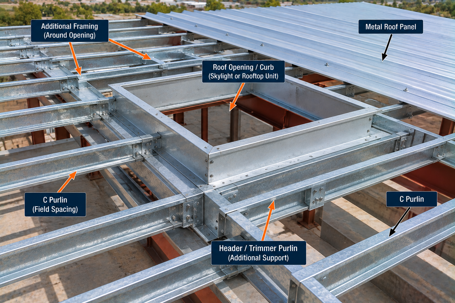
Spacing and layout may need modification around skylights, roof hatches, mechanical units, smoke vents, curbs, and solar equipment. Possible responses include added purlins, headers, subframing, or redistribution members. A single purlin space should not simply be widened around an opening without engineering.
Solar Panels and Added Roof Loads
Existing spacing should not be assumed adequate for new rooftop loads.
ASCE 7-22 contains specific roof-load provisions for solar panels. Solar systems can affect dead load, concentrated attachment loads, wind loading, and roof-panel behavior. Existing purlin spacing should not automatically be assumed adequate for added solar loads without engineering verification of the purlin, panel, and connection capacity.
Steel vs Wood Purlin Spacing
Kept brief since this page owns steel metal-building spacing specifically.
Cold-formed steel purlins are repetitive secondary roof members with spacing related to the metal roof panel spanning between them. Traditional wood purlins can serve a different structural role, such as supporting rafters in a heavier timber framing system, and wood spacing conventions should not be mixed into a steel-purlin spacing chart.
2024 IBC and AISI Requirements
The building-code framework behind cold-formed purlin design.
Section 2204 of the 2024 IBC requires cold-formed carbon and low-alloy structural members to comply with AISI S100, the North American Specification for the Design of Cold-Formed Steel Structural Members. For the 2024 edition I-Codes, AISI identifies AISI S100-16 (2020) with Supplement 2-20 as the adopted specification, though a newer AISI S100-24 edition also exists; always cite the edition actually adopted by the governing jurisdiction.
ASCE 7-22 Roof, Snow, and Wind Loads
The current national loading framework for purlin spacing decisions.
ASCE 7-22 provides the current loading framework for hazards including dead and live loads, snow, rain, wind, seismic, and other loads and combinations. For purlins specifically, the most relevant provisions address roof and live loading, wind pressures including component and cladding effects, snow and drift, rain and ponding, and roof loads at solar panel installations.
MBMA 2024 Purlin Roof-System Guidance
The system-level authority source for purlin spacing decisions.
The Metal Building Manufacturers Association’s 2024 Roof Framing Design Guide provides system-level guidance on purlins, continuous systems, diaphragm behavior, bracing, and anchorage, explicitly treating purlins, roof panels, bracing, and anchorage as an interacting structural system rather than isolated members. This system-level view is the reason a single generic purlin spacing number cannot substitute for a complete engineered check.
How to Read a Roof Panel Load-Span Table
Panel tables typically separate positive (gravity) and negative (uplift) allowable pressures by span.
Identify the exact panel profile and gauge, confirm the support condition (single span, two span, or three or more spans), find the allowable positive pressure at the intended span, find the allowable negative (uplift) pressure at the same span, and confirm that the manufacturer’s connection or fastener capacity does not further reduce the allowable value. The lowest governing number between panel capacity and connection capacity controls.
How to Read a Purlin Load Table
Purlin tables must be read alongside the panel table, not in isolation.
Identify the exact manufacturer section, confirm base thickness and steel grade, confirm span and spacing, confirm simple-span or continuous condition, check gravity capacity, check uplift capacity separately, check deflection, and confirm that the roof-panel restraint assumptions built into the table match the actual roof system being used.
How to Determine Purlin Spacing, Step-by-Step
The correct overall logic for selecting purlin spacing on a real project.
Purlin Spacing Selection Workflow
Common Purlin Spacing Mistakes
Assuming all metal roofs use 4-ft spacing
4 ft is a system example, not a universal figure.
Assuming all metal roofs use 5-ft spacing
5 ft is a valid system-specific limit for some products, not a general rule.
Treating 5 ft 6 in. as a universal maximum
It is a system option under specific conditions.
Confusing purlin spacing with purlin span
Spacing sets tributary load; span sets bending and deflection demand.
Measuring horizontally instead of on slope
Drawings often specify spacing measured along the roof slope.
Ignoring roof-panel allowable span
The panel must itself be rated for the resulting span.
Checking purlin strength but not panel strength
Both must be verified independently.
Checking panel strength but not purlin strength
Panel adequacy does not guarantee purlin adequacy.
Ignoring clip or fastener capacity
Connections can govern before the panel or purlin does.
Ignoring wind uplift
Gravity-adequate spacing does not guarantee uplift adequacy.
Ignoring snow drift
Localized drift loads can exceed field-area assumptions.
Using one field pressure across all roof wind zones
Edge and corner zones typically see higher uplift demand.
Ignoring roof slope
Slope affects on-slope layout and load resolution.
Ignoring simple vs continuous behavior
Continuity changes allowable load at the same spacing.
Assuming Z and C purlins have identical capacity
Symmetry and continuity behavior differ between the two shapes.
Assuming all same-depth purlins are equivalent
Flange, lip, and thickness vary by manufacturer.
Ignoring base steel thickness
Thickness directly affects capacity at a given spacing.
Ignoring roof-panel restraint
Panel type affects the lateral restraint assumed in design.
Assuming standing-seam restrains purlins like through-fastened panels
Clip type changes the restraint provided.
Ignoring deflection
Serviceability can control before strength does.
Ignoring openings and curbs
Repetitive spacing often cannot continue through a penetration.
Adding solar panels without rechecking framing
New loads can exceed the original design assumptions.
Treating manufacturer spacing examples as universal code limits
System values apply only to that specific product and configuration.
Purlin Spacing Chart Limitations
Read before finalizing purlin spacing
No universal purlin spacing applies to all roofs. The 4 ft, 5 ft, and 5 ft 6 in. examples on this page are system examples, not general code limits. Roof-panel allowable span may govern, and purlin structural capacity may govern separately, since span and spacing are separate variables. Wider spacing increases tributary load, snow and wind vary by site, and roof wind pressure varies by zone. C and Z sections behave differently, and thickness and material strength both matter. Continuous and simple systems differ, and roof-panel restraint affects purlin capacity, with standing-seam systems requiring clip and system-specific assumptions. Connections and fasteners can govern, and deflection may control before strength does. Final spacing must follow engineered drawings and the applicable manufacturer and code requirements.
Purlin Spacing FAQs
Download the Purlin Spacing Chart
Get a printable reference including the spacing examples, tributary load conversion, and standards summary on this page for jobsite or office use.