Z Purlin Size Chart – Dimensions, Thickness, Weight & Span Reference

Z Purlin Size Chart
Dimensions, Thickness, Weight & Span Reference
Actual web depth, flange, lip, base steel thickness, and weight per foot for common Z-purlin product lines, cross-checked against current manufacturer data, plus lap, span versus spacing, and AISI/MBMA load-table guidance for U.S. metal roof systems.
 Reviewed by Muhammad Ramzan Babar, PhD Researcher (Plasma Physics) & Calculator Developer, View Profile
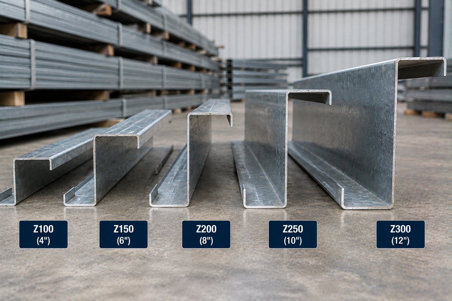
An “8-inch,” “10-inch,” or “12-inch” Z purlin is not a complete specification
Unlike AISC W-shapes, cold-formed Z purlins have no single nationally standardized dimensional series. Current manufacturer lines such as Metal Sales and MBCI publish different flange widths, lip dimensions, gauges, and weights for the same nominal web depth. Always identify the exact manufacturer product and gauge before ordering material or checking a load table.
Z Purlin Size Chart, Quick Reference
The message above this chart matters as much as the chart itself: current manufacturer Z-purlin lines use different flange widths, lips, and thicknesses at the same nominal web depth, so this table is grouped by product family rather than presented as one universal size series.
| Nominal Size | Actual Size (Web x Top Flange x Bottom Flange) | Gauge | Weight per Foot |
|---|---|---|---|
| 4 x 3 | 4 x 2 5/8 x 2 7/8 in. | 16 | 2.15 lb/ft |
| 6 x 3.5 | Actual N/A (equal-leg product) | 14 | ~2.8 lb/ft |
| 8 x 3.5 | 8 x 3 1/8 x 3 3/8 in. | 14 | 3.74 lb/ft |
| 8 x 3.5 | 8 x 3 1/8 x 3 3/8 in. | 12 | 5.58 lb/ft |
| 9 x 3.5 | 9 x 3 1/8 x 3 3/8 in. | 14 | 3.97 lb/ft |
| 10 x 3.5 | 10 x 3 1/8 x 3 3/8 in. | 14 | 4.21 lb/ft |
| 10 x 3.5 | 10 x 3 1/8 x 3 3/8 in. | 12 | 6.28 lb/ft |
| 12 x 3.5 | 12 x 3 1/8 x 3 3/8 in. | 14 | 4.68 lb/ft |
| 12 x 3.5 | 12 x 3 1/8 x 3 3/8 in. | 12 | 6.98 lb/ft |
Dimensions and weights shown are sourced directly from published manufacturer tables (MBCI Cee/Zee product data and Metal Sales Zee product data). “Actual size” for Zee sections often shows unequal flanges even within one nominal family, since the offset allows adjacent sections to nest for lapping. Confirm the exact product and current catalog before ordering.
Common Z Purlin Sizes
Current market products cluster around five general depth classes, though exact combinations of flange width, lip, and gauge vary by manufacturer.
| Depth Class | Typical Nominal Web Depths | Typical Flange Range |
|---|---|---|
| 4-in. class | 3.5 in., 4 in. | 1.5 to 3.5 in. |
| 5/6-in. class | 5 in., 6 in. | 2.5 to 3.5 in. |
| 7/8-in. class | 7 in., 8 in., 9 in. | 2.5 to 3.5 in. |
| 9/10-in. class | 9 in., 10 in. | 2.5 to 3.5 in. |
| 11/12-in. class | 11 in., 12 in. | 2.5 to 3.5 in. |
Metal Sales currently lists Zee web heights of 4, 6, 8, 9, 10, and 12 in. with flange widths of 2.5, 3, 3.5, and 4 in. across 12, 14, and 16 gauge. MBCI’s current Cee/Zee catalog spans roughly 3.5 in. through 12 in. nominal depth across several flange families and 12, 13, 14, and 16 gauge. Depth alone never determines capacity; flange width, lip, thickness, and steel grade all matter.
Z Purlin Thickness Quick Chart
Use the manufacturer’s published base-steel thickness, not an assumed generic gauge conversion.
| Gauge Label | Base Thickness (in.) | Base Thickness (mm) | Common Z Depths Available |
|---|---|---|---|
| 16 ga | 0.0598 | 1.52 | 4 to 12 in. |
| 14 ga | 0.0747 | 1.90 | 3.5 to 12 in. |
| 13 ga | 0.0897 | 2.28 | 8 to 11 in. (product-specific) |
| 12 ga | 0.1046 | 2.66 | 7 to 12 in. |
Metal Sales currently lists 12, 14, and 16 gauge across its Zee range, while MBCI includes 12, 13, 14, and 16 gauge depending on nominal size. Gauge availability at a given depth is manufacturer and product specific.
Equal-Leg vs Lap-Leg Z Purlins
Manufacturer catalogs distinguish several Zee configurations rather than offering one universal Z shape.
| Configuration | Flanges | Main Purpose |
|---|---|---|
| Equal-Leg Zee | Similar/equal flange geometry | Simple/general secondary framing |
| Unequal/Lap-Leg Zee | Offset/unequal flange geometry | Nesting and lapping at supports |
| Sloped Zee | Product-specific geometry | Roof-slope/system-specific use |
Metal Sales currently lists separate equal-leg, lap-leg, and sloped Zee product lines. Choosing the wrong configuration for a continuous or lapped roof system can prevent the sections from nesting correctly at the frame line.
What Is a Z Purlin?
A cold-formed, thin-walled structural steel secondary roof member with a Z-shaped cross-section.
A Z purlin supports metal roof panels, spans between primary rigid frames, rafters, or trusses, transfers gravity and wind-uplift forces down into the primary structure, and works together with roof panels and anchorage as one structural system rather than as an isolated beam. Nucor describes purlins and girts as roll-formed Z or C secondary structural members selected in size and thickness according to design criteria, with either simple-span or continuous behavior.
Why Z Purlins Are Used in Metal Roof Systems
Several practical advantages explain why Z sections dominate pre-engineered metal building roofs.
- Thin-walled material efficiency, delivering strength without the material volume of hot-rolled shapes
- High strength-to-weight ratio for its cold-formed steel cross-section
- Ability to nest and lap at frame lines, unlike most other cold-formed profiles
- Ease of forming continuous multi-span systems across several bays
- Convenient flange geometry for attaching roof panels and clips
- Wide compatibility with pre-engineered metal building systems
The lapping capability is the single most important practical distinction between Z purlins and C purlins, and it is covered in depth later on this page.
Z Purlin vs C Purlin
Both are common cold-formed secondary framing shapes, but they behave differently as a system.
| Feature | Z Purlin | C Purlin |
|---|---|---|
| Cross-section | Z-shaped | C-shaped |
| Nesting for laps | Particularly convenient | Less natural |
| Continuous multi-span systems | Very common | Possible but system-dependent |
| Symmetry | Point symmetry, unsymmetric axes | Singly symmetric |
| Principal axes | Oblique | Different geometric behavior |
| Common roof use | Very common | Common |
| Capacity | Section/system-specific | Section/system-specific |
The 2024 MBMA Roof Framing Design Guide specifically treats cold-formed purlin behavior and continuous purlin design as system-level design issues rather than a simple shape comparison. For C-specific dimensions, see the Steel Channel Size Chart and the broader Roof Purlin Size Chart.
How to Read a Z Purlin Size Designation
Z-purlin naming is manufacturer-specific, unlike AISC’s national W-shape convention.
Designations may communicate nominal web depth, section family, material thickness, and flange/product series, but the exact format differs between manufacturers. A historical Nucor section notation such as “08 Z 075” identified an approximately 8-in. web, Z-section, and 0.075-in. nominal thickness within that particular product system. Do not teach one manufacturer’s designation as a national Z-purlin naming standard.
Read the exact catalog page, not just the size label
A “10-inch Z purlin” from one manufacturer and a “10-inch Z purlin” from another can have different flange widths, lips, and weights even though both use the number “10.”
Nominal Size vs Actual Dimensions
This is one of the most important practical differentiators for Z purlins.
MBCI’s current tables show a nominal 8 x 3.5 in. Zee with actual flanges of approximately 3 1/8 in. and 3 3/8 in., unequal by design so the section nests with another Zee for lapping. The same pattern repeats across MBCI’s 4, 5, 7, 9, 10, 11, and 12-in. nominal Zee families. Never assume both flanges of a nominal size match that nominal number exactly.
| Nominal Size | Actual Web x Top Flange x Bottom Flange |
|---|---|
| 8 x 3.5 | 8 x 3 1/8 x 3 3/8 in. |
| 9 x 3.5 | 9 x 3 1/8 x 3 3/8 in. |
| 10 x 3.5 | 10 x 3 1/8 x 3 3/8 in. |
| 12 x 3.5 | 12 x 3 1/8 x 3 3/8 in. |
Values sourced from MBCI’s current published Cee/Zee product data.
Z Purlin Dimension Anatomy
Every Z-purlin size chart relies on the same set of geometric dimensions.
Web
The vertical overall section dimension, referred to as web depth. This is the “8,” “10,” or “12” in a nominal size label.
Flanges
Horizontal projections on each side of the web. Top and bottom flange widths may be equal or intentionally unequal, depending on the product line.
Lip
The edge stiffener at the end of each flange, which affects local and distortional buckling behavior and factors into section-property calculations.
Thickness
The base steel thickness used for structural calculations, independent of any coating thickness. Additional geometric details include the bend radius at each corner, the flange offset that creates unequal-leg geometry, and any punched web holes for utilities or bridging hardware.
Z Purlin Web Depth Chart
A depth-based lookup across current manufacturer product lines.
| Nominal Web Depth | Metal Sales | MBCI |
|---|---|---|
| 3.5 in. | Not listed | Available |
| 4 in. | Available | Available |
| 5 to 7 in. | Not standard web heights | Available |
| 6 in. | Available | Available |
| 8 in. | Available | Available |
| 9 in. | Available | Available |
| 10 in. | Available | Available |
| 11 in. | Not listed | Available |
| 12 in. | Available | Available |
Depth alone does not determine capacity
Two 8-in. Z purlins can differ in flange width, lip, thickness, steel grade, weight, and section properties. Always confirm the complete specification before comparing sections.
Z Purlin Flange Width Chart
Flange configuration by nominal depth, showing actual top and bottom flange dimensions where published.
| Nominal Depth | Flange Configuration | Actual Top Flange | Actual Bottom Flange |
|---|---|---|---|
| 4 in. | 3 in. family | 2 5/8 in. | 2 7/8 in. |
| 8 in. | 2.5 in. family | 2 1/8 in. | 2 3/8 in. |
| 8 in. | 3.5 in. family | 3 1/8 in. | 3 3/8 in. |
| 10 in. | 3.5 in. family | 3 1/8 in. | 3 3/8 in. |
| 12 in. | 3.5 in. family | 3 1/8 in. | 3 3/8 in. |
Metal Sales currently lists flange widths from roughly 2.5 to 4 in. across its Zee range. MBCI’s tables illustrate why actual Zee flanges intentionally differ. For example, a nominal 3.5-in. flange family may use unequal actual flanges so adjacent members nest during lapping.
Equal-Flange vs Unequal-Flange Z Purlins
A major practical point that a purely nominal size chart can obscure.
Equal-Flange Zee
Top and bottom flanges use similar dimensions. Best suited to general secondary framing that will not be lapped at a support.
Unequal-Flange / Lap-Leg Zee
One flange is slightly narrower than the other so Z sections can nest together when installed with opposite orientation at a frame line.
Key point
An “8 x 3.5 Z purlin” may not literally have two exactly 3.5-in. flanges. Manufacturer geometry controls the actual dimensions.
Z Purlin Lip / Edge-Stiffener Dimensions
The lip is a structural feature, not a decorative detail.
The lip stiffens each flange edge, helps control local buckling, influences distortional buckling behavior, and factors directly into section-property calculations used by AISI design methods. Lip length should be treated as a required field on every primary size row where manufacturer data provides it, not omitted as a minor detail.
Z Purlin Thickness Chart
Base steel thickness is the primary technical value for structural purposes.
| Manufacturer Gauge | Base Thickness (in.) | Base Thickness (mm) | Typical Available Depths |
|---|---|---|---|
| 16 ga | 0.0598 | 1.52 | 4 to 12 in. |
| 14 ga | 0.0747 | 1.90 | 3.5 to 12 in. |
| 13 ga | 0.0897 | 2.28 | 8 to 11 in. |
| 12 ga | 0.1046 | 2.66 | 7 to 12 in. |
Metal Sales currently lists 12, 14, and 16 gauge, while MBCI includes 12, 13, 14, and 16 gauge across its product matrix, with exact gauge offerings differing by nominal size.
Gauge vs Actual Z Purlin Thickness
One of this page’s most important accuracy sections.
Gauge is a market and product designation. Base steel thickness is the engineering dimension used in structural calculations. Coatings increase total coated thickness but not structural base-metal thickness, and product conventions can differ between manufacturers. The 2024 MBMA Metal Building Systems Manual specifically added an appendix addressing steel thickness in inches versus gauge, which reinforces how important this distinction is.
Editorial rule
Always publish the actual base steel thickness alongside any gauge label, since gauge numbering conventions are not perfectly uniform across every product line.
Z Purlin Weight per Foot Chart
Weight scales with depth, flange, and gauge together, not with depth alone.
| Z Section (Nominal) | Gauge | Weight (lb/ft) | Weight (kg/m) |
|---|---|---|---|
| 3.5 x 1.5 | 16 | 1.56 | 2.32 |
| 3.5 x 1.5 | 14 | 1.86 | 2.77 |
| 8 x 3.5 | 14 | 3.74 | 5.57 |
| 8 x 3.5 | 13 | 4.52 | 6.73 |
| 8 x 3.5 | 12 | 5.58 | 8.30 |
| 10 x 3.5 | 14 | 4.21 | 6.27 |
| 10 x 3.5 | 12 | 6.28 | 9.35 |
| 12 x 3.5 | 14 | 4.68 | 6.96 |
| 12 x 3.5 | 12 | 6.98 | 10.39 |
Weight per linear foot is published directly by MBCI for its Cee/Zee product sizes. Weight varies substantially with gauge even at the same nominal depth, useful for estimating, shipping, and erection planning. Heavier does not automatically mean the most appropriate structural section for a given application.
Z Purlin Section Properties
A complete engineering picture requires more than depth and weight.
| Property | What It Represents |
|---|---|
| Gross Area (A) | Total cross-sectional steel area |
| Moment of Inertia (Ix) | Resistance to bending about the strong axis |
| Moment of Inertia (Iy) | Resistance to bending about the weak axis |
| Product of Inertia (Ixy) | Describes the section’s lack of symmetry about conventional axes |
| Section Modulus (Sx) | Relates bending moment to maximum bending stress |
| Torsional Constant (J) | Resistance to twisting |
| Warping Constant (Cw) | Used in torsional-flexural buckling calculations |
| Centroid / Principal-Axis Properties | Locates the section’s geometric center and rotated principal axes |
AISI cold-formed steel references include gross property tables for Z-sections with lips and Z-sections without lips. Do not try to derive complete design capacity from Ix or Sx alone; a full AISI S100-based design check accounts for local buckling, distortional buckling, and lateral-torsional effects that a single section property cannot capture.
What Determines the Required Z Purlin Size?
A Z purlin cannot be sized from web depth or span alone.
Why Z purlins have oblique principal axes
Because a Zee is not symmetric about the conventional web axis, its principal bending axes are rotated relative to the web and flanges. This can introduce biaxial bending components, torsion, and lateral displacement under load, and it is one reason roof-slope orientation affects behavior. Manufacturer and AISI design tables already account for this; a simple Ix-based hand check does not.
Span
Distance between primary frames or supports.
Spacing
Tributary roof width carried by each purlin line.
Section Depth, Geometry, and Base Steel Thickness
Depth, flange width, lip dimension, and thickness together set the section’s structural properties.
Steel Yield Strength
The specified minimum yield strength of the coil steel used to form the section.
Dead Load, Roof Live Load, Snow and Drift, Wind Uplift
Combined gravity and uplift design loads that the purlin and its connections must resist.
Roof Slope, Number of Spans, and Lap Length
Roof geometry and system continuity change how load is distributed along the purlin line.
Roof-Panel Restraint, Bridging/Anchorage, and Deflection Criteria
The complete system, not the isolated purlin shape, ultimately governs the required section.
Z Purlin Span vs Spacing
These two dimensions are frequently confused but are independent variables.
| Term | Definition |
|---|---|
| Span | Distance along the purlin between primary supports |
| Spacing | Distance between adjacent parallel purlins |
Formula
If roof pressure is q (psf) and purlin spacing is S (ft), the line load on the purlin is w = q × S, where w is in lb/ft.
Z Purlin Spacing and Roof-Panel Span
The roof panel itself may limit purlin spacing before the purlin’s own structural capacity does.
| Roof Panel/System | Maximum Panel Span | Purlin Spacing Used | Source/Conditions |
|---|---|---|---|
| Through-fastened panel | Panel manufacturer specific | Set to stay within panel span limit | Panel manufacturer load tables |
| Standing-seam panel | Panel/clip manufacturer specific | Set to stay within panel and clip limits | Panel and clip manufacturer data |
Do not state that Z purlins should be spaced at a fixed distance such as 5 ft universally. See the Metal Roof Panel Span Chart for panel-specific span limits and the Purlin Spacing Chart for spacing selection logic.
Why There Is No Universal Z Purlin Span Chart
This directly addresses a common but incomplete type of competing content.
A simple table pairing Z depth with a single maximum span number is incomplete unless it also specifies the exact section, base thickness, steel strength, purlin spacing, gravity load, wind uplift, single-span versus continuous condition, restraint, and deflection criteria. Because those variables change from project to project, this page teaches readers how to use a manufacturer’s engineered load table correctly instead of publishing one universal span number.
How to Read a Z Purlin Load Table
A practical, step-by-step workflow for using manufacturer load tables correctly.
Load Table Reading Workflow
Single-Span vs Continuous Z Purlins
These two conditions produce different structural behavior and cannot share the same load table.
A single-span Z purlin runs between two supports without continuity over an intermediate support. Simple-span tables cannot automatically be applied to continuous systems, lapped systems, or unequal-span systems, because moment distribution differs in each case. Continuous, lapped systems are the dominant application for Z purlins in metal building roofs, covered in detail next.
Lapped Z Purlin Systems
One of the strongest and most defining sections for this topic.
The 2024 MBMA Roof Framing Design Guide devotes a complete chapter to continuous purlin design, reflecting how important multi-span behavior is in metal-building systems. Continuity involves moment redistribution between end spans and interior spans, with lap regions at interior supports carrying doubled steel locally.
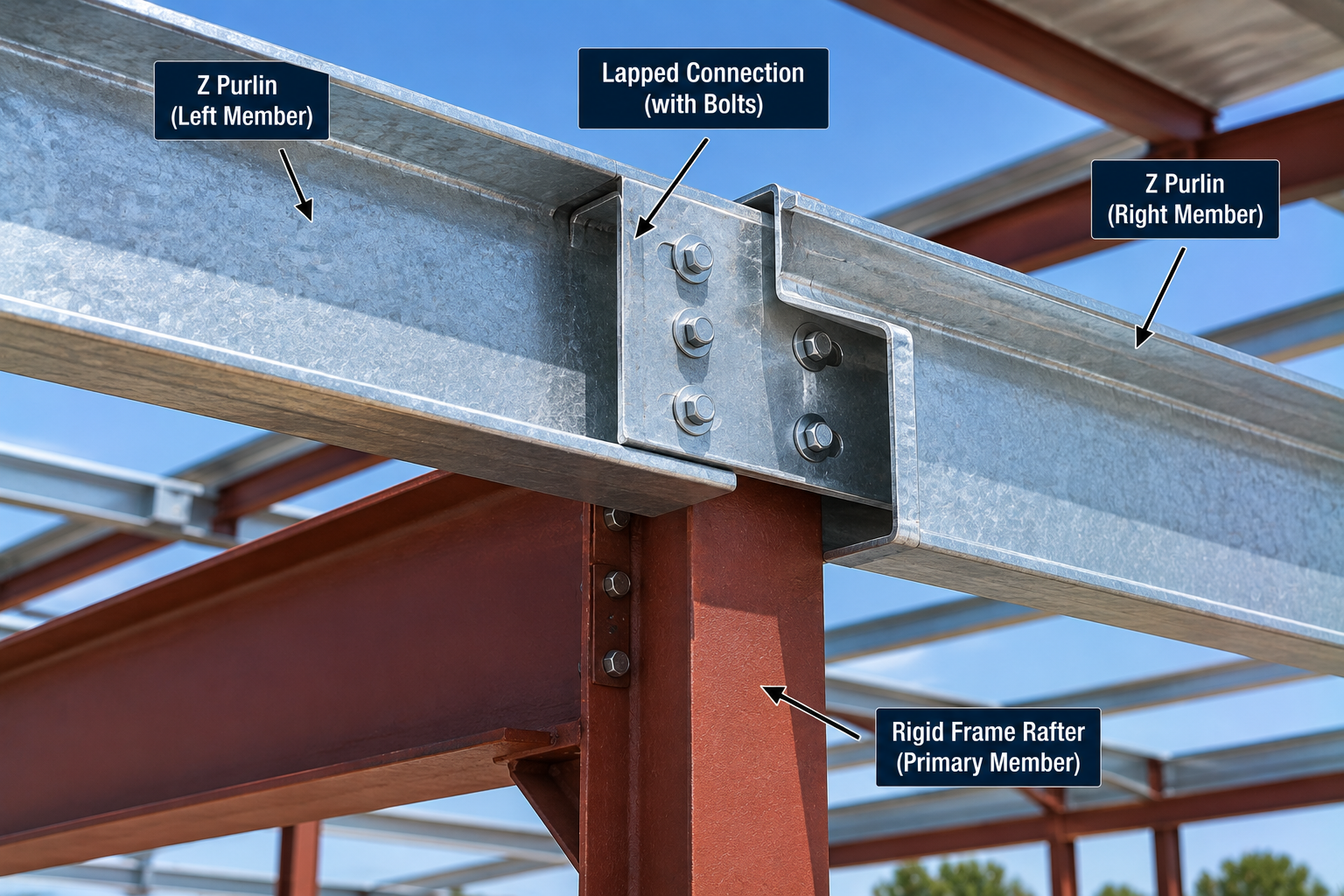
Opposite-oriented Zee sections nest at a frame line, with overlapping webs and flanges bolted together to increase support-region stiffness and create continuity across the purlin line. The 2024 IBC specifically calls for special inspection of installed purlins and girts, including specified lapping, in metal building systems, confirming that laps are engineered structural elements rather than an installation convenience.
Z Purlin Lap Length and Lap Connections
Critical warning: there is no universal “10% of span” or “15% of span” Z-purlin lap rule.
Lap length depends on the engineered system, the exact section, the applied load, the span, the connection design, and the support location. The 2024 MBMA guide deals with forces in and around the purlin lap as part of continuous-system design.
Why Longer Is Not Automatically Better
Connection geometry, bolt pattern, local behavior, and full system analysis all affect whether a given lap length is adequate. Use the engineered lap length from the project drawings or manufacturer load tables, not a fixed percentage rule of thumb.
End Spans, Interior Spans, and Unequal Bays
Continuous load tables often assume equal spans and specific end-span conditions.
Actual buildings may have shorter end bays, variable frame spacing, extensions, or canopies. Do not apply an equal-span continuous load table blindly to a building with unequal spans; the end-span and interior-span behavior in a real continuous table assumes a specific bay pattern that must match the actual structure.
Gravity Load Capacity of Z Purlins
Downward loading combines several distinct load sources.
Gravity loads on a Z purlin include roof panel self-weight, insulation and attached systems, roof live load, snow, and any applicable supported equipment or additional load. Do not rank Z-purlin sections by gravity capacity alone, since the same section can perform very differently once wind uplift is checked, discussed next.
Wind-Uplift Capacity of Z Purlins
An essential and frequently overlooked check.
When wind load reverses the direction of loading, the opposite flange can become the compression flange, restraint conditions change, clip and panel behavior changes, and capacity can differ meaningfully from the gravity-load capacity of the same section. A Z purlin that passes downward loading does not automatically pass wind uplift. ASCE 7-22 is the national load framework for wind and other structural hazards, and the 2024 MBMA manual is aligned with both ASCE 7-22 and the 2024 IBC.
Snow, Drift, and Roof-Slope Effects
Loading provisions that can change the required Z-purlin section even between similar-looking buildings.
ASCE 7-22 Chapter 7 includes provisions for flat-roof snow, sloped-roof snow, partial loading, unbalanced snow, drift, sliding snow, rain-on-snow, and ponding considerations. Two identical buildings with the same bay spacing can require different Z sections because of location and roof geometry alone.
Roof slope also affects Z-purlin behavior because purlin loading resolves relative to the roof plane, the web orientation, and the section’s oblique principal axes discussed earlier. This can introduce lateral force, twist, and a biaxial response even under otherwise simple gravity loading.
Roof Panel Restraint of Z Purlins
One of the most important advanced sections on this page.
Purlin capacity can rely partly on restraint provided by through-fastened roof panels, standing-seam panels, fixed clips, or sliding clips. The 2024 MBMA guide evaluates purlin-panel interaction, diaphragm effects, and anchorage rather than treating a purlin as an isolated beam. The same Z purlin can have different structural behavior under different roof-panel systems, which is why manufacturer load tables state their exact restraint assumptions.
Through-Fastened vs Standing-Seam Roof Systems
Two common roof systems with different restraint characteristics.
| Property | Through-Fastened Roof | Standing Seam |
|---|---|---|
| Panel attachment | Direct fasteners | Clips |
| Thermal movement | More restrained | Designed to accommodate movement |
| Purlin lateral restraint | Often more direct | Clip/system-dependent |
| Uplift behavior | System-specific | System-specific |
| Load tables interchangeable? | No | No |
This comparison explains why generic span charts are risky: the same Z section can carry different loads depending on which roof system provides its lateral restraint.
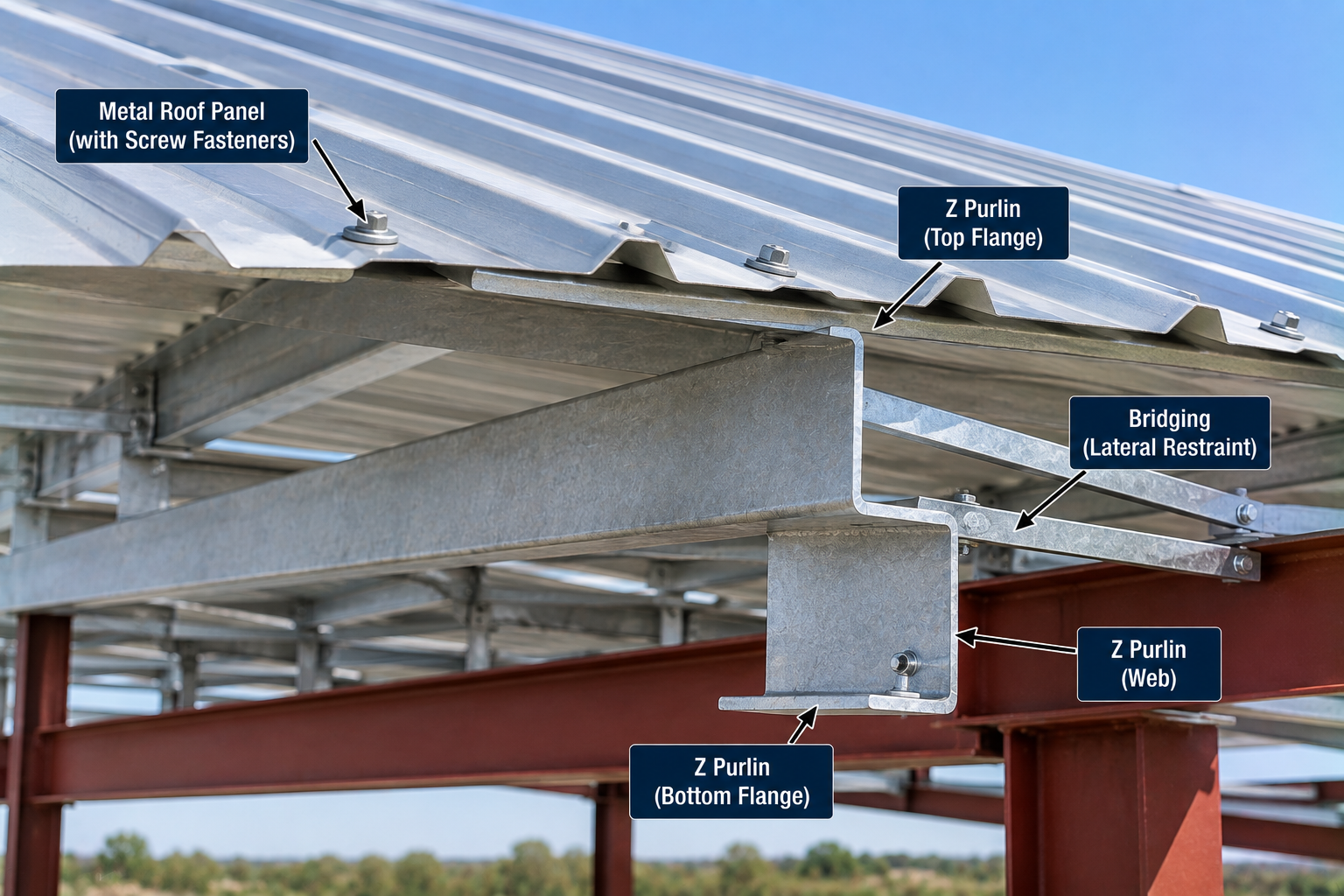
Bridging, Anti-Roll, and Purlin Restraint
Installation-stage and in-service restraint measures that are part of the engineered system.
Purlin bridging, anti-roll bracing, discrete flange restraint, and anchorage all contribute to installation stability and long-term performance. The 2024 IBC’s metal-building inspection requirements include purlin and girt installation and related system requirements. Do not assume the roof panel provides all restraint at every construction stage; bridging is often required before the roof deck is fully attached.
Z Purlin Deflection and Serviceability
Strength and serviceability are separate checks.
Governing effects on deflection can include roof-panel performance, drainage, ponding, visual deflection, brittle interior finishes, and standing-seam clip movement. This page does not prescribe one universal L/180, L/240, or L/360 limit; use the manufacturer, project, or code-required deflection criteria for the specific application.
Z Purlin Materials, Strength, and Finishes
Structural steel and surface protection are separate specifications.
Z purlins are specified by coil steel grade and minimum yield strength (Fy), then finished with red-oxide primer or galvanized coating. Metal Sales currently offers Zee sections in red oxide and galvanized finishes, while MBCI lists red oxide and G90 galvanized options across its product range. Finish or coating and structural base steel thickness are separate specifications; a heavier coating does not add structural capacity.
Additional rooftop systems such as solar panels can also change gravity load, concentrated attachment forces, wind loads, load distribution, and roof-panel or clip behavior. ASCE 7-22 includes specific provisions addressing roof loads at solar panels. Do not add rooftop equipment to an existing purlin system without engineering verification.
AISI, IBC, and MBMA Z Purlin Design Requirements
The code and standards framework governing cold-formed Z-purlin design in the United States.
| Document | Role |
|---|---|
| 2024 IBC, Section 2204 | Requires cold-formed carbon and low-alloy structural members to be designed in accordance with AISI S100 |
| AISI S100-16 (2020) w/S2-20 | The North American cold-formed steel specification edition adopted in the 2024 I-Codes |
| AISI S100-2024 | The newest published AISI S100 edition; confirm which edition the governing jurisdiction has adopted |
| ASCE 7-22 | National load framework for wind, snow, and other structural hazards, aligned with the 2024 IBC and 2024 MBMA manual |
| MBMA 2024 Roof Framing Design Guide (2nd ed.) | System-level guidance on purlin design, continuous purlin design, diaphragm requirements, and anchorage |
For this page, MBMA is the strongest system-level complement to AISI. The MBMA guide covers purlin design methods, continuous purlin design, diaphragm requirements, system anchorage, and miscellaneous roof-framing issues. AISI’s more recent illustrative examples also cover provisions through later supplements, but the edition actually adopted by the governing code or jurisdiction should always take precedence for a specific project.
✓ Verified against 2024 IBC Section 2204, AISI S100, ASCE 7-22, and the 2024 MBMA Roof Framing Design GuideManufacturer Z Purlin Tables and Why They Differ
Metal Sales’ current Zee options include web heights of 4 to 12 in., flange widths of 2.5 to 4 in., 12/14/16 gauge, and equal-leg, lap-leg, and sloped section families. MBCI’s current tables show nominal depths from roughly 3.5 to 12 in., several flange families, unequal actual Zee flanges, 12/13/14/16 gauge depending on size, and published weight per linear foot. This proves the central rule of this page: a “10-inch Z purlin” is a size class, not a complete structural specification.
Z Purlin vs Hot-Rolled Z-Shape or Channel
A Z purlin is thin-wall, cold-formed, lipped, used for metal-building secondary framing, and designed to AISI provisions. A hot-rolled channel is a thicker rolled section using C or MC designation and AISC design methods. Search results often mix cold-formed purlins with structural channels, so this distinction matters. See the Steel Channel Size Chart for hot-rolled channel data.
Z Purlin vs Girt and Eave Strut
A purlin is a roof secondary member. A girt is a wall secondary member. An eave strut sits at the roof-to-wall transition. Nucor identifies purlins and girts as roll-formed Z or C members, while eave struts are generally C-type members.
Common Z Purlin Size Chart Mistakes and Limitations
Selecting a Z purlin from depth alone
Flange width, lip, thickness, and grade all affect capacity.
Assuming every 8-in. or 10-in. Zee is identical
Manufacturer product lines vary significantly at the same nominal depth.
Treating nominal flange dimensions as exact actual sizes
Unequal-leg products intentionally differ from the nominal label.
Using gauge without base metal thickness
Always confirm the published decimal thickness.
Mixing different manufacturers’ dimensions and load tables
Each table applies only to its exact section.
Confusing Z-purlin span with spacing
These are independent variables that both affect design load.
Assuming a fixed spacing such as 4 or 5 ft is universal
Spacing is set by panel span and structural capacity together.
Publishing or trusting a universal span-by-depth chart
Allowable span depends on many variables beyond depth.
Checking gravity load but not wind uplift
The two load directions can govern different failure modes.
Ignoring snow drift or unbalanced snow
ASCE 7-22 provisions can change the required section by location.
Applying a simple-span table to a lapped system
Continuous behavior differs from an isolated simple span.
Assuming a fixed lap-length percentage
Lap length is engineered, not a universal rule of thumb.
Ignoring end-span vs interior-span conditions
Continuous tables assume specific bay patterns.
Assuming roof sheeting always provides full restraint
Restraint depends on the specific panel and clip system.
Treating standing-seam and through-fastened restraint as identical
Their attachment methods provide different lateral restraint.
Ignoring bridging or anti-roll requirements
Bridging is part of the engineered structural system.
Ignoring deflection criteria
Strength and serviceability limits are separate checks.
Treating section modulus alone as capacity
Local and distortional buckling also govern cold-formed sections.
Confusing Z purlins with hot-rolled channels
Different design methods and standards apply to each.
Treating this chart as a substitute for structural design
Final sizing must come from engineered drawings and adopted code.
Chart limitations
Z-purlin dimensions are not nationally uniform across manufacturers. Nominal size can differ from actual flange geometry. Gauge should always be accompanied by actual base steel thickness. Span and spacing are separate variables, and neither alone sets a universal allowable span for a given depth. Gravity and wind-uplift capacity require separate checks, snow and drift loads can govern, and roof slope can affect behavior. Simple-span and continuous/lapped systems behave differently, and lap length is an engineered value rather than a fixed percentage. Roof-panel restraint, bridging, and anchorage are part of the structural system, and standing-seam clip systems require their own design assumptions. Manufacturer load tables apply only to the exact section and stated conditions used to generate them. Final design must comply with the adopted code, AISI S100 provisions, project-specific criteria, and engineered drawings.
Z Purlin Size FAQs
Download the Z Purlin Size Chart
Get a printable reference including the size, thickness, weight, and section-property tables on this page for jobsite or office use.