Welded Wire Reinforcement Size Chart: WWR Sizes & Weight
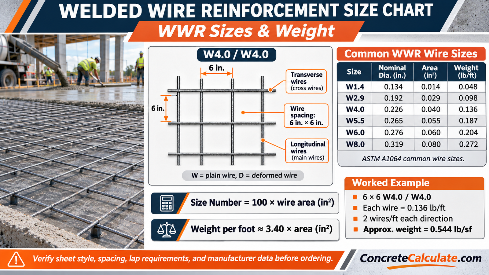
WWR designations, wire diameters, steel area per foot, approximate weights, and practical sizing and placement references.
 Reviewed by Muhammad Ramzan Babar, PhD Researcher (Plasma Physics) & Calculator Developer. View Profile
⭐ Welded Wire Reinforcement Size Chart: Quick Reference
A welded wire reinforcement size chart decodes designations such as 6×6-W2.9×W2.9: 6 in. wire spacing each way, plain W wire of 0.029 in² area (about 0.192 in. diameter), which gives 0.058 in²/ft of steel in each direction and about 42 lb per 100 ft². The W number is area, not diameter.
Common WWR Sizes and Dimensions
| WWR designation | Spacing (in.) | Wire diameter (in.) | Area per wire (in²) | Steel area each direction (in²/ft) | Approx. weight (lb/100 ft²) |
|---|---|---|---|---|---|
| 6×6-W1.4×W1.4 | 6 × 6 | 0.134 | 0.014 | 0.028 | 21 |
| 6×6-W2.0×W2.0 | 6 × 6 | 0.160 | 0.020 | 0.040 | 29 |
| 6×6-W2.9×W2.9 | 6 × 6 | 0.192 | 0.029 | 0.058 | 42 |
| 6×6-W4.0×W4.0 | 6 × 6 | 0.226 | 0.040 | 0.080 | 58 |
| 4×4-W1.4×W1.4 | 4 × 4 | 0.134 | 0.014 | 0.042 | 31 |
| 4×4-W2.0×W2.0 | 4 × 4 | 0.160 | 0.020 | 0.060 | 43 |
| 4×4-W2.9×W2.9 | 4 × 4 | 0.192 | 0.029 | 0.087 | 62 |
| 4×4-W4.0×W4.0 | 4 × 4 | 0.226 | 0.040 | 0.120 | 88 |
Sources: wire diameters and areas from ASTM A1064/A1064M-24 Table 1 (checked in the ASTM A1064/A1064M Table 1 (10e1 edition text)); steel area and approximate weight from WRI TF 202-R-18 Table 4 and WRI TF 206 metric soft conversion (4×4-W2.9 and W4.0). Steel area = wire area × 12 ÷ spacing. This is a selected compilation, not the complete ASTM standard.
✓ Checked against ASTM A1064 Table 1 text and WRI TF 202-R-18 and TF 206 tables, November 2026- W is plain wire; D is deformed wire. The number after it is the nominal wire area in hundredths of a square inch.
- Steel area is per direction and is not the sum of both directions.
- Weights are approximate published product values, not guaranteed shipping weights. Sheet width, length, overhang, and tolerances change delivered quantities. WRI lists W2.0 styles at 29 and 43 lb/100 ft² in one publication and 30 and 44 in another.
- This is a dimensional comparison, not an approved reinforcement design or slab-thickness chart. Confirm style availability with the supplier.
Wire Diameter, Steel Area and Weight
For general mesh applications see the Mesh Reinforcement Chart; this page covers sizes, steel area, and weight.
How to Read the Chart
Reading 6×6-W2.9×W2.9
This identifies the material. It does not show that it suits a particular slab.
What Is Welded Wire Reinforcement?
Welded wire reinforcement (WWR) is a prefabricated grid of plain or deformed carbon-steel wires set at right angles and welded at every intersection, supplied in sheets or rolls.
WWR vs. Welded Wire Fabric
WWR is the current industry name for what was long called welded wire fabric or mesh. ASTM A1064 replaced the older A82, A185, A496, and A497 specifications (WRI TF 202-R-18).
Plain and Deformed Steel Wire
Plain wire develops anchorage at the welded intersections; deformed wire also develops it along the wire through its deformations.
How Welded Wire Mats Are Manufactured
Cold-drawn or deformed wires are fed as longitudinal and transverse wires and resistance welded at their crossings. WWR can be used in structural and nonstructural concrete when properly specified. For fiber alternatives see Fiber Mesh vs. Rebar.
⭐ ASTM A1064 Welded Wire Reinforcement Requirements
ASTM A1064/A1064M-24 covers plain and deformed carbon-steel wire and WWR for concrete, including wire sizes, and sets minimum yield of 65,000 psi for plain and 70,000 psi for deformed WWR.
| Type of WWR | Min. tensile strength (psi) | Min. yield strength (psi) | Weld shear strength (psi × area of larger wire) |
|---|---|---|---|
| Welded plain wire | 75,000 | 65,000 | 35,000 |
| Welded deformed wire | 80,000 | 70,000 | 35,000 |
Source: WRI TF 202-R-18, Table 6 (ASTM and CSA minimum properties). ASTM A1064/A1064M-24 is the active edition; check the edition the project adopts. In WWR the smaller wire must have at least 40% of the area of the larger wire. Wire diameter tolerance is ±0.003 in. up to W5/D5 and ±0.004 in. above, as described in a U.S. government notice quoting A1064. ASTM A1064 alone does not determine a reinforcement design.
✓ Checked against WRI TF 202-R-18 Table 6, November 2026Wire Dimensions and Project Specification Requirements
ASTM says common sizes are in its tables and actual wire sizes are not restricted to those shown. Project documents decide which edition and grade apply. The inch-pound and SI values in ASTM are separate standards and are not exact equivalents.
⭐ How to Read WWR Size Designations
In 6×6-W2.9×W2.9 the first two numbers are longitudinal and transverse spacing in inches, and each W number is the wire area in hundredths of a square inch, so 6×12-W4.0×W2.9 is a different arrangement.
| Designation | Longitudinal spacing | Transverse spacing | Longitudinal wire | Transverse wire |
|---|---|---|---|---|
| 6×6-W2.9×W2.9 | 6 in. | 6 in. | W2.9 (0.029 in²) | W2.9 (0.029 in²) |
| 6×12-W4.0×W2.9 | 6 in. | 12 in. | W4.0 (0.040 in²) | W2.9 (0.029 in²) |
| 6×8-W8×W4 (WRI example) | 6 in. | 8 in. | W8 (0.08 in²) | W4 (0.04 in²) |
| 6×12-W12×W5 (WRI order example) | 6 in. | 12 in. | W12 (0.12 in²) | W5 (0.05 in²) |
Designation convention from WRI TF 202-R-18: first number = longitudinal spacing, second = transverse spacing, then longitudinal and transverse wire size. Confirm orientation on the supplier drawing.
✓ Checked against WRI TF 202-R-18, November 2026Meaning of W and D
W is plain wire and D is deformed wire; D4.0 and W4.0 both have 0.040 in² area.
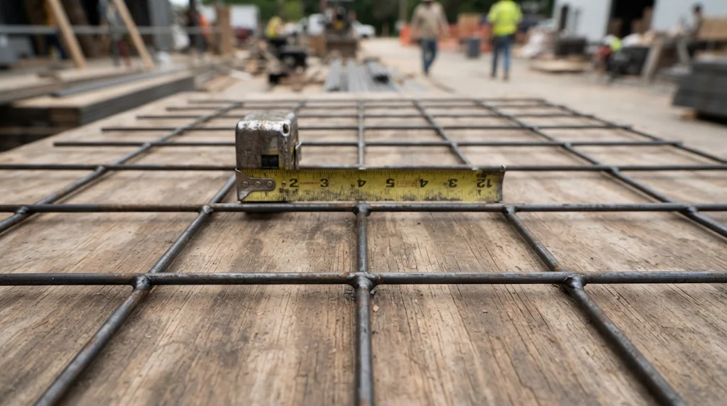
⭐ WWR Wire Size and Diameter Chart
WWR wire sizes run from W1.4 (0.134 in. diameter, 0.014 in²) to W10 (0.357 in., 0.100 in²) in the common range, and the W number gives area, not diameter.
| Wire designation | Area (in²) | Diameter (in.) | Diameter (mm) |
|---|---|---|---|
| W1.4 | 0.014 | 0.134 | 3.39 |
| W2.0 | 0.020 | 0.160 | 4.05 |
| W2.9 | 0.029 | 0.192 | 4.88 |
| W4.0 | 0.040 | 0.226 | 5.73 |
| W5.0 | 0.050 | 0.252 | 6.41 |
| W5.5 | 0.055 | 0.265 | 6.72 |
| W6.0 | 0.060 | 0.276 | 7.02 |
| W8.0 | 0.080 | 0.319 | 8.11 |
| W10.0 | 0.100 | 0.357 | 9.06 |
Source: ASTM A1064/A1064M-24 Table 1, as listed in the ASTM A1064/A1064M Table 1 (10e1 edition text) (diameter in inches; metric diameters as ASTM lists them from exact area). Dividing a rounded inch diameter by 25.4 can differ by about 0.01 mm. These are plain-wire values; deformed wire cannot be fully described by an equal-area circle.
✓ Checked against ASTM A1064 Table 1 text and WRI TF 202-R-18 and TF 206 tables, November 2026Wire area and diameter, W2.9
A W4.0 wire is not 4 mm or 0.4 in.
Larger Wire Sizes
| Wire designation | Area (in²) | Diameter (in.) | Diameter (mm) |
|---|---|---|---|
| W12 | 0.120 | 0.391 | 9.93 |
| W16 | 0.160 | 0.451 | 11.5 |
| W20 | 0.200 | 0.505 | 12.8 |
| W31 | 0.310 | 0.628 | 16.0 |
| W45 | 0.450 | 0.757 | 19.2 |
Source: ASTM A1064/A1064M Table 1 (10e1 edition text), Table 1.
✓ Checked against ASTM A1064 Table 1 text and WRI TF 202-R-18 and TF 206 tables, November 2026Plain W-Wire vs. Deformed D-Wire
Plain W wire (65,000 psi minimum yield) anchors at welded intersections, while deformed D wire (70,000 psi) also anchors along the wire, and both use area-based numbers.
| Property | Plain (W) | Deformed (D) |
|---|---|---|
| Anchorage | At welded intersections | Along the wire by deformations and at intersections |
| Min. yield strength (ASTM A1064) | 65,000 psi | 70,000 psi |
| Designation | W + area in hundredths of in² | D + area in hundredths of in² |
| Example | W4.0 = 0.040 in² | D4.0 = 0.040 in² |
| Selection | By project design | By project design |
Source: WRI TF 202-R-18. Neither type is universally superior; development and splice design follow the governing structural requirements.
✓ Checked against WRI TF 202-R-18, November 2026How to Specify Each Type
Write the prefix and number, such as 4×8-D10×D4, and keep the same type in each direction only if the design requires it.
WWR Wire Gauge Conversion Chart
Legacy gauge names map approximately to W numbers, 6 gauge to W2.9 and 10 gauge to W1.4, but WRI recommends specifying by W or D number because gauges give no area or diameter.
| Steel wire gauge | W-number (modern) | Common style (old designation) |
|---|---|---|
| 10 gauge | W1.4 | 6×6-10×10 |
| 8 gauge | W2.1 (styles often listed as W2.0) | 6×6-8×8 |
| 6 gauge | W2.9 | 6×6-6×6 |
| 4 gauge | W4.0 | 6×6-4×4 |
| 2 gauge | W5.4 (exact size) | 6×6-2×2 |
Source: WRI TF 202-R-18 (4, 6, 8, and 10 gauge equivalents) and WRI-based style tables that note the exact W-number for 8 gauge is W2.1 and for 2 gauge is W5.4. Treat gauge equivalents as historical identifiers; confirm with the supplier and order by W/D number. See also the Wire Gauge Chart.
✓ Checked against WRI TF 202-R-18, November 2026Why Gauge Labels Can Be Misleading
Gauge areas are complicated numbers (2 gauge is 0.054 in²), and publications are not always consistent. Use the area-based designation for modern procurement.
⭐ Welded Wire Reinforcement Spacing Chart
Spacing sets how many wires fall in each foot of width, so 6 in. spacing gives 2 wires per foot and 4 in. gives 3, which changes steel area without changing wire size.
| Spacing (in.) | Wires per foot of width | W2.9 steel area (in²/ft) | W4.0 steel area (in²/ft) |
|---|---|---|---|
| 4 | 3 | 0.087 | 0.120 |
| 6 | 2 | 0.058 | 0.080 |
| 8 | 1.5 | 0.044 | 0.060 |
| 12 | 1 | 0.029 | 0.040 |
Typical longitudinal spacings per WRI TF 202-R-18: 2, 3, 4, 6, 8, 12, 16, 18, and 24 in.; typical transverse spacings are 4, 6, 8, 12, 16, and 18 in. Calculated as 12 ÷ spacing and area × 12 ÷ spacing.
✓ Calculated from verified values, arithmetic checked, November 20264×4, 6×6, 6×12, and 12×12 Spacing
Closer spacing adds steel per foot but is not suitable for every application, and custom spacings are possible for special orders.
⭐ Steel Area per Foot of WWR
Steel area per foot is As = Aw × 12 ÷ s, so 6×6-W2.9×W2.9 provides 0.058 in²/ft and 4×4-W2.9×W2.9 provides 0.087 in²/ft in each direction.
| Wire | 4 in. spacing | 6 in. spacing | 8 in. spacing | 12 in. spacing |
|---|---|---|---|---|
| W1.4 | 0.042 | 0.028 | 0.021 | 0.014 |
| W2.0 | 0.060 | 0.040 | 0.030 | 0.020 |
| W2.9 | 0.087 | 0.058 | 0.044 | 0.029 |
| W4.0 | 0.120 | 0.080 | 0.060 | 0.040 |
Calculated with As = Aw × 12 ÷ s. Areas are per direction, not the sum of both.
✓ Calculated from verified values, arithmetic checked, November 2026Steel area, 6×6-W4.0×W4.0
Compare W2.9 at 6 in. (0.058): 0.080 is about 37.9% more steel, not 37.9% more slab capacity.
What in²/ft Means
Steel cross-section per foot of slab width, reported separately for each wire direction. Percent increase = (As2 – As1) ÷ As1 × 100: (0.080 – 0.058) ÷ 0.058 = 37.9%.
⭐ WWR Weight Chart: Pounds per 100 Square Feet
6×6-W2.9×W2.9 weighs about 42 lb per 100 ft² as published, against 39.4 lb for an ideal continuous grid, because sheet geometry adds wire.
| Mesh style | Published approximate | Theoretical steel-only (continuous grid) |
|---|---|---|
| 6×6-W1.4×W1.4 | 21 | 19.0 |
| 6×6-W2.0×W2.0 | 29 | 27.2 |
| 6×6-W2.9×W2.9 | 42 | 39.4 |
| 6×6-W4.0×W4.0 | 58 | 54.3 |
| 4×4-W1.4×W1.4 | 31 | 28.5 |
| 4×4-W2.0×W2.0 | 43 | 40.8 |
| 4×4-W2.9×W2.9 | 62 | 59.1 |
| 4×4-W4.0×W4.0 | 88 | 81.5 |
Published values from WRI TF 202-R-18 Table 4 and WRI TF 206 metric soft conversion. Theoretical = 2 × (Aw × 12 ÷ s) × 12 in. × 0.283 lb/in³ × 100. WRI uses 3.4 lb per foot per in² of wire (about 12 × 0.283). Published weights include finite sheet geometry, and WRI lists 6×6-W2.0 at 29 or 30 and 4×4-W2.0 at 43 or 44 in different documents.
✓ Checked against ASTM A1064 Table 1 text and WRI TF 202-R-18 and TF 206 tables, November 2026WRI sheet-weight method
This is the WRI procedure from TF 202-R-18. It counts the extra edge wire, so it exceeds a continuous-grid value.
Theoretical weight, 6×6-W2.9×W2.9
Use the published or supplier value for procurement.
Weight per Sheet and Estimating Limitations
For an 8 ft × 20 ft sheet (160 ft²) of 6×6-W2.9×W2.9, the published value gives about 67 lb (0.42 × 160). Actual weight varies with overhangs and rounding. Rebar weights are on the Rebar Weight Chart.
WWR Size Conversion: Inches to Millimeters
WWR metric styles are soft conversions, so 6×6-W2.9×W2.9 is approximately 152×152-MW19×MW19, not an exact dimensional identity.
| U.S. customary WWR style | Approximate metric style | Metric wire area (mm²) | Notes |
|---|---|---|---|
| 6×6-W1.4×W1.4 | 152×152-MW9×MW9 | 9 | Soft conversion; wire area rounded to whole mm² |
| 6×6-W2.9×W2.9 | 152×152-MW19×MW19 | 19 | Common building fabric conversion |
| 6×6-W4.0×W4.0 | 152×152-MW26×MW26 | 26 | Soft conversion; not an exact specification equivalence |
| 4×4-W2.9×W2.9 | 102×102-MW19×MW19 | 19 | Soft conversion; spacing rounded to whole mm |
Source: WRI TF 206 metric soft conversion. WRI instructs users to soft convert U.S. customary styles and round metric spacing and wire area to whole numbers; these are approximate equivalents, not exact substitutes.
✓ Checked against WRI TF 206 table, November 2026Area converts at 645.16 mm² per in², but WRI rounds the metric wire area to whole mm². Do not mix exact U.S. and metric specifications in one order.
Common Welded Wire Reinforcement Sheet Sizes
WWR sheets are commonly 5 to 10 ft wide and 10 to 20 ft long, while rolls are commonly 5 to 7 ft wide and 150 or 200 ft long, but actual stock depends on supplier and region.
| Product form | Reported dimensions | Handling notes | Specification check |
|---|---|---|---|
| Sheets | Common widths 5 to 10 ft | Common lengths 10 to 20 ft; 25 ft common in parts of western U.S. | Actual dimensions and overhangs are supplier-specific |
| Rolls | Common widths 5 to 7 ft | Common lengths 150 or 200 ft | Rolls require unrolling and straightening |
Source: WRI TF 202-R-18. These are common examples, not universal stock dimensions. Custom sizes and minimum order quantities vary by manufacturer.
✓ WRI TF 202-R-18 supplier dimensions checked, November 2026| Property | Required information | Why it matters |
|---|---|---|
| Mesh style | Example: 6×12-W12×W5 | Wire spacing and sizes |
| Product form | Sheet or roll | Handling and placement |
| Sheet width and length | Supplier dimensions | Coverage and layout |
| Overhangs | Side and end details | Actual product geometry |
| Material | Plain or deformed wire | Design compatibility |
| ASTM edition | A1064/A1064M-24 or adopted edition | Product compliance |
| Documentation | Supplier certification | Inspection and approval |
Specification fields based on WRI TF 202-R-18 typical order example and ASTM A1064. Confirm supplier capacity and dimensions.
Welded Wire Reinforcement Rolls vs. Sheets
Sheets arrive flat and are generally easier to place accurately, while rolls need unrolling and straightening and can be harder to hold at the specified elevation.
- Sheets: good placement control; widths and lengths vary. Side overhangs must be specified.
- Rolls: convenient for continuous runs but require straightening and support.
Choose based on the approved design, placement method, and available crew/equipment, not on a universal cost claim.
WWR Sizes for Concrete Slabs on Ground
WWR in slabs-on-ground often controls crack width and helps maintain aggregate interlock, but the wire size and spacing come from the design, not a generic slab thickness.
Shrinkage and Temperature Reinforcement
WWR can help control crack widths in two directions.
Slab Geometry and Joint Spacing
Slab dimensions, joints, loads, and subgrade support all matter.
Design-Specified Steel Area
Compare required As in each direction with the WWR style. See the Mesh Reinforcement Chart for general applications.
Why Slab Thickness Alone Is Insufficient
A 4 in. slab does not automatically prescribe W2.9 or another mesh. Use the approved design.
WWR Sizes for Driveways, Patios and Sidewalks
Driveways, patios, and sidewalks may use WWR for crack control, but loads, joint spacing, support, and subgrade determine the required steel area, not a one-size recommendation.
Do not claim W2.9 or W4.0 suits every 4 in. slab. Link the reader to the Concrete Slab Thickness Chart and the Rebar vs. Wire Mesh comparison, then follow the project plan.
Structural WWR for Walls, Precast and Elevated Slabs
Properly designed WWR can serve as structural reinforcement in walls, precast elements, bridges, and elevated slabs, but it must be detailed and developed for the structural demand.
- Structural WWR may be an alternative to bar arrangements for approved designs.
- Wire area alone does not establish capacity; grade, bond, welds, development, splices, and the design model matter.
- Use the approved drawings and structural engineer’s design; do not derive load capacity from this chart.
⭐ WWR Placement Depth and Concrete Cover
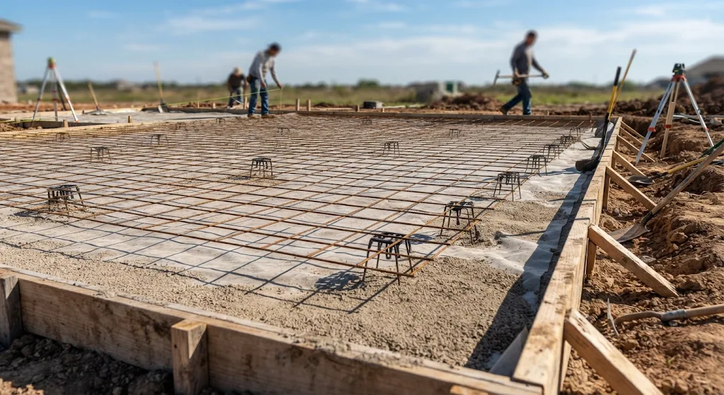
ACI 301-20 requires WWR to be positioned and supported before concrete placement as shown in the contract documents, and ACI 302.1R advises against pulling mesh up through fresh concrete.
| Source | Requirement or recommendation | Application |
|---|---|---|
| ACI 301-20 §3.3.2.5(a) | Place WWR before concrete placement and support as shown in contract documents and CRSI RB4.1 | Contract requirement when specified |
| ACI 301-16 §3.3.2.5 | Support spacing no more than 12 in. for WWR smaller than W4.0 or D4.0 | Edition-specific requirement |
| ACI 302.1R-15 §5.2.4 | Do not place WWR on ground and pull it up, or walk it in after placement | Guidance |
| WRI TF 202-R-18 | Middle third of 4 to 6 in. slab as light construction guidance | Not a universal structural elevation |
Sources: ACI technical FAQ on WWR placement; WRI TF 202-R-18. The placement elevation and cover must match the approved design and project requirements; no single mid-depth location applies to every slab.
✓ ACI FAQ confirms ACI 301 and ACI 302.1R provisions, November 2026For cover requirements see the Concrete Cover Chart.
Support Chairs and Bolsters
Supports must hold the specified elevation under foot traffic and concrete placement.
⭐ WWR Lap Splice and Overlap Requirements
WWR splice length is not one universal overlap, because ACI 318-19 Section 25.5.4 and the project details depend on wire size, spacing, concrete, reinforcement function, and structural requirements.
| Application | Requirement source | What to check |
|---|---|---|
| Structural WWR | ACI 318-19 §25.5.4 and approved design | Wire size, spacing, development, concrete strength, reinforcement function |
| Construction execution | ACI 301-20 and project specifications | Specified overlap, location, support, continuity |
| Light construction crack control | WRI guidance and project details | Do not assume a structural splice length applies |
Sources: ACI 318-19 Section 25.5.4, ACI 301-20, and WRI. No universal overlap length is given here. For rebar lap terminology see the Rebar Lap Splice Chart.
Distinguish structural development and splice provisions from the overlap used to lay sheets for construction.
⭐ How to Calculate WWR Sheet Quantity
For repeated sheets, estimate the count in each direction using sheet dimensions minus assumed overlap, then multiply the counts, with the final layout adjusted for edges and the approved splice detail.
Preliminary count equations: Nx = 1 + ceil(max(0, Lx – Sx) ÷ (Sx – ox)); Ny = 1 + ceil(max(0, Ly – Sy) ÷ (Sy – oy)); sheets = Nx × Ny.
Preliminary sheet count for a 30 ft × 40 ft slab
The 0.5 ft overlap is an arithmetic assumption, not a structural lap recommendation. Layout, sheet orientation, edges, cuts, offcuts, and the approved splice detail change the order quantity.
Use actual product dimensions and the approved overlap from project documents. Do not use the example’s assumed overlap as a structural splice length.
⭐ How to Calculate WWR Material Weight
For 1,000 ft² of 6×6-W2.9×W2.9 mesh, the WRI approximate product weight is 1,000 ÷ 100 × 42 = 420 lb, before extra overlap area and packaging.
For WWR at spacings sL and sT, theoretical weight per area is the sum of the longitudinal and transverse wires: w = 3.4 × (AL ÷ sL + AT ÷ sT) lb/ft² when areas are in in² and spacings in inches.
| WWR style | Published approximate weight (lb/100 ft²) | Theoretical steel-only (lb/100 ft²) |
|---|---|---|
| 6×6-W1.4×W1.4 | 21 | 19.0 |
| 6×6-W2.0×W2.0 | 29 | 27.2 |
| 6×6-W2.9×W2.9 | 42 | 39.4 |
| 6×6-W4.0×W4.0 | 58 | 54.3 |
| 4×4-W2.9×W2.9 | 62 | 59.1 |
| 4×4-W4.0×W4.0 | 88 | 81.5 |
Published values from WRI TF 202-R-18 and WRI TF 206 metric soft conversion. Theoretical calculation uses wire area, spacing, and 0.283 lb/in³ steel unit weight. Published stock weights include finite sheet layout and rounding; use supplier data for procurement.
✓ Checked against ASTM A1064 Table 1 text and WRI TF 202-R-18 and TF 206 tables, November 2026Approximate weight for a 1,000 ft² WWR order
Estimate before packaging, supplier-specific weight, and additional area for overlaps or cutting.
WWR vs. Rebar: Steel Area Comparison
6×6-W4.0 WWR provides 0.080 in²/ft in each direction, while #3 rebar at 12 in. on center provides 0.110 in²/ft in one direction, but equal area does not prove equal structural performance.
| Reinforcement arrangement | Nominal steel area per foot of width |
|---|---|
| 6×6-W2.9×W2.9 | 0.058 in²/ft each direction |
| 6×6-W4.0×W4.0 | 0.080 in²/ft each direction |
| 4×4-W4.0×W4.0 | 0.120 in²/ft each direction |
| #3 rebar at 12 in. on center | 0.110 in²/ft |
| #4 rebar at 12 in. on center | 0.200 in²/ft |
WWR values calculated from wire area and spacing; rebar area values per the Caltrans reinforcing bar chart. This compares geometric steel quantity only, not structural equivalence.
✓ Calculated from verified values, arithmetic checked, November 2026Differences in Placement and Development
WWR and rebar differ in bond, welds, development, splice, grade, and placement. Substitution needs engineering approval. See the Rebar Size Chart, Rebar Area Chart, and Rebar vs. Wire Mesh.
Welded Wire Reinforcement Size FAQs
These are the most common questions about welded wire reinforcement size, steel area, and weight.
What does W2.9 mean?
W2.9 identifies plain wire with nominal cross-sectional area 0.029 in². The ASTM nominal diameter is 0.192 in. (4.88 mm), but the number is the area in hundredths of a square inch, not the diameter or a 2.9 mm wire. For deformed wire the equivalent is D2.9.
What does 6×6-W2.9×W2.9 mean?
It means plain W2.9 wires are spaced 6 in. center-to-center in both directions. Each wire has 0.029 in² nominal area, and the mesh provides 0.058 in²/ft steel area in each direction. It is commonly listed at about 42 lb per 100 ft².
What is the diameter of W4.0 wire?
A W4.0 plain wire has nominal area 0.040 in² and nominal diameter 0.226 in. (5.73 mm) under ASTM A1064/A1064M. A deformed D4.0 wire has the same nominal area but ribs, so a circular diameter does not fully describe its shape.
What is the difference between W and D wire?
W means plain or smooth wire; D means deformed wire with ribs. Both use the number to indicate nominal area in hundredths of a square inch. Plain wire develops anchorage at welded intersections, while deformed wire also develops bond along the wire.
Is WWR the same as welded wire mesh?
In construction, WWR means welded wire reinforcement, historically called welded wire fabric or mesh. The reinforced concrete product is made from plain or deformed steel wires welded in a grid. It is not chain-link fencing or general-purpose galvanized utility mesh.
What is the difference between 4×4 and 6×6 mesh?
The numbers describe center-to-center wire spacing in the two directions. At the same W4.0 wire size, 4×4 mesh provides 0.120 in²/ft each direction, while 6×6 provides 0.080 in²/ft. The closer spacing increases steel quantity but does not alone determine suitability.
How many wires are there per linear foot?
The theoretical count is 12 divided by spacing in inches: two wires per foot at 6 in. spacing, three at 4 in., and one at 12 in. Sheet edges and overhangs can change the actual count. WRI counts actual wires when estimating sheet weight.
What is the steel area of 6×6-W2.9×W2.9?
The steel area is 0.058 in²/ft in each direction, calculated as 0.029 in² per wire times 12 ÷ 6 in. spacing. It is not the combined total of the longitudinal and transverse steel, and the value is not a structural design check by itself.
How much does W2.9 mesh weigh?
WRI lists 6×6-W2.9×W2.9 at about 42 lb per 100 ft² and 4×4-W2.9×W2.9 at about 62 lb per 100 ft². The continuous-grid steel-only calculations are lower because finite sheets add edge wires and actual product geometry. Use supplier data for shipping weight.
What are standard WWR sheet sizes?
There is no universal sheet size. WRI reports common sheets about 5 to 10 ft wide and 10 to 20 ft long, with 25 ft sheets common in parts of the western U.S. Rolls are commonly 5 to 7 ft wide and 150 or 200 ft long. Suppliers vary.
Are WWR rolls and sheets interchangeable?
Not automatically. Rolls need unrolling and straightening and can be harder to support at the specified elevation, while sheets arrive flat and are easier to place accurately. Choose the product form and dimensions shown in the project documents and available from the supplier.
Is 6-gauge mesh the same as W2.9?
In common U.S. terminology, 6-gauge plain mesh is often associated with W2.9, but older gauge conversions are inconsistent. Specify by W/D area and complete spacing designation, such as 6×6-W2.9×W2.9, and verify the wire size printed on the supplier product documentation.
Can welded wire reinforcement replace rebar?
It can in some structural applications when properly designed, specified, and detailed. It is incorrect to say WWR can never replace rebar, but equal steel area alone does not establish equivalence because grade, bond, development, splices, orientation, and constructability also matter.
What WWR size is used for a 4-inch slab?
There is no universal WWR size for every 4 in. slab. WRI gives historical light-construction examples based on slab dimensions and joints, but project design, loads, subgrade, concrete, and joints govern. Follow the approved drawings rather than choosing solely from thickness.
Does welded wire reinforcement prevent all cracks?
No. WWR helps control crack width and keep cracked sections together, but it cannot guarantee crack-free concrete. Shrinkage, temperature changes, subgrade movement, joints, concrete quality, curing, and workmanship all influence cracking. Proper joints and subgrade preparation remain important parts of a slab design.
Where should WWR be positioned in a slab?
At the elevation shown on the approved drawings and supported before concrete placement. ACI 301-20 requires WWR to be positioned and supported per contract documents, and ACI 302.1R advises against laying it on the ground and pulling it up during placement.
How much should welded wire reinforcement overlap?
There is no universal overlap. Structural WWR splices follow ACI 318-19 Section 25.5.4 and project details; construction overlap for sheet placement is a separate question. Do not use a rule such as one opening plus 2 in. for every structural splice.
What is ASTM A1064?
ASTM A1064/A1064M is the specification for plain and deformed carbon-steel wire and welded wire reinforcement for concrete. It covers material, dimensional, and mechanical properties. Check the adopted project edition; the outline references the 2024 version, ASTM A1064/A1064M-24. It superseded earlier separate standards for plain wire, deformed wire, and welded wire.
How do I convert WWR sizes to metric?
Convert inch spacing by 25.4 and area by 645.16, but WRI uses soft metric styles rounded to whole millimeters and square millimeters. For example 6×6-W2.9×W2.9 is approximately 152×152-MW19×MW19, not an exact product identity. Confirm the metric specification with the supplier.
How do I calculate the number of WWR sheets needed?
Lay out sheet coverage in both directions, subtract the overlap from the repeat dimension, and account for edges, cuts, and reuse of offcuts. The simple count is a planning estimate; the approved splice detail determines structural overlap, and the supplier sheet dimensions control the order.
How to Specify and Order WWR Correctly
A WWR order should name the full style, quantity, product form, sheet size, overhangs, wire type, ASTM edition, and required supplier documentation.
- Designation: for example 6×12-W12×W5, longitudinal then transverse.
- Quantity and form: sheets or rolls.
- Width, length, and overhangs: overall dimensions include overhangs.
- Material: plain W or deformed D, as specified.
- Standard: ASTM A1064/A1064M edition in the contract.
- Documentation: supplier certification and approved drawings.
Example order description
500 sheets, 6×6-W2.9×W2.9, 96 in. overall width, 20 ft length, end overhangs per approved drawing, ASTM A1064/A1064M-24, mill certification required. Confirm the order details with the supplier before purchasing.
⭐ Common WWR Sizing and Installation Mistakes
The most common WWR mistakes are treating the W number as a diameter, using unsupported placement, and choosing a mesh style from slab thickness alone.
Designation and dimensions
- Confusing wire area with diameter
- Using gauge alone instead of W/D designation
- Incorrect spacing or wire orientation
- Assuming 6×6 means a 6 in. clear opening
Weight and quantity
- Treating theoretical weight as guaranteed shipping weight
- Ignoring overhangs and finite sheet geometry
- Using gross sheet area without layout and overlaps
Placement and design
- Unsupported reinforcement or pulling mesh up during placement
- Assuming WWR always belongs at mid-depth
- Using one WWR style for every slab thickness
- Substituting WWR for rebar without engineering approval
- Inventing a universal lap length
- Assuming mesh prevents all cracks
Specification and procurement
- Confusing ASTM metric soft conversion with exact interchange
- Failing to confirm stock availability and ASTM edition
- Ignoring broken welds or damaged wires
⭐ How to Choose the Correct WWR Size
Choose WWR by reading the approved design, identifying the required steel area in each direction, matching wire size and spacing, confirming availability, and checking placement and splice requirements.
- Read the approved drawings and specifications.
- Identify required steel area in each direction.
- Match the W/D wire size and spacing.
- Confirm product form, sheet dimensions, and availability with the supplier.
- Check grade, laps, cover, supports, and placement details.
- Obtain engineer approval for any substitution.
This chart is a dimensional and estimating aid, not an unsupervised structural-design calculator.
Using the Welded Wire Reinforcement Size Chart
This welded wire reinforcement size chart gives WWR wire diameter, steel area per foot, and approximate product weight for common styles.
Read the complete W/D designation, use the steel area in each direction, and treat published weights as estimates. Selection, placement elevation, cover, and splice length must come from the approved design and project documents. For broader mesh applications use the Mesh Reinforcement Chart; for bar sizing and lap design see the Rebar Size Chart and Rebar Lap Splice Chart.
📄 Download WWR Size Chart PDF
Use your browser print function to save this page as a print-ready PDF for estimating and placement folders. Buttons and image placeholders are hidden when printing.
- Wire diameter and steel area chart
- WWR weight references
- Metric soft-conversion examples
- Quantity and weight formulas
- Placement and inspection checklist