Concrete Slump Chart – Ranges, ASTM Test & Interpretation
Concrete Slump Chart
Ranges, ASTM Test & Interpretation
The complete slump reference: consistency ranges in inches and millimeters, the ASTM C143/C143M test procedure, slump by application, and how to interpret and troubleshoot results.
 Reviewed by Muhammad Ramzan Babar, PhD Researcher (Plasma Physics) & Calculator Developer, View Profile
Slump is a consistency measurement, not a strength or workability test
ASTM C143/C143M measures the consistency of fresh concrete only. It is not a direct measurement of compressive strength, water to cementitious materials ratio, or overall workability. NRMCA guidance recommends selecting slump based on placement and finishing requirements rather than an arbitrary universal target.
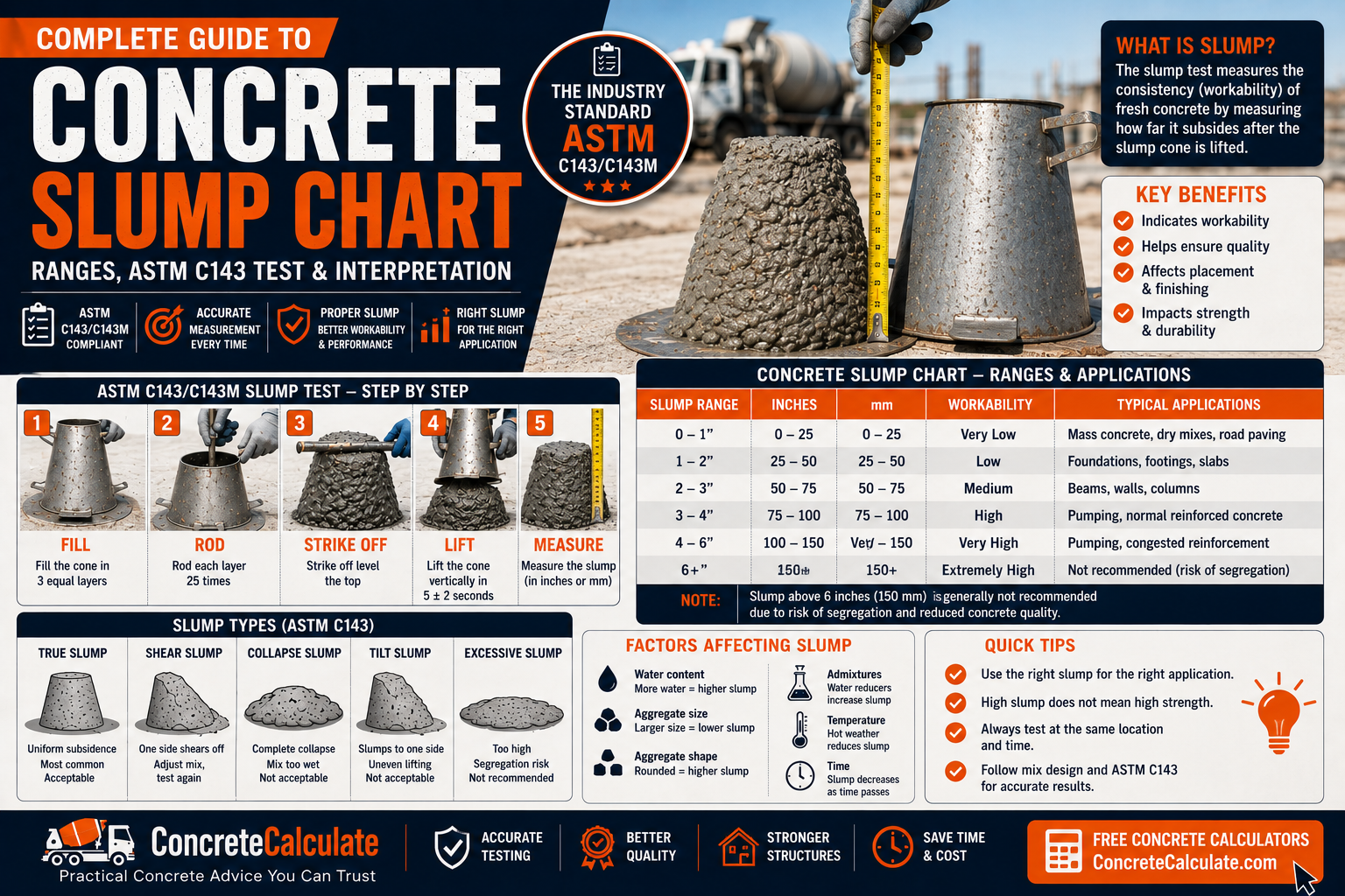
Concrete Slump Chart, Quick Reference
This table shows general descriptive ranges for slump, not universal construction recommendations. The correct slump for any project comes from the mixture design, placement method, and project specifications.
| Slump (in.) | Slump (mm) | General Consistency | General Workability | Typical Context | Interpretation |
|---|---|---|---|---|---|
| 0 to 1 | 0 to 25 | Very stiff | Low | Slipform paving, some precast | May be below ASTM’s plasticity threshold near 1/2 in.; requires mechanical consolidation |
| 1 to 2 | 25 to 50 | Stiff | Low to moderate | Some pavement, low-slump structural mixes | Needs thorough vibration for proper consolidation |
| 2 to 4 | 50 to 100 | Moderate | Moderate | General flatwork, footings, foundations | Common reference range; still depends on mixture and specification |
| 4 to 6 | 100 to 150 | Moderately fluid | Moderate to high | Pumped concrete, congested reinforcement | Often achieved with water-reducing admixtures rather than added water |
| 6 to 9 | 150 to 230 | Fluid | High | Heavily reinforced sections, difficult placement | Approaches ASTM’s upper cohesion limit near 9 in.; verify mixture design |
| Above 9 (not by C143) | Above 230 | Self-consolidating range | Very high | Self-consolidating concrete (SCC) | Measured by slump flow (ASTM C1611), not conventional slump |
Six distinctions this chart depends on
Minimum workable consistency, maximum cohesive limit, design-required slump, typical field slump, and the reference ranges above are all separate concepts. Always check your project’s specified or target slump rather than assuming a range from this table applies directly.
Planning your next concrete project?
Plan concrete materials and project costs with our downloadable Excel estimator pack. For estimating only; follow applicable technical standards for design and installation.
One-time purchase · Digital downloadWhat Is Concrete Slump?
Slump is a standardized measurement of the consistency of fresh, plastic concrete, used for field quality control and laboratory mixture evaluation.
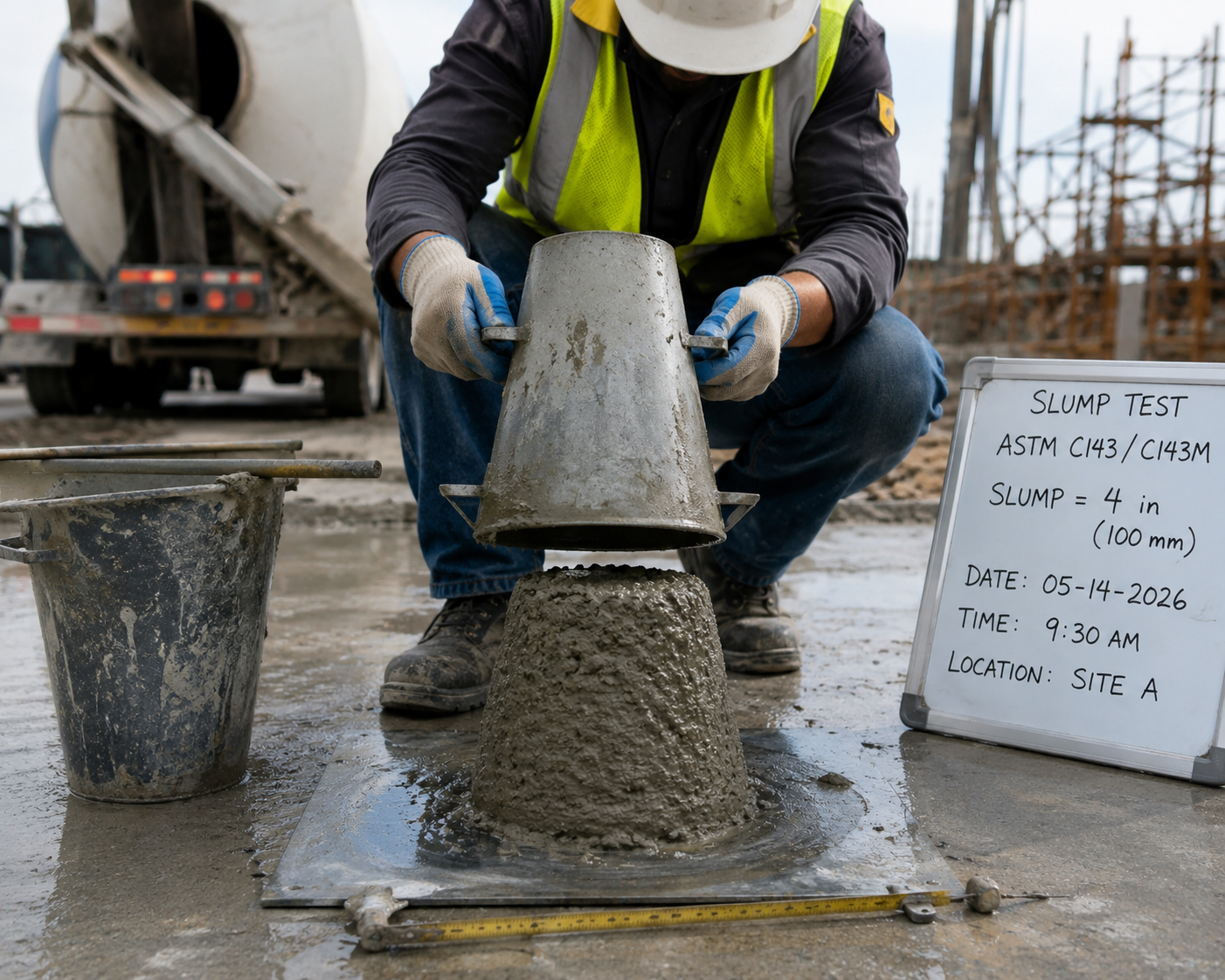
ASTM C143/C143M defines the slump test as a method for determining the consistency of hydraulic cement concrete, applicable both in the laboratory and in the field. A sample of freshly mixed concrete is placed and compacted by rodding in a cone-shaped mold. The mold is then lifted, and the concrete is allowed to subside. The vertical distance between the original mold height and the displaced center of the top surface is measured and reported as the slump.
| Application | Purpose |
|---|---|
| Field quality control | Verify batch to batch consistency at the point of delivery or placement |
| Laboratory evaluation | Evaluate mixture consistency during trial batching and mix design |
Concrete Slump vs Workability
Slump alone does not fully characterize workability. Workability includes placeability, consolidation, finishability, cohesion, and pumpability, not just vertical deformation.
| Property | What Slump Tells You |
|---|---|
| Consistency | Directly measured by slump |
| Placeability | Only partially indicated; depends on placement method and equipment |
| Finishability | Not directly measured; depends on mixture proportions and air content |
| Pumpability | Not fully characterized; rheological properties beyond slump matter |
FHWA’s position on slump and workability
FHWA research on portland cement concrete rheology notes that slump or slump spread alone does not address all aspects of workability, and that other rheological properties can be important for pumpability and placeability, especially for high-workability mixtures.
Concrete Slump Ranges and What They Mean
These are general descriptive categories for communication purposes, not universal code requirements or targets.
| Category | Approximate Range | General Meaning |
|---|---|---|
| Very low slump | 0 to 1 in. (0 to 25 mm) | Very stiff mixture, requires mechanical consolidation |
| Low slump | 1 to 2 in. (25 to 50 mm) | Stiff mixture, limited flow, needs vibration |
| Moderate slump | 2 to 4 in. (50 to 100 mm) | Common general purpose consistency range |
| High slump | 4 to 6 in. (100 to 150 mm) | More flowable, often for pumping or congested reinforcement |
| Very high slump | 6 to 9 in. (150 to 230 mm) | Highly flowable, approaching ASTM’s upper cohesion limit |
Concrete Slump Chart in Inches and Millimeters
ASTM treats inch-pound and SI units as separate standards. Do not mix values between systems when checking conformance.
| Slump (in.) | Slump (mm) | General Description |
|---|---|---|
| 0.5 | 13 | Approaches ASTM’s lower plasticity threshold |
| 1 | 25 | Very stiff |
| 2 | 50 | Stiff to moderate |
| 3 | 76 | Moderate |
| 4 | 102 | Moderate to high |
| 5 | 127 | High |
| 6 | 152 | High |
| 7 | 178 | Very high |
| 8 | 203 | Very high |
| 9 | 229 | Approaches ASTM’s upper cohesion limit |
Conversions rounded to the nearest whole millimeter using 1 in. equals 25.4 mm. ASTM’s own text references 1/2 in. as approximately 15 mm and 9 in. as approximately 230 mm, consistent with standard ASTM rounding conventions for this test method.
How to Read a Concrete Slump Chart
Follow a short verification sequence rather than matching a single number to a single label.
If the measured slump falls outside the tolerance for the specified value, determine whether further investigation, mixture adjustment, or rejection of the batch is warranted under the governing specification.
Concrete Slump by Construction Application
There is no single universally correct slump for any application. The right value depends on the mixture and placement requirements for that specific project.
| Application | Key Consideration |
|---|---|
| Slabs, driveways, sidewalks, patios | Placement, screeding, and finishing needs govern slump selection |
| Footings and foundations | Consolidation around reinforcement and formwork geometry |
| Walls | Formwork height, consolidation method, and reinforcement density |
| Beams and columns | Often more heavily reinforced, may need higher flowability |
| Pavements | Governed by transportation agency specifications, may differ from building concrete |
| Pumped concrete | Pumpability considerations beyond slump alone |
| Heavily reinforced concrete | Higher flowability often needed for full consolidation |
NRMCA’s current recommendation
NRMCA guidance for improving ready mixed concrete specifications recommends allowing the contractor and concrete supplier to select slump based on placement and finishing needs, rather than the specifier imposing an arbitrary fixed target that may not suit the actual placement method.
Concrete Slump for Slabs, Driveways and Flatwork
Flatwork slump selection should reflect placement method, screeding equipment, and finishing schedule rather than a fixed number.
NRMCA’s guidance on finishing concrete flatwork notes that vibrating screeds should not be used with concrete slump exceeding about 3 in. (75 mm), which illustrates why equipment and placement method directly influence the appropriate slump range for a given flatwork project. Weather, time available for finishing, and surface quality requirements also factor into the decision, which should ultimately be resolved through project specifications and coordination with the concrete supplier.

Concrete Slump for Pumped and Structural Concrete
Higher slump is not automatically better concrete. Pumpability and consolidation around congested reinforcement drive slump needs, often addressed through admixtures rather than added water.
| Factor | Relevance |
|---|---|
| Pumpability | Adequate flow through the pump line without segregation or blockage |
| Reinforcement congestion | Higher flowability aids consolidation in tight bar spacing |
| Placement distance | Longer pump lines may need workability-retaining admixtures |
| Admixtures | Water reducers achieve flowability without raising the water content |
Factors That Affect Concrete Slump
Many variables influence measured slump beyond water content alone.
| Factor | Effect on Slump |
|---|---|
| Water content / w/cm | Higher water content generally increases slump, but also affects strength and durability |
| Aggregate size, grading, shape, texture | Rounder, well-graded aggregate improves flow; angular or poorly graded aggregate reduces it |
| Paste volume and cementitious materials | More paste generally improves flowability |
| Air content | Entrained air can slightly affect measured consistency |
| Chemical admixtures | Water reducers and superplasticizers can raise slump without added water |
| Temperature | Higher temperatures generally accelerate slump loss |
| Time since batching | Slump decreases progressively as hydration and moisture loss proceed |
| Aggregate moisture | Surface moisture on aggregate affects the effective water content of the batch |
Concrete Slump and Water-Cementitious Materials Ratio
Slump should not be treated as a direct measurement of w/cm. It is a consistency reading influenced by many factors beyond water content alone.
Common misconception this chart corrects
NRMCA guidance explicitly recommends using water to cementitious materials ratio terminology and warns against treating slump as a measure of water content. Under laboratory conditions with strict material control, slump often correlates with water content, but ASTM itself notes this relationship is not clearly or consistently shown under field conditions.
Two mixtures with the same measured slump can have different w/cm values if one uses a water-reducing admixture instead of added water. For w/cm reference values and their relationship to strength and durability, see the Water-Cement Ratio Chart.
Concrete Slump and Chemical Admixtures
A mixture can achieve higher slump through admixtures rather than added water, which avoids increasing the water to cementitious materials ratio.
| Admixture Type | Effect on Slump |
|---|---|
| Water reducers | Increase slump at a given water content |
| High-range water reducers | Substantially increase slump/flowability without added water |
| Retarding admixtures | Slow hydration, helping maintain slump longer |
| Air-entraining admixtures | Can slightly affect measured consistency |
NRMCA notes that ASTM C94 permits certain adjustments using water-reducing admixtures to increase slump at the jobsite, as an alternative to adding water, provided the adjustment stays within the approved mixture limits.
Does Higher Slump Mean Weaker Concrete?
Not necessarily. The answer depends entirely on how the higher slump was achieved.
| How Higher Slump Was Achieved | Likely Strength Effect |
|---|---|
| Added water beyond mix design | Increases w/cm, likely reduces strength and durability |
| Water-reducing admixture | Slump increases without raising w/cm; strength largely unaffected |
| Original mixture design target | Strength reflects the as-designed mixture proportions |
ASTM specifically cautions that under laboratory conditions slump is generally found to increase with water content and relate inversely to strength, but under field conditions this relationship is not clearly and consistently shown, so care should be taken relating field slump results to strength. For strength reference values, see the Concrete PSI Chart.
Does Adding Water Increase Concrete Slump?
Yes, but it also raises the water to cementitious materials ratio, and any addition must stay within approved mixture limits and be documented.
| Step | Requirement (per ASTM C94 / NRMCA CIP 26) |
|---|---|
| 1 | Establish the maximum allowable slump and mixing water content for the load |
| 2 | Measure slump from a preliminary sample discharged from the truck |
| 3 | Add water or water-reducing admixture to reach the required slump within limits |
| 4 | Measure and record the amount added |
| 5 | Mix for at least 30 revolutions of the drum at mixing speed |
| 6 | Do not add water once the maximum w/cm or maximum slump is reached |
Do not simply avoid all water addition as a blanket rule. ASTM C94 permits controlled jobsite water addition when the slump is below the specified value and the addition does not exceed the maximum water content in the approved mix design. All additions must be measured and documented on the delivery ticket.
Concrete Slump Loss Over Time
Slump loss is the reduction in slump between original batching and the point of discharge or placement.
| Contributing Factor | Mechanism |
|---|---|
| Hydration | Ongoing cement hydration consumes free water over time |
| Temperature | Higher temperatures accelerate hydration and moisture loss |
| Waiting/delivery time | Longer elapsed time generally increases slump loss |
| Admixture effects | Retarders and slump-retaining admixtures can slow slump loss |
NRMCA maintains a dedicated technical resource on slump loss during delivery, defining it as the reduction in slump from original batching to the point of discharge from the truck mixer or other delivery vehicle. Recognizing this pattern helps explain why measured slump at the jobsite can differ from the slump at batching.
Concrete Slump and Temperature
Temperature affects slump retention, setting time, and water demand, without a single universal numerical correction.
| Condition | General Effect |
|---|---|
| Hot weather | Faster slump loss, accelerated setting, higher water demand |
| Cold weather | Slower hydration, slump retained longer, extended setting time |
NRMCA’s hot weather concreting guidance addresses mixture modifications to manage the rate of slump loss and setting time in elevated temperatures. Always verify placement-specific temperature guidance through project specifications rather than applying a fixed numerical adjustment.
Concrete Slump Test, ASTM C143/C143M
ASTM C143/C143M is the governing U.S. standard for the slump test. The current edition is ASTM C143/C143M-26a; confirm the edition referenced by your specifications.
| Scope Item | Requirement |
|---|---|
| Applicable concrete | Plastic (fresh) hydraulic cement concrete |
| Maximum aggregate size | Up to 1.5 in. (37.5 mm); larger aggregate requires wet sieving per ASTM C172/C172M |
| Applicability limits | Not applicable to non-plastic, non-cohesive concrete |
| Lower significance limit | Slumps below about 1/2 in. (15 mm) may not be adequately plastic |
| Upper significance limit | Slumps above about 9 in. (230 mm) may not be adequately cohesive |
| Units | SI and inch-pound units are separate standards; do not combine values |
The procedure is not frozen in time
ASTM periodically revises this test method; the current listing is C143/C143M-26a, and ASTM has an active work item considering further revisions. Always identify which edition your project specifications reference rather than assuming the procedure is fixed indefinitely.
Concrete Slump Test Equipment
The test requires a small, standardized set of tools, each with specific dimensional tolerances under ASTM C143/C143M.
| Equipment | Function |
|---|---|
| Slump cone (mold) | 4 in. top, 8 in. base, 12 in. height frustum, holds the concrete sample |
| Base plate | Rigid, non-absorbent surface for the mold during filling and lifting |
| Tamping rod | Standard rod used to rod each of the three fill layers |
| Measuring device | At least 12 in. long, graduated in increments of at least 1/4 in. |
Equipment for Your Project
Affiliate disclosure: As an Amazon Associate, ConcreteCalculate earns from qualifying purchases. We may also earn a commission from other affiliate links at no additional cost to you.
How to Perform a Concrete Slump Test
The procedure follows a fixed sequence, completed within 2.5 minutes total per ASTM C143/C143M.
Each layer should fill about one third of the mold’s volume, and the entire test, from the start of filling to the final measurement, must be completed within 2.5 minutes to obtain a valid result.
How to Measure Concrete Slump
Slump is the vertical distance between the original mold height and the displaced center of the top surface of the concrete after the mold is removed.
The measurement point is the displaced original center of the concrete sample, not the highest remaining point. Results are recorded to the nearest 1/4 in. and reported in whichever unit system, inch-pound or SI, matches the applicable specification.
True, Shear and Collapse Slump
The way a concrete sample deforms after mold removal can affect whether the measured result has meaning.
| Slump Type | Visual Result | Interpretation |
|---|---|---|
| True slump | Concrete settles evenly, retaining a roughly symmetrical shape | Valid, reportable result |
| Shear slump | One side of the mass shears away or slides off | Retest with a new sample; result may not be representative |
| Collapse slump | Concrete collapses entirely with no defined shape | Often indicates a very wet, poorly proportioned, or segregated mixture; result generally not meaningful |
ASTM notes that concretes with slumps below about 1/2 in. (15 mm) may not be adequately plastic, and concretes above about 9 in. (230 mm) may not be adequately cohesive, for the conventional test to have significance. Caution should be used when interpreting results near these boundaries.
What Is a Good Concrete Slump?
There is no single universal good slump. The right value depends on placement, finishing, reinforcement, consolidation method, and project specifications.
NRMCA’s guidance against arbitrary targets
Current NRMCA guidance discourages specifying an arbitrary maximum or target slump when it interferes with constructability. Instead, the contractor and concrete supplier are generally in the best position to select a slump that satisfies both project specifications and practical placement needs.
A slump that is “good” for a hand-placed sidewalk may be entirely wrong for a pumped, heavily reinforced column. Evaluate slump in the context of the specific mixture, placement method, and finishing schedule, not against a single fixed number.
How to Choose the Right Concrete Slump
Work through a decision sequence rather than defaulting to a generic recommendation.
Each step narrows the practical slump range. A congested, pumped column (step 3 to 4) will need a different slump than a hand-placed, screeded sidewalk (step 2 to 5), even though both may fall under the same general specification framework.
Concrete Slump Specifications, Acceptance and Tolerances
ASTM C143/C143M is a test method. It does not itself establish a required slump for any application; that comes from ASTM C94/C94M tolerances and project specifications.
| Specified/Target Slump | Tolerance |
|---|---|
| 2 in. (50 mm) and less | ± 1/2 in. (15 mm) |
| More than 2 to 4 in. (50 to 100 mm) | ± 1 in. (25 mm) |
| More than 4 in. (100 mm) | ± 1.5 in. (40 mm) |
These tolerances come from ASTM C94/C94M, the standard specification for ready-mixed concrete, not from the slump test method itself. Acceptance is judged against the specified or target slump plus its applicable tolerance, per the project’s governing specification.
Jobsite Slump Adjustment
Adjustment is permitted under defined conditions, but must be documented and cannot exceed approved mixture limits.
| Adjustment Method | Condition |
|---|---|
| Water addition | Permitted only if slump is below specified value and w/cm limit is not exceeded |
| Water-reducing admixture | Recognized alternative that raises slump without raising w/cm |
| Documentation | All additions measured and recorded on the delivery ticket |
| Responsibility | Purchaser’s representative should sign or initial the delivery ticket |
Concrete Slump Troubleshooting
Use this table to identify likely causes before adjusting a mixture or rejecting a batch.
| Problem | Possible Causes | What to Check |
|---|---|---|
| Slump too low | Excess time since batching, hot weather, insufficient water at batching | Elapsed time, ambient temperature, batch ticket water content |
| Slump too high | Excess water, aggregate moisture miscalculation, admixture overdose | Batch ticket, aggregate moisture correction, admixture dosage log |
| Rapid slump loss | High temperature, long haul time, insufficient retarder | Concrete and ambient temperature, elapsed delivery time |
| Variable slump between loads | Inconsistent aggregate moisture, batching error, admixture dosing variation | Aggregate moisture testing, batching records, admixture calibration |
| Collapse slump | Excess water, poor proportioning, segregation during mixing | Water content, mixture proportions, mixing time and speed |
| Segregation | Overly high slump, excessive vibration, poor aggregate grading | Slump level, consolidation method, aggregate gradation |
Concrete Slump vs Slump Flow for Self-Consolidating Concrete
Conventional slump measures vertical deformation. Slump flow measures horizontal spread and is used for self-consolidating concrete (SCC).
| Property | Conventional Slump | Slump Flow (SCC) |
|---|---|---|
| Test method | ASTM C143/C143M | ASTM C1611/C1611M |
| Measurement direction | Vertical deformation | Horizontal spread |
| Typical range | Up to about 9 in. (230 mm) | Roughly 18 to 32 in. (455 to 810 mm) |
| Application | Conventional plastic concrete | Self-consolidating concrete |
FHWA notes that slump or slump spread alone does not fully characterize workability, particularly for very high workability mixtures, where other rheological properties can be important for pumpability and placeability.
Concrete Slump Quality Control and Reporting
A complete slump record supports both quality control and dispute resolution on a project.
| Record Element | Why It Matters |
|---|---|
| Batch identification | Ties the result to a specific delivery ticket and load |
| Test timing | Confirms the test occurred within the required time window |
| Slump result and units | Documents the measured value against the specification |
| Target/specification | Establishes the basis for acceptance |
| Observations | Notes shear or collapse behavior that may affect result validity |
Concrete Slump Test Limitations and Common Mistakes
Both the test itself and how it is often misapplied introduce important limitations.
Poor sampling
An unrepresentative sample invalidates the result before testing even begins.
Incorrect or damaged equipment
A worn or out-of-tolerance mold affects measurement accuracy.
Improper procedure
Wrong rodding count, twisting the mold, or exceeding the 2.5 minute window invalidates results.
Treating slump as strength
Slump is a consistency test, not a compressive strength indicator.
Treating slump as water content
Admixtures can change slump independent of water content.
Ignoring project specifications
A generic reference range does not override the governing project specification.
Concrete Slump Worked Examples
These examples cover using the chart and test correctly. They do not confirm structural adequacy or mixture design suitability.
Calculate Measured Slump
Convert Slump From Inches to Millimeters
Compare Measured Slump With a Specified Target
Interpret a High or Low Slump Result
Concrete Slump Chart Limitations
This chart is a reference and educational tool, not a substitute for project-specific mixture design or specifications.
Slump is not compressive strength
Use the Concrete PSI Chart and actual strength testing for strength evaluation.
Slump is not a complete workability measurement
Pumpability, finishability, and cohesion require separate evaluation.
Slump is not a direct w/cm measurement
Admixtures can change slump independent of water content.
There is no universal ideal slump
Project specifications and placement requirements govern acceptance.
Extreme results require caution
Very low or very high slump readings may fall outside the test’s zone of significance.
Related Concrete Standards and References
Four standards commonly govern slump testing and ready-mixed concrete delivery in the United States.
| Standard | Scope |
|---|---|
| ASTM C143/C143M | Standard test method for slump of hydraulic cement concrete |
| ASTM C94/C94M | Ready-mixed concrete specification, including slump tolerances and jobsite adjustment provisions |
| ASTM C172/C172M | Sampling freshly mixed concrete for testing, including slump samples |
| AASHTO T 119 | Transportation and highway context equivalent to ASTM C143 for pavement concrete |
FHWA identifies ASTM C143/AASHTO T119 as the commonly specified slump test method in pavement contexts, though pavement-specific specifications may differ from general building concrete requirements.
Frequently Asked Questions
Download Concrete Slump Chart PDF
Use your browser’s print function to save a curated, print-ready reference sheet: the quick-reference chart, all supporting tables, key formulas, worked examples, and diagrams, without navigation, FAQs, or explanatory prose. This avoids broken file links and stays automatically current.